EP1213509A2 - Mécanisme de changement de vitesses pour transmission de véhicule - Google Patents
Mécanisme de changement de vitesses pour transmission de véhicule Download PDFInfo
- Publication number
- EP1213509A2 EP1213509A2 EP01128586A EP01128586A EP1213509A2 EP 1213509 A2 EP1213509 A2 EP 1213509A2 EP 01128586 A EP01128586 A EP 01128586A EP 01128586 A EP01128586 A EP 01128586A EP 1213509 A2 EP1213509 A2 EP 1213509A2
- Authority
- EP
- European Patent Office
- Prior art keywords
- switching device
- transmission
- lever
- shift lever
- links
- Prior art date
- Legal status (The legal status is an assumption and is not a legal conclusion. Google has not performed a legal analysis and makes no representation as to the accuracy of the status listed.)
- Granted
Links
- 230000005540 biological transmission Effects 0.000 title claims description 55
- 125000006850 spacer group Chemical group 0.000 claims description 11
- 230000007935 neutral effect Effects 0.000 description 7
- 238000013461 design Methods 0.000 description 3
- 239000004575 stone Substances 0.000 description 3
- 238000012549 training Methods 0.000 description 3
- 238000011161 development Methods 0.000 description 2
- 230000018109 developmental process Effects 0.000 description 2
- 238000010276 construction Methods 0.000 description 1
- 238000009826 distribution Methods 0.000 description 1
- 238000004519 manufacturing process Methods 0.000 description 1
- 238000012986 modification Methods 0.000 description 1
- 230000004048 modification Effects 0.000 description 1
- 238000003825 pressing Methods 0.000 description 1
- 238000012546 transfer Methods 0.000 description 1
Images


Classifications
-
- F—MECHANICAL ENGINEERING; LIGHTING; HEATING; WEAPONS; BLASTING
- F16—ENGINEERING ELEMENTS AND UNITS; GENERAL MEASURES FOR PRODUCING AND MAINTAINING EFFECTIVE FUNCTIONING OF MACHINES OR INSTALLATIONS; THERMAL INSULATION IN GENERAL
- F16H—GEARING
- F16H59/00—Control inputs to control units of change-speed- or reversing-gearings for conveying rotary motion
- F16H59/02—Selector apparatus
- F16H59/04—Ratio selector apparatus
- F16H59/042—Ratio selector apparatus comprising a final actuating mechanism
-
- F—MECHANICAL ENGINEERING; LIGHTING; HEATING; WEAPONS; BLASTING
- F16—ENGINEERING ELEMENTS AND UNITS; GENERAL MEASURES FOR PRODUCING AND MAINTAINING EFFECTIVE FUNCTIONING OF MACHINES OR INSTALLATIONS; THERMAL INSULATION IN GENERAL
- F16H—GEARING
- F16H59/00—Control inputs to control units of change-speed- or reversing-gearings for conveying rotary motion
- F16H59/02—Selector apparatus
- F16H2059/026—Details or special features of the selector casing or lever support
- F16H2059/0265—Selector lever support with pivot axis offset, e.g. support by four bar linkage to create pivoting centre outside the mechanism
-
- Y—GENERAL TAGGING OF NEW TECHNOLOGICAL DEVELOPMENTS; GENERAL TAGGING OF CROSS-SECTIONAL TECHNOLOGIES SPANNING OVER SEVERAL SECTIONS OF THE IPC; TECHNICAL SUBJECTS COVERED BY FORMER USPC CROSS-REFERENCE ART COLLECTIONS [XRACs] AND DIGESTS
- Y10—TECHNICAL SUBJECTS COVERED BY FORMER USPC
- Y10T—TECHNICAL SUBJECTS COVERED BY FORMER US CLASSIFICATION
- Y10T74/00—Machine element or mechanism
- Y10T74/20—Control lever and linkage systems
- Y10T74/20012—Multiple controlled elements
- Y10T74/20018—Transmission control
- Y10T74/20085—Restriction of shift, gear selection, or gear engagement
- Y10T74/20104—Shift element interlock
-
- Y—GENERAL TAGGING OF NEW TECHNOLOGICAL DEVELOPMENTS; GENERAL TAGGING OF CROSS-SECTIONAL TECHNOLOGIES SPANNING OVER SEVERAL SECTIONS OF THE IPC; TECHNICAL SUBJECTS COVERED BY FORMER USPC CROSS-REFERENCE ART COLLECTIONS [XRACs] AND DIGESTS
- Y10—TECHNICAL SUBJECTS COVERED BY FORMER USPC
- Y10T—TECHNICAL SUBJECTS COVERED BY FORMER US CLASSIFICATION
- Y10T74/00—Machine element or mechanism
- Y10T74/20—Control lever and linkage systems
- Y10T74/20012—Multiple controlled elements
- Y10T74/20018—Transmission control
- Y10T74/2014—Manually operated selector [e.g., remotely controlled device, lever, push button, rotary dial, etc.]
-
- Y—GENERAL TAGGING OF NEW TECHNOLOGICAL DEVELOPMENTS; GENERAL TAGGING OF CROSS-SECTIONAL TECHNOLOGIES SPANNING OVER SEVERAL SECTIONS OF THE IPC; TECHNICAL SUBJECTS COVERED BY FORMER USPC CROSS-REFERENCE ART COLLECTIONS [XRACs] AND DIGESTS
- Y10—TECHNICAL SUBJECTS COVERED BY FORMER USPC
- Y10T—TECHNICAL SUBJECTS COVERED BY FORMER US CLASSIFICATION
- Y10T74/00—Machine element or mechanism
- Y10T74/20—Control lever and linkage systems
- Y10T74/20012—Multiple controlled elements
- Y10T74/20018—Transmission control
- Y10T74/2014—Manually operated selector [e.g., remotely controlled device, lever, push button, rotary dial, etc.]
- Y10T74/20159—Control lever movable through plural planes
-
- Y—GENERAL TAGGING OF NEW TECHNOLOGICAL DEVELOPMENTS; GENERAL TAGGING OF CROSS-SECTIONAL TECHNOLOGIES SPANNING OVER SEVERAL SECTIONS OF THE IPC; TECHNICAL SUBJECTS COVERED BY FORMER USPC CROSS-REFERENCE ART COLLECTIONS [XRACs] AND DIGESTS
- Y10—TECHNICAL SUBJECTS COVERED BY FORMER USPC
- Y10T—TECHNICAL SUBJECTS COVERED BY FORMER US CLASSIFICATION
- Y10T74/00—Machine element or mechanism
- Y10T74/20—Control lever and linkage systems
- Y10T74/20012—Multiple controlled elements
- Y10T74/20201—Control moves in two planes
Definitions
- the invention relates to a switching device for a Vehicle transmission with a manually operated, in one Longitudinal direction and shift lever movable in a transverse direction, which acts on transmission elements to the lever movement appropriate information to the vehicle transmission or a Transmission control to transmit.
- gear lever you can for example different courses or groups of Vehicle transmission can be selected or set.
- the Shift levers can also be set to neutral and serve a parking position.
- the gear lever leaves itself in two directions by two perpendicular to each other swivel aligned axes. His switching paths are through a shift gate set.
- the shift gate can for example the shape of a single or double H have a middle neutral alley and two or three Has cross streets. By moving the shift lever into one End area of one of the cross alley, can be a corridor or a Select and set the group of the gearbox.
- a shift lever attached a guide stone, which with Quadrant of two transmission elements interacts.
- the shift lever can be pivoted in the longitudinal direction Move the guide stone from one quadrant to the other quadrant, to select one of the quadrants.
- By pivoting the Shift lever in the transverse direction grips the guide block on the selected quadrant and moves the associated one with related to the vehicle transmission Transmission element, whereby a gear or a group of Vehicle transmission is set.
- the object underlying the invention is seen in to provide an ergonomically advantageous switching device that is characterized by a compact design.
- the switching device contains one by hand operable in a longitudinal direction and in a transverse direction movable shift lever or selector lever through which the selection and, if necessary, setting different ones Transmission gears and / or transmission groups and possibly one Parking position takes place. Furthermore there are transmission elements provided the information corresponding to the lever movement transmit to the vehicle transmission. According to the invention the shift lever attached to a bracket or bridge and it at least two handlebars are provided which hold the bracket Connect to a console in the manner of a quadrilateral joint.
- handlebars for both directions of movement in the manner of one Quadrilateral arranged handlebars are used.
- at least a first pair of links for a first direction of movement between the lever bracket and an intermediate console and at least a second pair of handlebars for a second direction of movement between the intermediate console (which takes over the function of the lever holder here) and one vehicle-mounted end console arranged.
- Shift lever is not articulated on and around an axis of rotation Axis is pivoted. Rather, it results from the Handlebar arrangement a virtual pivot axis (momentary pole), the basically between minus infinity and plus infinity can lie. If the handlebars are the same length, the distance between the bracket-side pivot axes of the two handlebars the same the distance between the articulation axes of the console two handlebars, so the instantaneous pole is infinite what has a parallel guidance of the shift lever. With increasing difference between the two The current pole moves out of the articulation axis distances Infinite near the shifter. On which The virtual pivot axis lies on the lever axis side, depends on it whether the distance on the bracket side is greater or smaller than is the console side distance. Accordingly, the tilts Shift lever when operated inwards or outwards.
- the switching device made possible by the Setting a desired virtual swivel axis of the Shift lever a substantially parallel lever movement, at which the handle of the shift lever does not or not is significantly tilted, but its with the gear lever essentially maintains spatial orientation.
- the switching device can thus be relatively small and compact be interpreted.
- the inventive switching device leads to a significant improvement in ergonomics.
- the compact Training and the reduction of the lateral actuation path of the Shift lever allows a convenient positioning in the area of Vehicle status too.
- the operating paths are short and it will an uncomfortable tilting of the hand when switching is avoided, such as it in a trained according to the prior art Shift lever can occur.
- one end of a link is pivotally pivoted in the longitudinal direction on the bracket and the other end of the link pivotably pivoted in the longitudinal direction on the console.
- the articulation axes are aligned parallel to each other.
- all of the links of the switching device are of the same design. They are preferably of the same length, even if different lengths can be suitable for special applications.
- the handlebars can be parallel to each other be aligned (parallel rocker arm) so that the gear lever performs pure translatory movements.
- a particularly affordable ergonomic Training is given by the fact that the distance between the bracket-side pivot axes of the handlebars is larger than that Distance between the console-side linkage axes of the handlebars.
- the handlebars are thus slightly inclined towards each other.
- the point of intersection of the handlebars (momentary center) lies in the finite is however relatively far from the location of the gear lever. at lever movement pivots only slightly, which turns out to be advantageous for good ergonomics Has.
- a preferred embodiment of the invention provides that the Shift lever in the central area of a bridge Bracket is attached and that on both sides of the bridge one pair of handlebars attacks. This largely enables symmetrical design of the switching device with a optimal power distribution, so that the switching device relatively small and compact. Furthermore, can a pressure piece that is attached to each side of the bridge between the pressure pieces arranged contact pieces Transmission elements cooperate.
- the console to which the handlebars are attached is preferred pivotable in the transverse direction about a transverse axis.
- the console at least two spaced apart structural plates, the connected to each other by at least one connecting element are and around a common housing fixed transverse axis let swivel.
- the connecting element serves at the same time as a bracket, on each end of two handlebars hinged.
- the transmission levers each have at least one a contact piece with at least one contact surface on.
- the shift lever or the bracket carries at least one Pressure piece.
- the transmission levers have legs that with a device for switching the Have the vehicle transmission connected.
- a device for switching the Have the vehicle transmission connected For example shift cables can be hooked into the recess of one leg become.
- the leg sensors e.g. B. electrical switches, to arrange, when pivoting the transmission lever respond and changeover signals to a transmission control submit.
- Transmission levers at least one spacer to arrange, which does not pivot with the transmission levers is, but on a housing, for example a housing the switching device is attached.
- electrical switches can be integrated, for example, which detect the position of the transmission lever and to a report electrical control.
- This shift lever assembly can be used as a fully integrated into the work vehicle Form pre-assembled, ready-to-install component. she can be maintenance-free and easy to use Assemble and disassemble commercially available tools.
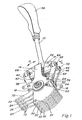
- the shifting gate shown in the figures contains one Shift lever 10, the one in the middle as a bridge 12th trained bracket is attached, as well as a console that essentially two laterally arranged, to each other spaced structure plates 14, 16, which by two rod-shaped spacers 18 serving as connecting elements, 20 are connected.
- Between the two Structure plates 14, 16 are four transmission levers 22, 24, 26, 28 and four spacer plates 30, 32, 34, 36 fixed to the housing arranged, which are alternatively layered.
- the spacer plates 30, 32, 34, 36 have aligned longitudinal bores 37 through which a bolt (not shown) can be inserted, around the spacer plates 30, 32, 34, 36 on a not shown Fasten housing.
- the structure plates 14, 16 and Transmission levers 22, 24, 26, 28 are on a housing-fixed Transverse axis 38 pivotally mounted.
- the transmission levers 22, 24, 26, 28 are all the same and each contain two legs.
- a first leg 58 extends starting from the transverse axis 38 in the direction of the shift lever 10.
- the first leg 58 of each transmission lever 22, 24, 26, 28 contains a contact piece 60 in its end region, too Called switching stone, the two opposite each other Has contact surfaces 62.
- Between every two neighboring ones Contact pieces 60 is a with a spacer plate 30, 32, 34, 36 connected fixed spacer 64.
- To the both ends of the bridge 12 are each in the transverse direction Q aligned pressure piece 66, 68 attached. The ends of the Pressure pieces 66, 68 are aligned with the contact surfaces 62.
- the instantaneous pole can be a contact piece 60 in this way Select that the ends of the two pressure pieces 66, 68 den Contact surfaces 62 of the selected contact piece 60 face.
- the shift lever 10 together with the Console pivoted in the transverse direction Q about the transverse axis 38, presses one of the pressure pieces 66, 68 against the corresponding one Contact surface 62 and pivots the associated Transmission element 22, 24, 26, 28.
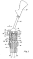
- the second legs 70 of the transmission levers 22, 24, 26, 28 are angled relative to the first legs 58 and stand laterally from the transverse axis 38 (Fig. 3).
- Each of these second Leg 70 contains three transverse bores 72.
- In these bores 72 can optionally be shown trains, for example, push-pull cables, which do not hang with a Switching device of a vehicle transmission shown in Connect. Since every second leg 70 firmly with one associated first leg 58 is connected, he follows it Movements. With a transverse deflection of the shift lever 10 the selected first leg 58 pivots and thus the Position of the associated second leg 70 shifted so that the push-pull cable suspended in the second leg 70 Leg movement on the switching device of the Vehicle transmission transmits to a gear or group appeal.
- Fig. 2 is attached to a structure plate 14
- Latching device 74 emerges. This contains a ball 76, the by an invisible spring against one on the bridge 12 attached locking profile 78 is pressed.
- the locking profile 78 defines locking positions of the shift lever 10, in which the Pressure pieces 66, 68 of a selected contact area 62 face.
- the shifting gate shown in FIG. 4 contains one in Longitudinal neutral alley N of the three Branch cross streets, the end points of each of a group A, B, C, D, E, F correspond to the vehicle transmission. Furthermore branches off of this in the end region of neutral alley N. hook-shaped cross alley from a parking position P of the vehicle transmission.
- the shift gate is in Shaft area of the shift lever 10 arranged and leaves only one Movement of the shift lever 10 within the neutral alley and Cross alleys too.
Landscapes
- Engineering & Computer Science (AREA)
- General Engineering & Computer Science (AREA)
- Mechanical Engineering (AREA)
- Arrangement Or Mounting Of Control Devices For Change-Speed Gearing (AREA)
- Control Of Transmission Device (AREA)
- Gear-Shifting Mechanisms (AREA)
Applications Claiming Priority (2)
| Application Number | Priority Date | Filing Date | Title |
|---|---|---|---|
| DE10060803A DE10060803A1 (de) | 2000-12-07 | 2000-12-07 | Schaltvorrichtung für ein Fahrzeuggetriebe |
| DE10060803 | 2000-12-07 |
Publications (3)
| Publication Number | Publication Date |
|---|---|
| EP1213509A2 true EP1213509A2 (fr) | 2002-06-12 |
| EP1213509A3 EP1213509A3 (fr) | 2006-01-11 |
| EP1213509B1 EP1213509B1 (fr) | 2008-07-16 |
Family
ID=7666127
Family Applications (1)
| Application Number | Title | Priority Date | Filing Date |
|---|---|---|---|
| EP01128586A Expired - Lifetime EP1213509B1 (fr) | 2000-12-07 | 2001-11-30 | Mécanisme de changement de vitesses pour transmission de véhicule |
Country Status (4)
| Country | Link |
|---|---|
| US (1) | US6647821B2 (fr) |
| EP (1) | EP1213509B1 (fr) |
| BR (1) | BR0105910B1 (fr) |
| DE (2) | DE10060803A1 (fr) |
Cited By (2)
| Publication number | Priority date | Publication date | Assignee | Title |
|---|---|---|---|---|
| EP1482214A3 (fr) * | 2003-05-26 | 2008-01-23 | Kojima Press Industry Co., Ltd. | Levier de changement de vitesse |
| DE102006039860B3 (de) * | 2006-08-25 | 2008-03-27 | Zf Friedrichshafen Ag | Betätigungsvorrichtung für Kraftfahrzeuggetriebe |
Families Citing this family (4)
| Publication number | Priority date | Publication date | Assignee | Title |
|---|---|---|---|---|
| DE10146783B4 (de) * | 2001-09-22 | 2008-12-18 | Adam Opel Ag | Lagerung eines Schalthebels |
| JP4781650B2 (ja) * | 2004-09-17 | 2011-09-28 | 川崎重工業株式会社 | 車両のシフトレバー装置 |
| US7458432B2 (en) * | 2006-06-16 | 2008-12-02 | Deere & Company | Dual lever steering control mechanism |
| US9593770B2 (en) * | 2015-04-15 | 2017-03-14 | Fca Us Llc | Automatic transmission shifter with speed sensitive damping |
Citations (1)
| Publication number | Priority date | Publication date | Assignee | Title |
|---|---|---|---|---|
| DE19922010A1 (de) | 1999-05-12 | 2000-11-23 | Deere & Co | Schaltvorrichtung für ein Fahrzeuggetriebe |
Family Cites Families (42)
| Publication number | Priority date | Publication date | Assignee | Title |
|---|---|---|---|---|
| US3057222A (en) * | 1961-12-13 | 1962-10-09 | Jr Edgar W Almquist | Shifting mechanism |
| NL289515A (fr) * | 1962-02-28 | |||
| US3082639A (en) * | 1962-09-11 | 1963-03-26 | Almquist Engineering Co | Gear shift |
| US3172301A (en) * | 1962-10-15 | 1965-03-09 | Jr George H Hurst | Gear shift |
| US3301084A (en) * | 1964-11-23 | 1967-01-31 | Kiekhaefer Corp | Single lever control system |
| US3329039A (en) * | 1965-05-10 | 1967-07-04 | Ford Motor Co | Manually controlled transmission gear shift assembly |
| NL6606473A (fr) * | 1965-05-14 | 1966-11-15 | ||
| US3323387A (en) * | 1965-05-25 | 1967-06-06 | Jr George H Hurst | Gear shift mechanism |
| US3633436A (en) * | 1970-10-09 | 1972-01-11 | Deere & Co | Single-lever actuated linkage for controlling the transmission and steering of a crawler tractor |
| US3636793A (en) * | 1970-11-18 | 1972-01-25 | Mr Gasket Co | Shifting apparatus |
| US3744336A (en) * | 1971-07-29 | 1973-07-10 | Fenton Co | Multiple speed gear shift |
| US3779096A (en) * | 1972-05-22 | 1973-12-18 | Hurst Performance | Shift control assembly |
| GB1402662A (en) * | 1973-01-18 | 1975-08-13 | Chrysler Uk | Gear change mechanisms |
| BR7603032A (pt) * | 1975-05-14 | 1977-05-31 | Massey Ferguson Services Nv | Aperfeicoamento em transmissao de mudanca de velocidade |
| JPS51141957A (en) * | 1975-05-30 | 1976-12-07 | Toyota Motor Corp | Operating device of change gear for automobile |
| US4028959A (en) * | 1976-06-25 | 1977-06-14 | Leonard Clarence Long | Straight action gear changing mechanism |
| US4132124A (en) * | 1976-09-29 | 1979-01-02 | Manno Kogyo Company, Limited | Shift mechanism for automotive transmission |
| JPS5632335Y2 (fr) * | 1976-10-30 | 1981-08-01 | ||
| US4129046A (en) * | 1977-03-21 | 1978-12-12 | Caterpillar Tractor Co. | Gear shift control |
| US4222284A (en) * | 1978-05-15 | 1980-09-16 | W. R. Grace & Co. | Selector pin assembly for manual transmission shifter |
| US4273004A (en) * | 1978-07-25 | 1981-06-16 | Morrison William M | Gear selector mechanism |
| JPS57190161A (en) * | 1981-05-19 | 1982-11-22 | Nissan Motor Co Ltd | Preventive mechanism of gear disengagement |
| DE73280T1 (de) * | 1981-08-26 | 1983-08-04 | Deere & Co., 61265 Moline, Ill. | Anordnung fuer die gangschaltung fuer ein fahrzeug. |
| US4513847A (en) * | 1982-09-30 | 1985-04-30 | Allis-Chalmers Corporation | Range shift and park lock control |
| US4515029A (en) * | 1982-11-08 | 1985-05-07 | Eaton Corporation | Compound variable mechanical advantage shifting mechanism |
| US4567785A (en) * | 1983-12-16 | 1986-02-04 | Eaton Corporation | Directly mounted master shift control |
| US4664221A (en) * | 1986-01-21 | 1987-05-12 | Deere & Company | Function control linkage for a vehicle |
| US4671131A (en) * | 1986-02-18 | 1987-06-09 | Cablecraft, Inc. | Transmitter for use with a two-cable shifting mechanism for a transmission |
| US4781074A (en) * | 1987-04-13 | 1988-11-01 | Long Leonard C | Shifter |
| FR2615798B1 (fr) * | 1987-05-25 | 1989-09-15 | Peugeot | Dispositif de commande d'une boite de vitesses de vehicule automobile |
| ES2007211A6 (es) * | 1987-05-27 | 1989-06-01 | Zahnradfabrik Friedrichshafen | Dispositivo de mando. |
| DE3831310A1 (de) * | 1988-09-15 | 1990-03-29 | Porsche Ag | Vorrichtung zum vorwaehlen und schalten eines kraftfahrzeug-gangschaltgetriebes |
| US4875383A (en) * | 1989-02-23 | 1989-10-24 | Dana Corporation | Dual ratio transmission shifter assembly with neutral safety switch |
| DE4002932A1 (de) * | 1990-02-01 | 1991-08-08 | Iveco Magirus | Vorrichtung zum schalten des getriebes eines kraftfahrzeuges |
| US5149023A (en) * | 1991-07-12 | 1992-09-22 | The Boeing Company | Mechanically-linked side stick controllers with isolated pitch and roll control movement |
| US5182961A (en) * | 1991-07-30 | 1993-02-02 | Honeywell Inc. | Three degree of freedom translational axis hand controller mechanism |
| DE4402443A1 (de) * | 1993-01-27 | 1994-07-28 | Mazda Motor | Schalteinrichtung für Handschaltgetriebe |
| DE4406598C2 (de) * | 1994-03-01 | 1996-10-31 | Daimler Benz Ag | Schalteinrichtung für ein selbsttätig schaltendes Wechselgetriebe mit einer mechanischen Sperre für den Rückwärtsgang in einem Kraftfahrzeug |
| DE19622514A1 (de) * | 1996-06-05 | 1997-12-18 | Deere & Co | Vorrichtung zur Neutralstellung eines Getriebes |
| DE19711237A1 (de) * | 1996-12-21 | 1998-07-02 | Deere & Co | Schalteinrichtung für ein Getriebe |
| DE19818864C1 (de) * | 1998-04-28 | 1999-11-04 | Daimler Chrysler Ag | Wähleinrichtung für ein automatisches Kraftfahrzeuggetriebe |
| DE19853934B4 (de) * | 1998-11-23 | 2006-05-04 | ZF Lemförder Metallwaren AG | Schaltvorrichtung eines Kraftfahrzeuggetriebes |
-
2000
- 2000-12-07 DE DE10060803A patent/DE10060803A1/de not_active Ceased
-
2001
- 2001-11-26 US US09/994,240 patent/US6647821B2/en not_active Expired - Lifetime
- 2001-11-30 DE DE50114119T patent/DE50114119D1/de not_active Expired - Lifetime
- 2001-11-30 EP EP01128586A patent/EP1213509B1/fr not_active Expired - Lifetime
- 2001-12-06 BR BRPI0105910-6A patent/BR0105910B1/pt not_active IP Right Cessation
Patent Citations (1)
| Publication number | Priority date | Publication date | Assignee | Title |
|---|---|---|---|---|
| DE19922010A1 (de) | 1999-05-12 | 2000-11-23 | Deere & Co | Schaltvorrichtung für ein Fahrzeuggetriebe |
Cited By (4)
| Publication number | Priority date | Publication date | Assignee | Title |
|---|---|---|---|---|
| EP1482214A3 (fr) * | 2003-05-26 | 2008-01-23 | Kojima Press Industry Co., Ltd. | Levier de changement de vitesse |
| US7363836B2 (en) | 2003-05-26 | 2008-04-29 | Kojima Press Industry Co., Ltd. | Shift lever apparatus |
| DE102006039860B3 (de) * | 2006-08-25 | 2008-03-27 | Zf Friedrichshafen Ag | Betätigungsvorrichtung für Kraftfahrzeuggetriebe |
| US8250943B2 (en) | 2006-08-25 | 2012-08-28 | Zf Friedrichshafen Ag | Actuating device for motor vehicle transmissions |
Also Published As
| Publication number | Publication date |
|---|---|
| EP1213509A3 (fr) | 2006-01-11 |
| US20020073796A1 (en) | 2002-06-20 |
| BR0105910A (pt) | 2002-08-06 |
| US6647821B2 (en) | 2003-11-18 |
| BR0105910B1 (pt) | 2010-01-26 |
| DE50114119D1 (de) | 2008-08-28 |
| DE10060803A1 (de) | 2002-07-04 |
| EP1213509B1 (fr) | 2008-07-16 |
Similar Documents
| Publication | Publication Date | Title |
|---|---|---|
| EP0828097B1 (fr) | Dispositif de commande d'une boíte de vitesses de véhicule automobile | |
| DE3641203C2 (fr) | ||
| DE3824296C2 (fr) | ||
| EP0052794B1 (fr) | Dispositif de commande pour la transmission d'un véhicule utilitaire | |
| DE69905724T2 (de) | Steuereinrichtung | |
| DE19632859A1 (de) | Betätigungseinrichtung für ein Kraftfahrzeuggetriebe | |
| EP0699853B1 (fr) | Tringlerie de sélection des vitesses pour boîte de vitesse d'un véhicule | |
| DE4308637A1 (de) | Schaltvorrichtung für ein Handschaltgetriebe eines Kraftfahrzeuges | |
| EP0933563A1 (fr) | Dispositif de changement de vitesses pour transmission de vitesse de véhicule | |
| DE102008017862B4 (de) | Bedieneinrichtung für ein Handschaltgetriebe | |
| EP1213509B1 (fr) | Mécanisme de changement de vitesses pour transmission de véhicule | |
| DE3839319C2 (fr) | ||
| DE69602687T2 (de) | Steuerhebelanordnung mit verbesserter Positionsarretierung | |
| EP1531290A2 (fr) | Dispositif de sélection de vitesse | |
| EP2751448A1 (fr) | Dispositif de changement de vitesse | |
| EP1267240A1 (fr) | Changement de vitesse pour une boíte de vitesses manuelle d'un véhicule automobile | |
| EP1499936A1 (fr) | Dispositif de commutation a plusieurs voies | |
| EP0782510B1 (fr) | Commutateur monte sur la colonne de direction, servant d'organe de changement de vitesses avec possibilite de fixation en position neutre | |
| DE3932543C2 (de) | Ventilbetätigungseinrichtung | |
| DE19526995B4 (de) | Seilzugbetätigender Kraftfahrzeugschalthebel-Gelenkmechanismus | |
| DE4428205A1 (de) | Betätigungseinrichtung zum Steuern des Gangwechsels eines Getriebes für ein Kraftfahrzeug | |
| DE3002968C2 (de) | Betätigungsvorrichtung für Geschwindigkeitswechselgetriebe von Kraftfahrzeugen | |
| DE19614723C2 (de) | Vorrichtung zum Ansteuern einer Lenkung von Fahrzeugen | |
| DE19803608A1 (de) | Schaltvorrichtung für ein Zahnräderwechselgetriebe | |
| DE69402162T2 (de) | Vorrichtung zur Steuerung eines Kraftfahrzeuggetriebes |
Legal Events
| Date | Code | Title | Description |
|---|---|---|---|
| PUAI | Public reference made under article 153(3) epc to a published international application that has entered the european phase |
Free format text: ORIGINAL CODE: 0009012 |
|
| AK | Designated contracting states |
Kind code of ref document: A2 Designated state(s): AT BE CH CY DE DK ES FI FR GB GR IE IT LI LU MC NL PT SE TR |
|
| AX | Request for extension of the european patent |
Free format text: AL;LT;LV;MK;RO;SI |
|
| PUAL | Search report despatched |
Free format text: ORIGINAL CODE: 0009013 |
|
| AK | Designated contracting states |
Kind code of ref document: A3 Designated state(s): AT BE CH CY DE DK ES FI FR GB GR IE IT LI LU MC NL PT SE TR |
|
| AX | Request for extension of the european patent |
Extension state: AL LT LV MK RO SI |
|
| 17P | Request for examination filed |
Effective date: 20060711 |
|
| AKX | Designation fees paid |
Designated state(s): DE FR GB IT |
|
| 17Q | First examination report despatched |
Effective date: 20060911 |
|
| GRAP | Despatch of communication of intention to grant a patent |
Free format text: ORIGINAL CODE: EPIDOSNIGR1 |
|
| GRAS | Grant fee paid |
Free format text: ORIGINAL CODE: EPIDOSNIGR3 |
|
| GRAA | (expected) grant |
Free format text: ORIGINAL CODE: 0009210 |
|
| AK | Designated contracting states |
Kind code of ref document: B1 Designated state(s): DE FR GB IT |
|
| REG | Reference to a national code |
Ref country code: GB Ref legal event code: FG4D Free format text: NOT ENGLISH |
|
| REF | Corresponds to: |
Ref document number: 50114119 Country of ref document: DE Date of ref document: 20080828 Kind code of ref document: P |
|
| PLBE | No opposition filed within time limit |
Free format text: ORIGINAL CODE: 0009261 |
|
| STAA | Information on the status of an ep patent application or granted ep patent |
Free format text: STATUS: NO OPPOSITION FILED WITHIN TIME LIMIT |
|
| 26N | No opposition filed |
Effective date: 20090417 |
|
| REG | Reference to a national code |
Ref country code: FR Ref legal event code: PLFP Year of fee payment: 15 |
|
| REG | Reference to a national code |
Ref country code: FR Ref legal event code: PLFP Year of fee payment: 16 |
|
| REG | Reference to a national code |
Ref country code: FR Ref legal event code: PLFP Year of fee payment: 17 |
|
| PGFP | Annual fee paid to national office [announced via postgrant information from national office to epo] |
Ref country code: DE Payment date: 20201021 Year of fee payment: 20 Ref country code: GB Payment date: 20201127 Year of fee payment: 20 Ref country code: FR Payment date: 20201125 Year of fee payment: 20 Ref country code: IT Payment date: 20201123 Year of fee payment: 20 |
|
| REG | Reference to a national code |
Ref country code: DE Ref legal event code: R071 Ref document number: 50114119 Country of ref document: DE |
|
| REG | Reference to a national code |
Ref country code: GB Ref legal event code: PE20 Expiry date: 20211129 |
|
| PG25 | Lapsed in a contracting state [announced via postgrant information from national office to epo] |
Ref country code: GB Free format text: LAPSE BECAUSE OF EXPIRATION OF PROTECTION Effective date: 20211129 |