EP1213547A2 - Réchauffeur indépendant pour moteur de voiture - Google Patents
Réchauffeur indépendant pour moteur de voiture Download PDFInfo
- Publication number
- EP1213547A2 EP1213547A2 EP01125229A EP01125229A EP1213547A2 EP 1213547 A2 EP1213547 A2 EP 1213547A2 EP 01125229 A EP01125229 A EP 01125229A EP 01125229 A EP01125229 A EP 01125229A EP 1213547 A2 EP1213547 A2 EP 1213547A2
- Authority
- EP
- European Patent Office
- Prior art keywords
- housing part
- housing
- heater
- axis
- rotation
- Prior art date
- Legal status (The legal status is an assumption and is not a legal conclusion. Google has not performed a legal analysis and makes no representation as to the accuracy of the status listed.)
- Granted
Links
Images
Classifications
-
- B—PERFORMING OPERATIONS; TRANSPORTING
- B60—VEHICLES IN GENERAL
- B60H—ARRANGEMENTS OF HEATING, COOLING, VENTILATING OR OTHER AIR-TREATING DEVICES SPECIALLY ADAPTED FOR PASSENGER OR GOODS SPACES OF VEHICLES
- B60H1/00—Heating, cooling or ventilating devices
- B60H1/22—Heating, cooling or ventilating devices the heat source being other than the propulsion plant
- B60H1/2203—Heating, cooling or ventilating devices the heat source being other than the propulsion plant the heat being derived from burners
- B60H1/2209—Heating, cooling or ventilating devices the heat source being other than the propulsion plant the heat being derived from burners arrangements of burners for heating an intermediate liquid
-
- F—MECHANICAL ENGINEERING; LIGHTING; HEATING; WEAPONS; BLASTING
- F24—HEATING; RANGES; VENTILATING
- F24H—FLUID HEATERS, e.g. WATER OR AIR HEATERS, HAVING HEAT-GENERATING MEANS, e.g. HEAT PUMPS, IN GENERAL
- F24H9/00—Details
- F24H9/02—Casings; Cover lids; Ornamental panels
-
- B—PERFORMING OPERATIONS; TRANSPORTING
- B60—VEHICLES IN GENERAL
- B60H—ARRANGEMENTS OF HEATING, COOLING, VENTILATING OR OTHER AIR-TREATING DEVICES SPECIALLY ADAPTED FOR PASSENGER OR GOODS SPACES OF VEHICLES
- B60H1/00—Heating, cooling or ventilating devices
- B60H1/22—Heating, cooling or ventilating devices the heat source being other than the propulsion plant
- B60H2001/2268—Constructional features
- B60H2001/2278—Connectors, water supply, housing, mounting brackets
Definitions
- the invention relates to a motor-independently operable Heater of a motor vehicle, in particular in the form of a Auxiliary heater or an auxiliary heater, with the characteristics of Preamble of claim 1.
- Such a heater is for example from the WO 00/24600 known and has a housing in which a Burner and a heat exchanger coaxially enveloping the burner are accommodated.
- the housing is also with connection piece for the water or air flow and for the Water or air return equipped.
- the present invention addresses the problem an embodiment for a heater of the type mentioned to be specified in different installation space situations is relatively easy to assemble and a relatively simple one Cable routing enables.
- the invention is based on the general idea of the heater to divide into two device units that are assigned in Housing parts are housed, these housing parts assembled in different relative positions to each other to be able to reassemble for that Heater form a common housing.
- connection means with which the housing parts at least in two different, to each other around an axis of rotation rotated relative positions can be attached to each other are.
- the burner is on one housing part attached and arranged coaxially to the axis of rotation, while the heat exchanger is attached to the other housing part and is arranged coaxially to the axis of rotation. Because Brenner and Heat exchangers are generally rotationally symmetrical are the functional unit of burner and heat exchanger in any rotated relative position between the burner and the heat exchanger.
- the measure according to the invention enables connections or Connection groups on one and / or on the other Housing part are arranged by setting a suitable Relative position between the two housing parts depending on the existing installation conditions be positioned in a variety of ways. This can the heater according to the invention individually to each prevailing installation situation can be adjusted, which assembly and routing from and to the heater improved.
- the first housing part can have connecting pieces for fuel and / or fresh gas and / or exhaust gas.
- By a corresponding rotation adjustment of the first housing part can therefore be different for these connecting pieces Positions can be set.
- the second housing part can have connecting pieces for a flow and for a return of a heat transfer medium with which the heat exchanger is acted upon. By turning the second housing part can thus in this connector be positioned in different ways.
- a pumping device for the heat transfer medium be arranged on or in the second housing part next to the Heat exchanger.
- This also makes it a modular one Structure for this device unit achieved because the functional pump device interacting with the heat exchanger is arranged in or on the same housing part.
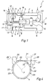
- connection means 5 are provided, which here with each housing part 3, 4 in the form of an internal, circumferential flange are formed. Screw connections 6, which are indicated by dash-dotted lines can for example by a cover, not shown here of the housing 2 are performed.
- the connection means 5 are designed so that the two housing parts 3 and 4 at least in two different relative positions are attachable, these relative positions by a rotation of the two housing parts 3, 4 relative to one another result about an axis of rotation 7. They are preferably at one another to be connected sides of the housing parts 3.4 so designed that when assembled housing 2 a closed outer contour results.
- This means in particular that the cross sections of the two housing parts 3, 4 at least in an area 8 in which the connection means 5 are arranged are, in all intended relative positions essentially lie congruently on top of each other.
- the first housing part 3 contains a burner 9 on the first Fixed housing part 3 and arranged coaxially to the axis of rotation 7 is.
- the burner 9 stands in the axial direction of the first housing part 3 and protrudes when assembled Housing 2 in a heat exchanger or heat exchanger 10 one, which is housed in the second housing part 4.
- the Heat exchanger 10 is attached to the second housing part 4 and also aligned coaxially to the axis of rotation 7.
- the first housing part 3 contains the one shown here special embodiment also a blower 11, the Burner 9 supplies fresh gas and thereby at the same time from Burner 9 discharges exhaust gas generated from burner 9.
- the first housing part 3 has a supply of fresh gas Fresh gas connecting piece 12; for the removal of exhaust gas a corresponding exhaust connection piece 13 is provided.
- the Coupling between burner 9 and heat exchanger 10 takes place with the housing 2 assembled so that the ones produced by the burner 9 exhaust gases are called the heat exchanger in the usual way 10 can act, the cooled exhaust gases from an exhaust line 14 can be detected in the first housing part 3 is housed.
- the corresponding connections and Connections are preferably designed so that they are in each of the adjustable relative positions between the housing parts 3 and 4 are sufficiently gas-tight.
- the first housing part 3 also contains a fuel metering device 15, which have a fuel connector 16 to a fuel supply of a motor vehicle is connected, in which the heater 1 is installed is.
- the fuel metering device 15 supplies the Burner 9 with the required amount of fuel.
- a control unit 17 housed the burner via appropriate lines 9 or a glow plug, not shown, the fuel metering device 15 and the blower 11 actuated.
- the control unit 17 via a corresponding interface 18 also operates a pump 19 in the second housing part 4 is housed and to act on the heat exchanger 10 serves with a heat transfer medium.
- This Pump 19 is on the suction side with a return connection piece 20 and pressure side with an input of Heat exchanger 10 connected. An output of the heat exchanger 10 is connected to a flow connector 21. Via the return connection piece arranged on the second housing part 4 20 and flow connector 21 is the Heat exchanger 10 integrated in a fluid circuit of the vehicle, such that the heater 1 can be operated independently of the engine and serves as an auxiliary heater or as an auxiliary heater. at pure heating can also be dispensed with the pump 19.
- the Pump 19 can also be modular on the outside of housing 2 be mounted.
- the coolant of an engine cooling circuit so that the heater 1 is a water heater forms.
- the one charged with the coolant or "cooling water” Heat exchanger 10 envelops the burner 9 and forms thereby a so-called “water jacket”.
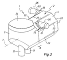
- the housing parts 3, 4 have at least in area 8 of the adjoining pages a regular octagonal outer cross-section. While in the case of the first housing part 3, the octagonal outer cross section is only formed in the area of the connection means 5, has the second housing part 4 along its entire length axial extension the octagonal outer cross section. Accordingly has the outer contour of the second housing part 4 eight flat outer surfaces 22, with adjacent outer surfaces 22 each inclined at 45 ° to each other. Between two adjacent outer surfaces 22 are virtually in the Edges of the outer cross section grooves 23 formed here have no undercut. Embodiments are likewise possible in which the grooves 23 have an undercut. The grooves 23 serve as points of attack for fasteners, with which the heater 1 can be attached to the vehicle is.
- the second housing part 2 has the first housing part 3 on one side, in Fig. 2 above, a lid 24. On one the side opposite the cover 24, in FIG. 2 below, the first housing part 3 has the fresh gas connecting piece 12 and the exhaust port 13. The associated one Fuel connector 16 is not visible here.
- the second housing part 2 has two different outer surfaces 22 on the one hand the return connection piece 20 and other the flow connector 21.
- the connecting pieces 20, 21 of the second housing part 4 are here in each case by means of a holding device 25 on the second housing part 2 fixed, which allows an adjustment of the connecting piece 20,21. 2 and 3 is an embodiment shown, in which the connecting piece 20.21 in 90 ° steps each with respect to an associated pivot axis 26 are removable. This pivot axis 26 is perpendicular on the axis of rotation 7.
- FIG. 2 is between the housing parts 3 and 4 set a first relative position at which the cover 24 above and the connecting piece 12 and 13th of the first housing part 3 are arranged below.
- the connecting pieces 20, 21 of the second housing part 4 are shown in FIG. 2 oriented so that they are parallel to each other and perpendicular run to the axis of rotation 7.
- the return connector 20 directed backwards, while the flow connector 21 is directed forward.
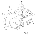
- FIG. 3 shows a second one Relative position between the two housing parts 3 and 4, in which the two housing parts 3 and 4 about the axis of rotation 7 are rotated 90 ° against each other. Accordingly, here the lid 24 arranged at the rear while the connecting piece 12 and 13 of the first housing part 3 are in the front.
- the connecting pieces 20 and 21 of the second housing part 4 repositioned such that both after point upwards or protrude upwards. Thereby extend the two connecting pieces 20, 21 again perpendicular to the axis of rotation 7 and parallel to each other. The connecting piece 20 and 21 are therefore repositioned by 180 ° in FIG. 3 compared to FIG. 2.
- FIG. 4 are the connecting piece 20,21 of the second Housing part 4 preferably angled at about 45 ° and dimensioned so that the respective connecting piece 20.21 in two pivoted by 180 ° with respect to the associated pivot axis 26 Positions is always arranged so that one of second housing part 4 facing away section of the outer contour of the respective connection piece 20, 21 in a level 27 lies or extends in a plane 27 in which one of the Outer surfaces 22 is located adjacent to that outer surface 22 is at which the respective connection piece 20,21 is arranged.
- Fig. 4 are for the flow connector 21 reproduced these two positions, one with solid lines and the other with broken lines is shown.
Landscapes
- Engineering & Computer Science (AREA)
- Physics & Mathematics (AREA)
- Thermal Sciences (AREA)
- Mechanical Engineering (AREA)
- Chemical & Material Sciences (AREA)
- Combustion & Propulsion (AREA)
- General Engineering & Computer Science (AREA)
- Air-Conditioning For Vehicles (AREA)
Applications Claiming Priority (2)
| Application Number | Priority Date | Filing Date | Title |
|---|---|---|---|
| DE10060705 | 2000-12-07 | ||
| DE2000160705 DE10060705B4 (de) | 2000-12-07 | 2000-12-07 | Motorunabhängiges Heizgerät eines Kraftfahrzeuges |
Publications (3)
| Publication Number | Publication Date |
|---|---|
| EP1213547A2 true EP1213547A2 (fr) | 2002-06-12 |
| EP1213547A3 EP1213547A3 (fr) | 2003-12-03 |
| EP1213547B1 EP1213547B1 (fr) | 2005-12-28 |
Family
ID=7666053
Family Applications (1)
| Application Number | Title | Priority Date | Filing Date |
|---|---|---|---|
| EP20010125229 Expired - Lifetime EP1213547B1 (fr) | 2000-12-07 | 2001-10-24 | Radiateur indépendant pour moteur de voiture |
Country Status (4)
| Country | Link |
|---|---|
| EP (1) | EP1213547B1 (fr) |
| JP (1) | JP2002205533A (fr) |
| CZ (1) | CZ20014353A3 (fr) |
| DE (2) | DE10060705B4 (fr) |
Cited By (4)
| Publication number | Priority date | Publication date | Assignee | Title |
|---|---|---|---|---|
| EP1273852A2 (fr) | 2001-07-06 | 2003-01-08 | BSH Bosch und Siemens Hausgeräte GmbH | Procédé de fonctionnement d'un appareil de cuisson et appareil de cuisson |
| DE102007011814A1 (de) * | 2007-03-12 | 2008-09-18 | J. Eberspächer GmbH & Co. KG | Einrichtung zum Konditionieren von in einen Fahrzeuginnenraum einzuleitender Luft |
| EP3424761A1 (fr) * | 2017-07-03 | 2019-01-09 | Eberspächer Climate Control Systems GmbH & Co. KG. | Système support |
| EP4336118A1 (fr) * | 2022-09-06 | 2024-03-13 | Kyungdong Navien Co., Ltd. | Appareil de chauffage d'eau |
Families Citing this family (4)
| Publication number | Priority date | Publication date | Assignee | Title |
|---|---|---|---|---|
| DE10108833B4 (de) * | 2001-02-23 | 2008-08-28 | Volkswagen Ag | Heizgerät, insbesondere für ein Kraftfahrzeug |
| DE102006048440A1 (de) * | 2006-10-12 | 2008-04-17 | Webasto Ag | System mit einem modular ausgebildeten Heizgerät und Verfahren zum Wechseln eines Moduls des Heizgeräts |
| DE102011088568B4 (de) * | 2011-12-14 | 2021-02-18 | Eberspächer Climate Control Systems GmbH | Fahrzeugheizgerät |
| DE102015103421B3 (de) * | 2015-03-09 | 2016-05-12 | Eberspächer Climate Control Systems GmbH & Co. KG | Gebläse, insbesondere Verbrennungsluftgebläse für ein Fahrzeugheizgerät |
Citations (1)
| Publication number | Priority date | Publication date | Assignee | Title |
|---|---|---|---|---|
| WO2000024600A1 (fr) | 1998-10-24 | 2000-05-04 | J. Eberspächer Gmbh & Co. | Appareil de chauffage d'un vehicule, en particulier appareil de chauffage a eau sous forme d'un chauffage d'appoint ou d'un chauffage auxiliaire |
Family Cites Families (3)
| Publication number | Priority date | Publication date | Assignee | Title |
|---|---|---|---|---|
| DE2048760B2 (de) * | 1970-10-03 | 1976-06-24 | Webasto-Werk W. Baier Kg, 8031 Stockdorf | Heizvorrichtung fuer fahrzeuge |
| DE19502082C2 (de) * | 1995-01-24 | 1999-08-19 | Eberspaecher J Gmbh & Co | Fahrzeugheizgerät |
| DE10006396A1 (de) * | 1999-05-06 | 2000-11-09 | Eberspaecher J Gmbh & Co | Heizsystem, insbesondere für Kraftfahrzeuge |
-
2000
- 2000-12-07 DE DE2000160705 patent/DE10060705B4/de not_active Expired - Fee Related
-
2001
- 2001-10-24 EP EP20010125229 patent/EP1213547B1/fr not_active Expired - Lifetime
- 2001-10-24 DE DE50108534T patent/DE50108534D1/de not_active Expired - Lifetime
- 2001-12-04 CZ CZ20014353A patent/CZ20014353A3/cs unknown
- 2001-12-06 JP JP2001373218A patent/JP2002205533A/ja active Pending
Patent Citations (1)
| Publication number | Priority date | Publication date | Assignee | Title |
|---|---|---|---|---|
| WO2000024600A1 (fr) | 1998-10-24 | 2000-05-04 | J. Eberspächer Gmbh & Co. | Appareil de chauffage d'un vehicule, en particulier appareil de chauffage a eau sous forme d'un chauffage d'appoint ou d'un chauffage auxiliaire |
Cited By (8)
| Publication number | Priority date | Publication date | Assignee | Title |
|---|---|---|---|---|
| EP1273852A2 (fr) | 2001-07-06 | 2003-01-08 | BSH Bosch und Siemens Hausgeräte GmbH | Procédé de fonctionnement d'un appareil de cuisson et appareil de cuisson |
| DE102007011814A1 (de) * | 2007-03-12 | 2008-09-18 | J. Eberspächer GmbH & Co. KG | Einrichtung zum Konditionieren von in einen Fahrzeuginnenraum einzuleitender Luft |
| EP3424761A1 (fr) * | 2017-07-03 | 2019-01-09 | Eberspächer Climate Control Systems GmbH & Co. KG. | Système support |
| CN109203915A (zh) * | 2017-07-03 | 2019-01-15 | 埃贝斯佩歇气候控制系统有限责任两合公司 | 支架单元 |
| RU2682957C1 (ru) * | 2017-07-03 | 2019-03-22 | Эбершпехер Клаймит Контрол Системз Гмбх Унд Ко. Кг | Несущая конструкция |
| US11305613B2 (en) | 2017-07-03 | 2022-04-19 | Eberspächer Climate Control Systems GmbH | Carrier device |
| CN109203915B (zh) * | 2017-07-03 | 2022-04-19 | 埃贝斯佩歇气候控制系统有限公司 | 支架单元 |
| EP4336118A1 (fr) * | 2022-09-06 | 2024-03-13 | Kyungdong Navien Co., Ltd. | Appareil de chauffage d'eau |
Also Published As
| Publication number | Publication date |
|---|---|
| EP1213547A3 (fr) | 2003-12-03 |
| DE50108534D1 (de) | 2006-02-02 |
| DE10060705A1 (de) | 2002-06-20 |
| DE10060705B4 (de) | 2008-04-17 |
| CZ20014353A3 (cs) | 2002-07-17 |
| EP1213547B1 (fr) | 2005-12-28 |
| JP2002205533A (ja) | 2002-07-23 |
Similar Documents
| Publication | Publication Date | Title |
|---|---|---|
| DE102005031300B4 (de) | Brennkraftmaschine mit Kühlsystem und Abgasrückführsystem | |
| DE3917108C1 (fr) | ||
| DE602004004016T2 (de) | Verfahren zur Ventilsteuerung eines Abgassystems | |
| DE69919583T2 (de) | Vorrichtung für eine brennkraftmaschine mit aufladung | |
| EP2018472B1 (fr) | Ensemble de soupapes pour système de recyclage des gaz d'échappement | |
| DE69815882T2 (de) | Anlage einer brennkraftmaschine | |
| EP0940566A2 (fr) | Dispositif de commande pour le circuit de refroidissement et de chauffage d'un moteur à combustion interne | |
| DE102007024631A1 (de) | Integriertes Auflademodul | |
| EP0663309B1 (fr) | Dispositif de chauffage ou de climatisation, en particulier pour l'installation dans un véhicule automobile | |
| DE3135909A1 (de) | Vorrichtung zum beheizen und belueften von fahrzeugraeumen o.dgl. | |
| EP1213547B1 (fr) | Radiateur indépendant pour moteur de voiture | |
| DE10216773B4 (de) | Kühler für ein dem Hauptabgasstrom eines Verbrennungsmotors entnommenes Abgas | |
| DE2437232B2 (de) | Heizungs- bzw. klimaanlage fuer kraftfahrzeuge | |
| DE19744596A1 (de) | Abgasrückführventil | |
| DE10107909C5 (de) | Modulsystem für ein Heizgerät | |
| DE9002588U1 (de) | Heizgerät für mobile Einheiten, insbesondere Zusatzheizung für Kraftfahrzeuge | |
| EP0753657B1 (fr) | Collecteur d'admission d'air pour un moteur à combustion interne | |
| EP2072776A2 (fr) | Agencement de transmission de chaleur pour un véhicule | |
| DE102006037761A1 (de) | Befestigungsanordnung für einen Ladeluftkühler und einen Wasserkühler | |
| EP4127483B1 (fr) | Ventilateur à jet pour la ventilation de tunnels, système de ventilateur à jet et procédé | |
| EP1062411A1 (fr) | Conduite pour gaz d'echappement refroidie par eau | |
| EP1455079B1 (fr) | Dispositif de transfert de chaleur entre le gaz d'échappement et un fluide de refroidissement | |
| DE102008013675B4 (de) | Innere Gestaltung des Gehäuses einer Kühlmittelpumpe mit mehreren Auslasskanälen | |
| EP1727976B1 (fr) | Moteur a combustion interne a dispositif d'humidification et echangeur thermique | |
| DE102004048867A1 (de) | Wassergekühlte Brennkraftmaschine mit V-förmig angeordneten Zylinderreihen |
Legal Events
| Date | Code | Title | Description |
|---|---|---|---|
| PUAI | Public reference made under article 153(3) epc to a published international application that has entered the european phase |
Free format text: ORIGINAL CODE: 0009012 |
|
| AK | Designated contracting states |
Kind code of ref document: A2 Designated state(s): AT BE CH CY DE DK ES FI FR GB GR IE IT LI LU MC NL PT SE TR |
|
| AX | Request for extension of the european patent |
Free format text: AL;LT;LV;MK;RO;SI |
|
| PUAL | Search report despatched |
Free format text: ORIGINAL CODE: 0009013 |
|
| AK | Designated contracting states |
Kind code of ref document: A3 Designated state(s): AT BE CH CY DE DK ES FI FR GB GR IE IT LI LU MC NL PT SE TR |
|
| AX | Request for extension of the european patent |
Extension state: AL LT LV MK RO SI |
|
| 17P | Request for examination filed |
Effective date: 20040603 |
|
| AKX | Designation fees paid |
Designated state(s): DE FR GB SE |
|
| GRAP | Despatch of communication of intention to grant a patent |
Free format text: ORIGINAL CODE: EPIDOSNIGR1 |
|
| GRAS | Grant fee paid |
Free format text: ORIGINAL CODE: EPIDOSNIGR3 |
|
| GRAA | (expected) grant |
Free format text: ORIGINAL CODE: 0009210 |
|
| AK | Designated contracting states |
Kind code of ref document: B1 Designated state(s): DE FR GB SE |
|
| REG | Reference to a national code |
Ref country code: GB Ref legal event code: FG4D Free format text: NOT ENGLISH |
|
| REF | Corresponds to: |
Ref document number: 50108534 Country of ref document: DE Date of ref document: 20060202 Kind code of ref document: P |
|
| GBT | Gb: translation of ep patent filed (gb section 77(6)(a)/1977) |
Effective date: 20060227 |
|
| REG | Reference to a national code |
Ref country code: SE Ref legal event code: TRGR |
|
| ET | Fr: translation filed | ||
| PLBE | No opposition filed within time limit |
Free format text: ORIGINAL CODE: 0009261 |
|
| STAA | Information on the status of an ep patent application or granted ep patent |
Free format text: STATUS: NO OPPOSITION FILED WITHIN TIME LIMIT |
|
| 26N | No opposition filed |
Effective date: 20060929 |
|
| PGFP | Annual fee paid to national office [announced via postgrant information from national office to epo] |
Ref country code: SE Payment date: 20081027 Year of fee payment: 8 |
|
| PGFP | Annual fee paid to national office [announced via postgrant information from national office to epo] |
Ref country code: FR Payment date: 20081021 Year of fee payment: 8 |
|
| PGFP | Annual fee paid to national office [announced via postgrant information from national office to epo] |
Ref country code: GB Payment date: 20081024 Year of fee payment: 8 |
|
| EUG | Se: european patent has lapsed | ||
| REG | Reference to a national code |
Ref country code: FR Ref legal event code: ST Effective date: 20100630 |
|
| PG25 | Lapsed in a contracting state [announced via postgrant information from national office to epo] |
Ref country code: FR Free format text: LAPSE BECAUSE OF NON-PAYMENT OF DUE FEES Effective date: 20091102 |
|
| PG25 | Lapsed in a contracting state [announced via postgrant information from national office to epo] |
Ref country code: GB Free format text: LAPSE BECAUSE OF NON-PAYMENT OF DUE FEES Effective date: 20091024 |
|
| PG25 | Lapsed in a contracting state [announced via postgrant information from national office to epo] |
Ref country code: SE Free format text: LAPSE BECAUSE OF NON-PAYMENT OF DUE FEES Effective date: 20091025 |
|
| PGFP | Annual fee paid to national office [announced via postgrant information from national office to epo] |
Ref country code: DE Payment date: 20131031 Year of fee payment: 13 |
|
| REG | Reference to a national code |
Ref country code: DE Ref legal event code: R119 Ref document number: 50108534 Country of ref document: DE |
|
| PG25 | Lapsed in a contracting state [announced via postgrant information from national office to epo] |
Ref country code: DE Free format text: LAPSE BECAUSE OF NON-PAYMENT OF DUE FEES Effective date: 20150501 |