EP1213557A2 - Rohranordnung, Fliesskanalstruktur und ein Wärmetauscher - Google Patents
Rohranordnung, Fliesskanalstruktur und ein Wärmetauscher Download PDFInfo
- Publication number
- EP1213557A2 EP1213557A2 EP01660221A EP01660221A EP1213557A2 EP 1213557 A2 EP1213557 A2 EP 1213557A2 EP 01660221 A EP01660221 A EP 01660221A EP 01660221 A EP01660221 A EP 01660221A EP 1213557 A2 EP1213557 A2 EP 1213557A2
- Authority
- EP
- European Patent Office
- Prior art keywords
- tube structure
- flow channel
- tube
- heat exchanger
- wall
- Prior art date
- Legal status (The legal status is an assumption and is not a legal conclusion. Google has not performed a legal analysis and makes no representation as to the accuracy of the status listed.)
- Granted
Links
Images


Classifications
-
- F—MECHANICAL ENGINEERING; LIGHTING; HEATING; WEAPONS; BLASTING
- F28—HEAT EXCHANGE IN GENERAL
- F28F—DETAILS OF HEAT-EXCHANGE AND HEAT-TRANSFER APPARATUS, OF GENERAL APPLICATION
- F28F9/00—Casings; Header boxes; Auxiliary supports for elements; Auxiliary members within casings
- F28F9/02—Header boxes; End plates
- F28F9/04—Arrangements for sealing elements into header boxes or end plates
- F28F9/06—Arrangements for sealing elements into header boxes or end plates by dismountable joints
- F28F9/10—Arrangements for sealing elements into header boxes or end plates by dismountable joints by screw-type connections, e.g. gland
-
- F—MECHANICAL ENGINEERING; LIGHTING; HEATING; WEAPONS; BLASTING
- F28—HEAT EXCHANGE IN GENERAL
- F28F—DETAILS OF HEAT-EXCHANGE AND HEAT-TRANSFER APPARATUS, OF GENERAL APPLICATION
- F28F9/00—Casings; Header boxes; Auxiliary supports for elements; Auxiliary members within casings
- F28F9/02—Header boxes; End plates
- F28F9/04—Arrangements for sealing elements into header boxes or end plates
- F28F9/06—Arrangements for sealing elements into header boxes or end plates by dismountable joints
- F28F9/12—Arrangements for sealing elements into header boxes or end plates by dismountable joints by flange-type connections
Definitions
- the invention relates to a tube structure for heat exchangers, wherein the tube structure is intended to be fixed between opposite walls of a flow channel, or the like, for a first heat transfer medium of a heat exchanger, and wherein a second heat transfer medium is arranged to flow through the tube structure.
- the invention also relates to a flow channel structure which is arranged to be used as a part of a heat exchanger, wherein a first heat transfer medium flows in the flow channel, and wherein the flow channel structure, provided by means of a wall structure and having a closed cross-section, has a first wall and a second wall, one or more tube structures being placed in the flow channel between the walls, a second heat transfer medium flowing through the tube structures.
- the invention also relates to a heat exchanger comprising a combination of a flow channel structure and a tube structure placed therein, wherein the tube structure is fixed between opposite walls of the flow channel or the like of the heat exchanger, and wherein a first heat transfer medium flows in the flow channel and a second heat transfer medium flows through the tube structure.
- the invention also relates to the use of a tube structure, a flow channel structure and a heat exchanger as a pre-heater for air in a boiler plant.
- the tube structure, flow channel structure and heat exchanger according to the invention are intended to be used particularly, but not solely, when heat is to be transferred from flue gases of the boiler plant to the combustion air to be introduced into the furnace of the boiler plant.
- the structure is a pre-heater for air, a so-called Luvo heat exchanger structure.
- these heat exchanger structures comprise horizontal tubes which are connected in a gas-tight manner to vertical tube plates which normally also constitute two of the walls of the flue gas channel forming the flow channel.
- the combustion air flows inside the tubes, and the flue gases discharged from the furnace of the boiler plant flow outside the tubes, transversely with respect to the tubes. Naturally, the flow can also be arranged vice versa according to the practical application.
- the Luvo heat exchanger is formed of one or more tube banks which are assembled in such a way that a group of single tubes are connected at opposite ends to two wall plates which partly form the wall structure of the flow channel and are provided with openings at the locations of the tubes, to form a tube bank by welding either directly or by means of an intermediate sleeve connected to the tube.
- the problem lies particularly in that strong corrosion is present in the tubes of the tube banks placed in the coldest part of the flue gas channel, when the temperature of the flue gases is close to or within the range of the acid dew point.
- Manufacturing by welding limits the number of available materials, because the tubes and the wall plates which form at least part of the wall structure of the flue gas channel must be weldable to each other. Also, it is not possible to use coatings on the outer surface of the tubes, because coatings do not stand the heat developed by welding without being damaged, and the coating of the welded location cannot be repaired afterwards.
- the tube bank assembled by welding has such a structure that the ready welded tube bank cannot be coated afterwards.
- the tube structure according to the invention is primarily characterized in that the tube structure comprises, at its both ends, fixing means for fixing the tube structure to the walls of the flow channel in a releasable manner.
- the flow channel structure according to the invention is primarily characterized in that the first and second walls of the flow channel structure are provided with at least one compatible pair of holes for the insertion of at least one tube structure through the second hole of the pair of holes to the flow channel structure in a sealed and releasable manner.
- the heat exchanger according to the invention is primarily characterized in that the tube structure comprises, at its both ends, fixing means for fixing the tube structure in a releasable manner to the walls of the flow channel, and that the first and second walls of the flow channel structure comprise at least one compatible pair of holes through which at least one tube structure is placed in the flow channel structure in a sealed and releasable manner.
- the above-presented solutions yield a tube structure, a flow channel structure and a heat exchanger whose materials and/or coatings can be selected primarily by taking into account their corrosion and erosion resistance as well as their strength against possible vibrations or other mechanical loads.
- a heat exchanger implemented according to the primary characteristics of the invention is free from deformations which are typical of a welded structure and whose reparation would cause additional costs.
- the tube structure, the flow channel structure and the heat exchanger according to the invention can be easily maintained fit for duty, because the tube structures of the heat exchanger can even be exchanged one by one, if necessary, in the flow channel structure which may thus be placed in its actual use location, e.g. in a flue gas channel of a boiler plant.
- the locking of the tubes in their places is accomplished by means of tightening members acting in the axial direction.
- the tube fits freely in the hole, and the locking takes place through shape locking with the aid of tightening means acting at both ends of the tube and counter surfaces entering against each other in the axial direction of the tube.
- one of the counter surfaces projects radially outwardly from the tube and the other of the counter surfaces is part of the wall. Friction joint requiring clean metal surfaces against each other is not needed, but the tube can be coated.
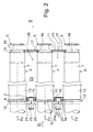
- the tube structure P shown in Fig. 1 is intended to be placed in connection with a heat exchanger, wherein the tube structure P is fixed between opposite walls 1, 2 of the flow channel VK, or the like, for a first heat transfer medium EV in the heat exchanger (Fig. 2).
- a second heat transfer medium TV is arranged to flow through the tube structure P.
- the tube structure P comprises, at its both ends 3, 4, fixing means 5, 6 for fixing the tube structure P in a releasable manner to the walls 1, 2 of the flow channel.
- the first fixing means 5 at the first end 3 is a threading which is arranged to protrude outside the first wall 1 of the flow channel VK when the tube structure P is in installed position.
- the second fixing means 6 of the tube structure P is, in turn, a collar flange located at the second end 4 of the tube structure P and protruding from its outer surface.
- the collar flange is arranged to be located outside the second wall 2 of the flow channel VK when the tube structure P is in installed position.
- the first fixing means 5 is, in the embodiment shown in the drawings, provided on the outer surface of a sleeve 8 fixed at the first end 7a of a main tube 7 which forms the actual flow channel for the second heat transfer medium TV in the tube structure P.
- a part of the sleeve 8 is placed inside the main tube 7 and the sleeve 8 is fixed, at its outer surface, to the main tube 7.
- the sleeve 8 is fixed by a welded joint 9 between the outer surface 8a of the sleeve 8 and the front surface 7b at the first end 7a of the main tube.
- the welded joint 9 forms an annular sealing surface 10, which faces the first end 3 of the tube structure P and whose outer surface is preferably conical.
- the sealing surface is sealed against a counter surface 11 in the first wall 1 and facing the flow channel VK, when the tube structure P is in installed position as shown in Fig. 2.
- the collar flange 12 forming the second fixing means 6 is placed in connection with a sleeve unit 13 attached to the outer surface of the main tube, wherein the sleeve unit 13 is placed around the main tube 7 in its longitudinal direction, to extend substantially in the flow channel VK, as shown in Fig. 2.
- the sleeve unit 13 is connected, at its end opposite to the collar flange 12, by a welded joint 14 to the outer surface of the main tube 7.
- the outer surface of the sleeve unit 13 is cylindrical, and the diameter of its preferably circular inner hole 13a is greater than the diameter of the cross-section of the outer surface of the main tube 7, the sleeve unit 13 being, substantially over its whole length, off the outer surface of the main tube 7.
- the collar flange 12 at the second end 4 of the tube structure P protrudes diagonally from the outer surface of the sleeve unit 13 and forms a sealing surface 12a by its surface facing the flow channel VK.
- the sealing surface 12a is sealed against the counter surface 15 of the second wall 2, directed away from the flow channel VK.
- the main tube structure 7 and the parts connected to it, particularly the sleeve unit 13, throughout at least those sections which are placed in the flow channel VK when the tube structure P is in installed position as shown in Fig. 2, can be coated with a coating 16 which takes into account the properties of the first heat transfer medium EV, if the materials for the main tube structure 7, the sleeve unit 13 and/or the welded joint 14 therebetween have been selected, for other reasons, in such a way that the material does not stand, or has a limited resistance to, the physical and/or chemical effects of the first heat transfer medium EV.
- the second heat transfer medium TV flowing in the tube structure P is arranged to flow into the tube structure P through the second end 4 of the tube structure P.
- the dimensions and the material and/or the coating of the sleeve construction can be selected so that the whole tubular structure P is resistant at this critical point of the heat exchanger, where the temperature difference between the first EV and second TV heat transfer media is the greatest and which thus has the greatest risk of temperatures below the dew point.
- the flow channel structure according to the invention is arranged to be used as a part of the heat exchanger to restrict the cross-sectional area for the flow of the first heat transfer medium EV.
- the closed flow channel having a closed cross-sectional shape achieved by means of the wall structure forming the flow channel structure has a first wall 1 and a second wall 2, between which one or several tube structures P are placed in the flow channel VK, the second heat transfer medium TV thus flowing through the tube structures P.
- the first 1 and second 2 walls are connected at their edges by end walls (not shown) to achieve said flow channel with a closed cross-section.
- the first 1 and second 2 walls comprise at least one compatible pair 17,18 of holes (in practical applications, however, several pairs 17, 18 of holes being placed at regular spacings in the walls 1 and 2), to place at least one tube structure P through the second hole 18 of the pair 17, 18 of holes to the flow channel structure in a sealed and releasable manner.
- each pair 17, 18 of holes is formed in such a way that the hole 17 in the first wall 1 of the flow channel structure substantially corresponds, in its diameter, to the inner diameter of the cross-sectional shape of the tube structure P at the location of the flow channel, wherein the edge of the first hole 17 facing the flow channel is provided with a counter surface 11 to be used in the sealing between the tube structure and the first wall 1, the counter surface 11 being placed in abutment with the sealing surface 10 of the tube structure P.
- the sleeve 8 fixed at the first end 7a of the main tube 7 protrudes through the first hole 17 outside the first wall 1 of the flow channel structure.
- the diameter of the second hole 18, through which the tube structure P is thus installed into the flow channel VK is equal to or greater than the greatest outer diameter of the cross-section of the tube structure P (in practice, the outer diameter of the sleeve structure 13) at the flow channel VK, wherein the edge of the second hole 18 directed away, i.e. outwards from the flow channel VK is provided with a diagonal annular counter surface 15 which is to be used in the sealing between the tube structure P and the second wall 2 and which is connected to the sealing surface 12a of the collar flange 12 when the tube structure P is in installed position.
- the heat exchanger comprises, in the above-described manner, a combination of a flow channel structure (walls 1, 2 and end walls connecting them) and at least one tube structure P placed therein.
- the tube structures P are thus installed through the second wall 2 in such a way that the first end 3 of the tube structure P is introduced from the outside of the flow channel structure through the second hole 18 into and through the flow channel VK, until the sleeve 8 meets the first hole 17 of said pair of holes, through which the sleeve 8 is led to the position shown in Fig. 2.
- the layout of the portions sealed against each other in the flow channel structure and in each tube structure P is dimensioned so that a good sealing is achieved after tightening with tightening means in the position shown in Fig. 2. If necessary, it is possible to use separate sealing materials to be placed between the sealing surfaces to secure the sealing effect accomplished with the sealing and counter surfaces (10, 11 and 12a, 15).
- the first fixing means 5 of the tube structure P is thus a threading formed on the outer surface of the sleeve 8 at the first end 3 of the tube structure P, arranged to protrude outside the first wall 1 of the flow channel VK when the tube structure P is in installed position.
- a nut 19, or the like is arranged to be installed outwardly of the heat exchanger (Fig. 3), wherein the first wall 1 of the flow channel structure is locked at the first hole 17 between the first end 3 of the tube structure P and the nut 19 or the like.
- the nut 19 serves thus in the locking of the first end 3 of the tube structure P as a tightening member acting on the tube structure in the axial direction.
- the second fixing means 6 of the tube structure P is an annular collar flange 12 located at the second end 4 of the tube structure P and protruding from its outer surface.
- the collar flange is arranged to be located outside the second wall 2 of the flow channel VK when the tube structure P is in installed position.
- a press plate 20 or the like to be installed outwardly from the heat exchanger, is arranged to be used in the fixing, wherein the collar flange 12 is locked between the second wall 2 of the flow channel VK and the press plate 20 or the like, connected to each other with a locking means 21, 22.
- the press plate 20 or the like is arranged to fix several, preferably four collar flanges 121, 122, 123, 124 belonging to different tube structures P1-P4 (such tube structures P1-P4 are next to each other in the heat exchanger) and located at fixed distance from its centre (Fig. 4).
- the locking means 21, 22 consists of a stud bolt 21, which is connected (for exmple by a threaded hole fit) to the second wall 2 of the flow channel VK, protrudes from its outer surface and is arranged to extend through a central hole 20a in the press plate 20 or the like, wherein a tightening nut 22 or the like, belonging to the locking means, is installed on the stud bolt 21 outside the press plate 20.
- the tightening nut 22 or the like and the press plate 20, which can be several for one tube structure P in the manner shown by Fig. 3, serve in the locking of the second end 4 of the tube structure P as a tightening member acting on the tube structure in the axial direction and bringing about a force effect in the tube structure in the same direction as does the tightening member (nut 19) of its opposite, first end 3.
Landscapes
- Engineering & Computer Science (AREA)
- Physics & Mathematics (AREA)
- Thermal Sciences (AREA)
- Mechanical Engineering (AREA)
- General Engineering & Computer Science (AREA)
- Heat-Exchange Devices With Radiators And Conduit Assemblies (AREA)
- Rigid Pipes And Flexible Pipes (AREA)
Applications Claiming Priority (2)
| Application Number | Priority Date | Filing Date | Title |
|---|---|---|---|
| FI20002659 | 2000-12-05 | ||
| FI20002659A FI116418B (fi) | 2000-12-05 | 2000-12-05 | Putkirakenne, virtauskanavarakenne ja lämmönvaihdin |
Publications (3)
| Publication Number | Publication Date |
|---|---|
| EP1213557A2 true EP1213557A2 (de) | 2002-06-12 |
| EP1213557A3 EP1213557A3 (de) | 2005-03-02 |
| EP1213557B1 EP1213557B1 (de) | 2007-08-08 |
Family
ID=8559642
Family Applications (1)
| Application Number | Title | Priority Date | Filing Date |
|---|---|---|---|
| EP01660221A Expired - Lifetime EP1213557B1 (de) | 2000-12-05 | 2001-12-05 | Rohranordnung, Fliesskanalstruktur und ein Wärmetauscher |
Country Status (5)
| Country | Link |
|---|---|
| EP (1) | EP1213557B1 (de) |
| AT (1) | ATE369536T1 (de) |
| DE (1) | DE60129780T2 (de) |
| ES (1) | ES2288920T3 (de) |
| FI (1) | FI116418B (de) |
Cited By (1)
| Publication number | Priority date | Publication date | Assignee | Title |
|---|---|---|---|---|
| WO2007025506A1 (de) * | 2005-08-27 | 2007-03-08 | A. Monforts Textilmaschinen Gmbh & Co. Kg | Rohrwärmetauscher |
Family Cites Families (9)
| Publication number | Priority date | Publication date | Assignee | Title |
|---|---|---|---|---|
| US1790897A (en) * | 1931-02-03 | brown | ||
| GB533935A (en) * | 1939-10-21 | 1941-02-24 | Arthur Guy Enock | Improvements in tubular heat exchangers |
| US2816739A (en) * | 1954-03-03 | 1957-12-17 | Schutte & Koerting Co | Tube and tube sheet assembly |
| GB1061854A (en) * | 1964-08-12 | 1967-03-15 | Babcock & Wilcox Ltd | Improvements in or relating to tube banks |
| GB1244911A (en) * | 1969-01-09 | 1971-09-02 | British Iron Steel Research | Improvements in and relating to ceramic recuperators |
| US4171014A (en) * | 1972-11-28 | 1979-10-16 | Sulzer Brothers Limited | Arrangement for mounting tubes in a tank wall |
| FR2243386B1 (de) * | 1973-09-07 | 1976-11-19 | Commissariat Energie Atomique | |
| JPS5671799A (en) * | 1979-11-14 | 1981-06-15 | Kaneoka Kogyo Kk | Tube and plate joining structure in multitubular heat exchanger |
| US5323849A (en) * | 1993-04-21 | 1994-06-28 | The United States Of America As Represented By The Secretary Of The Navy | Corrosion resistant shell and tube heat exchanger and a method of repairing the same |
-
2000
- 2000-12-05 FI FI20002659A patent/FI116418B/fi not_active IP Right Cessation
-
2001
- 2001-12-05 ES ES01660221T patent/ES2288920T3/es not_active Expired - Lifetime
- 2001-12-05 AT AT01660221T patent/ATE369536T1/de active
- 2001-12-05 DE DE60129780T patent/DE60129780T2/de not_active Expired - Lifetime
- 2001-12-05 EP EP01660221A patent/EP1213557B1/de not_active Expired - Lifetime
Cited By (1)
| Publication number | Priority date | Publication date | Assignee | Title |
|---|---|---|---|---|
| WO2007025506A1 (de) * | 2005-08-27 | 2007-03-08 | A. Monforts Textilmaschinen Gmbh & Co. Kg | Rohrwärmetauscher |
Also Published As
| Publication number | Publication date |
|---|---|
| ES2288920T3 (es) | 2008-02-01 |
| ATE369536T1 (de) | 2007-08-15 |
| FI20002659L (fi) | 2002-06-06 |
| FI20002659A0 (fi) | 2000-12-05 |
| EP1213557B1 (de) | 2007-08-08 |
| DE60129780T2 (de) | 2007-12-06 |
| DE60129780D1 (de) | 2007-09-20 |
| FI116418B (fi) | 2005-11-15 |
| EP1213557A3 (de) | 2005-03-02 |
Similar Documents
| Publication | Publication Date | Title |
|---|---|---|
| US8967234B2 (en) | Tube plug for a heat exchanger tube | |
| US6957695B2 (en) | Heat exchanger housing and seals | |
| KR20150067054A (ko) | 직관 구성을 갖는 관다발 열 교환기, 프로세스 가스 냉각기, 가스 터빈 냉기용 냉각기, 가스 터빈 또는 가스 및 증기 터빈 발전소, 및 냉기의 냉각 방법 | |
| EP1038147B1 (de) | Plattenwärmetauscher | |
| US5181561A (en) | Stiffener for use with a heat exchanger | |
| EP1213557B1 (de) | Rohranordnung, Fliesskanalstruktur und ein Wärmetauscher | |
| JP5254954B2 (ja) | 管状熱交換器の内部チューブシートのシーリング構造 | |
| JP2013092260A (ja) | 廃熱ボイラ | |
| RU2008605C1 (ru) | Теплообменник | |
| CN214891854U (zh) | 原油水套加热炉 | |
| US4540184A (en) | Sand-filled sealing structure between at least one tube and a tube support plate | |
| CN1153550A (zh) | 船用锅炉 | |
| JPH0245120B2 (de) | ||
| US4538678A (en) | Heat exchanging device | |
| US4671343A (en) | Heat exchanger having spirally wound tubes | |
| US5265918A (en) | High pressure ceramic joint | |
| CN219995977U (zh) | 一种单管程浮头式换热器 | |
| JPH0735186Y2 (ja) | セラミックス配管の継手構造 | |
| KR102606645B1 (ko) | 열교환기의 유로연결수단 | |
| US20240175647A1 (en) | Ceramic tube plug | |
| CN220602262U (zh) | 一种换热器及其管板焊接结构 | |
| JP4108335B2 (ja) | 熱交換器 | |
| JP7313215B2 (ja) | 管寄せ管台及びボイラ | |
| JPH0113271Y2 (de) | ||
| CN119164222A (zh) | 一种单管程浮头式换热器 |
Legal Events
| Date | Code | Title | Description |
|---|---|---|---|
| PUAI | Public reference made under article 153(3) epc to a published international application that has entered the european phase |
Free format text: ORIGINAL CODE: 0009012 |
|
| AK | Designated contracting states |
Kind code of ref document: A2 Designated state(s): AT BE CH CY DE DK ES FI FR GB GR IE IT LI LU MC NL PT SE TR |
|
| AX | Request for extension of the european patent |
Free format text: AL;LT;LV;MK;RO;SI |
|
| RAP1 | Party data changed (applicant data changed or rights of an application transferred) |
Owner name: KVAERNER POWER OY |
|
| PUAL | Search report despatched |
Free format text: ORIGINAL CODE: 0009013 |
|
| AK | Designated contracting states |
Kind code of ref document: A3 Designated state(s): AT BE CH CY DE DK ES FI FR GB GR IE IT LI LU MC NL PT SE TR |
|
| AX | Request for extension of the european patent |
Extension state: AL LT LV MK RO SI |
|
| 17P | Request for examination filed |
Effective date: 20050830 |
|
| AKX | Designation fees paid |
Designated state(s): AT BE CH CY DE DK ES FI FR GB GR IE IT LI LU MC NL PT SE TR |
|
| GRAP | Despatch of communication of intention to grant a patent |
Free format text: ORIGINAL CODE: EPIDOSNIGR1 |
|
| GRAS | Grant fee paid |
Free format text: ORIGINAL CODE: EPIDOSNIGR3 |
|
| GRAA | (expected) grant |
Free format text: ORIGINAL CODE: 0009210 |
|
| RAP1 | Party data changed (applicant data changed or rights of an application transferred) |
Owner name: METSO POWER OY |
|
| AK | Designated contracting states |
Kind code of ref document: B1 Designated state(s): AT BE CH CY DE DK ES FI FR GB GR IE IT LI LU MC NL PT SE TR |
|
| REG | Reference to a national code |
Ref country code: GB Ref legal event code: FG4D |
|
| REG | Reference to a national code |
Ref country code: CH Ref legal event code: EP |
|
| REG | Reference to a national code |
Ref country code: IE Ref legal event code: FG4D |
|
| REF | Corresponds to: |
Ref document number: 60129780 Country of ref document: DE Date of ref document: 20070920 Kind code of ref document: P |
|
| REG | Reference to a national code |
Ref country code: SE Ref legal event code: TRGR |
|
| ET | Fr: translation filed | ||
| PG25 | Lapsed in a contracting state [announced via postgrant information from national office to epo] |
Ref country code: NL Free format text: LAPSE BECAUSE OF FAILURE TO SUBMIT A TRANSLATION OF THE DESCRIPTION OR TO PAY THE FEE WITHIN THE PRESCRIBED TIME-LIMIT Effective date: 20070808 Ref country code: FI Free format text: LAPSE BECAUSE OF FAILURE TO SUBMIT A TRANSLATION OF THE DESCRIPTION OR TO PAY THE FEE WITHIN THE PRESCRIBED TIME-LIMIT Effective date: 20070808 |
|
| NLV1 | Nl: lapsed or annulled due to failure to fulfill the requirements of art. 29p and 29m of the patents act | ||
| REG | Reference to a national code |
Ref country code: ES Ref legal event code: FG2A Ref document number: 2288920 Country of ref document: ES Kind code of ref document: T3 |
|
| REG | Reference to a national code |
Ref country code: CH Ref legal event code: PL |
|
| PG25 | Lapsed in a contracting state [announced via postgrant information from national office to epo] |
Ref country code: LI Free format text: LAPSE BECAUSE OF FAILURE TO SUBMIT A TRANSLATION OF THE DESCRIPTION OR TO PAY THE FEE WITHIN THE PRESCRIBED TIME-LIMIT Effective date: 20070808 Ref country code: CH Free format text: LAPSE BECAUSE OF FAILURE TO SUBMIT A TRANSLATION OF THE DESCRIPTION OR TO PAY THE FEE WITHIN THE PRESCRIBED TIME-LIMIT Effective date: 20070808 |
|
| PG25 | Lapsed in a contracting state [announced via postgrant information from national office to epo] |
Ref country code: BE Free format text: LAPSE BECAUSE OF FAILURE TO SUBMIT A TRANSLATION OF THE DESCRIPTION OR TO PAY THE FEE WITHIN THE PRESCRIBED TIME-LIMIT Effective date: 20070808 |
|
| PG25 | Lapsed in a contracting state [announced via postgrant information from national office to epo] |
Ref country code: DK Free format text: LAPSE BECAUSE OF FAILURE TO SUBMIT A TRANSLATION OF THE DESCRIPTION OR TO PAY THE FEE WITHIN THE PRESCRIBED TIME-LIMIT Effective date: 20070808 Ref country code: GR Free format text: LAPSE BECAUSE OF FAILURE TO SUBMIT A TRANSLATION OF THE DESCRIPTION OR TO PAY THE FEE WITHIN THE PRESCRIBED TIME-LIMIT Effective date: 20071109 |
|
| PG25 | Lapsed in a contracting state [announced via postgrant information from national office to epo] |
Ref country code: PT Free format text: LAPSE BECAUSE OF FAILURE TO SUBMIT A TRANSLATION OF THE DESCRIPTION OR TO PAY THE FEE WITHIN THE PRESCRIBED TIME-LIMIT Effective date: 20080108 |
|
| PLBE | No opposition filed within time limit |
Free format text: ORIGINAL CODE: 0009261 |
|
| STAA | Information on the status of an ep patent application or granted ep patent |
Free format text: STATUS: NO OPPOSITION FILED WITHIN TIME LIMIT |
|
| 26N | No opposition filed |
Effective date: 20080509 |
|
| PG25 | Lapsed in a contracting state [announced via postgrant information from national office to epo] |
Ref country code: MC Free format text: LAPSE BECAUSE OF NON-PAYMENT OF DUE FEES Effective date: 20071231 |
|
| PG25 | Lapsed in a contracting state [announced via postgrant information from national office to epo] |
Ref country code: IE Free format text: LAPSE BECAUSE OF NON-PAYMENT OF DUE FEES Effective date: 20071205 |
|
| PG25 | Lapsed in a contracting state [announced via postgrant information from national office to epo] |
Ref country code: CY Free format text: LAPSE BECAUSE OF FAILURE TO SUBMIT A TRANSLATION OF THE DESCRIPTION OR TO PAY THE FEE WITHIN THE PRESCRIBED TIME-LIMIT Effective date: 20070808 |
|
| PG25 | Lapsed in a contracting state [announced via postgrant information from national office to epo] |
Ref country code: LU Free format text: LAPSE BECAUSE OF NON-PAYMENT OF DUE FEES Effective date: 20071205 |
|
| PG25 | Lapsed in a contracting state [announced via postgrant information from national office to epo] |
Ref country code: TR Free format text: LAPSE BECAUSE OF FAILURE TO SUBMIT A TRANSLATION OF THE DESCRIPTION OR TO PAY THE FEE WITHIN THE PRESCRIBED TIME-LIMIT Effective date: 20070808 |
|
| PG25 | Lapsed in a contracting state [announced via postgrant information from national office to epo] |
Ref country code: IT Free format text: LAPSE BECAUSE OF NON-PAYMENT OF DUE FEES Effective date: 20071231 |
|
| PGFP | Annual fee paid to national office [announced via postgrant information from national office to epo] |
Ref country code: SE Payment date: 20121220 Year of fee payment: 12 Ref country code: GB Payment date: 20121220 Year of fee payment: 12 |
|
| PGFP | Annual fee paid to national office [announced via postgrant information from national office to epo] |
Ref country code: AT Payment date: 20121212 Year of fee payment: 12 |
|
| PGFP | Annual fee paid to national office [announced via postgrant information from national office to epo] |
Ref country code: DE Payment date: 20121220 Year of fee payment: 12 Ref country code: FR Payment date: 20130130 Year of fee payment: 12 Ref country code: ES Payment date: 20121226 Year of fee payment: 12 |
|
| REG | Reference to a national code |
Ref country code: DE Ref legal event code: R119 Ref document number: 60129780 Country of ref document: DE |
|
| REG | Reference to a national code |
Ref country code: SE Ref legal event code: EUG |
|
| REG | Reference to a national code |
Ref country code: AT Ref legal event code: MM01 Ref document number: 369536 Country of ref document: AT Kind code of ref document: T Effective date: 20131205 |
|
| GBPC | Gb: european patent ceased through non-payment of renewal fee |
Effective date: 20131205 |
|
| PG25 | Lapsed in a contracting state [announced via postgrant information from national office to epo] |
Ref country code: SE Free format text: LAPSE BECAUSE OF NON-PAYMENT OF DUE FEES Effective date: 20131206 |
|
| REG | Reference to a national code |
Ref country code: FR Ref legal event code: ST Effective date: 20140829 |
|
| REG | Reference to a national code |
Ref country code: DE Ref legal event code: R119 Ref document number: 60129780 Country of ref document: DE Effective date: 20140701 |
|
| PG25 | Lapsed in a contracting state [announced via postgrant information from national office to epo] |
Ref country code: DE Free format text: LAPSE BECAUSE OF NON-PAYMENT OF DUE FEES Effective date: 20140701 |
|
| PG25 | Lapsed in a contracting state [announced via postgrant information from national office to epo] |
Ref country code: AT Free format text: LAPSE BECAUSE OF NON-PAYMENT OF DUE FEES Effective date: 20131205 Ref country code: GB Free format text: LAPSE BECAUSE OF NON-PAYMENT OF DUE FEES Effective date: 20131205 Ref country code: FR Free format text: LAPSE BECAUSE OF NON-PAYMENT OF DUE FEES Effective date: 20131231 |
|
| REG | Reference to a national code |
Ref country code: ES Ref legal event code: FD2A Effective date: 20150406 |
|
| PG25 | Lapsed in a contracting state [announced via postgrant information from national office to epo] |
Ref country code: ES Free format text: LAPSE BECAUSE OF NON-PAYMENT OF DUE FEES Effective date: 20131206 |