EP1213739A2 - Installation fonctionnant à l'électricité pour un disjoncteur - Google Patents
Installation fonctionnant à l'électricité pour un disjoncteur Download PDFInfo
- Publication number
- EP1213739A2 EP1213739A2 EP01124382A EP01124382A EP1213739A2 EP 1213739 A2 EP1213739 A2 EP 1213739A2 EP 01124382 A EP01124382 A EP 01124382A EP 01124382 A EP01124382 A EP 01124382A EP 1213739 A2 EP1213739 A2 EP 1213739A2
- Authority
- EP
- European Patent Office
- Prior art keywords
- manual operation
- change
- operation mode
- circuit breaker
- over lever
- Prior art date
- Legal status (The legal status is an assumption and is not a legal conclusion. Google has not performed a legal analysis and makes no representation as to the accuracy of the status listed.)
- Granted
Links
Images


Classifications
-
- H—ELECTRICITY
- H01—ELECTRIC ELEMENTS
- H01H—ELECTRIC SWITCHES; RELAYS; SELECTORS; EMERGENCY PROTECTIVE DEVICES
- H01H3/00—Mechanisms for operating contacts
- H01H3/22—Power arrangements internal to the switch for operating the driving mechanism
- H01H3/227—Interlocked hand- and power-operating mechanisms
-
- H—ELECTRICITY
- H01—ELECTRIC ELEMENTS
- H01H—ELECTRIC SWITCHES; RELAYS; SELECTORS; EMERGENCY PROTECTIVE DEVICES
- H01H71/00—Details of the protective switches or relays covered by groups H01H73/00 - H01H83/00
- H01H71/10—Operating or release mechanisms
- H01H71/66—Power reset mechanisms
- H01H71/70—Power reset mechanisms actuated by electric motor
Definitions
- This invention relates to an apparatus for electrically operating a circuit breaker and, more particularly, to an apparatus for switching an operating handle of a circuit breaker by electrical or manual operation.
- a circuit breaker which is a device for interrupting a fault current such as a short-circuiting current flowing through an electrical circuit as an overcurrent, is equipped with an electrically operating apparatus which achieves the circuit interruption.
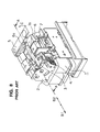
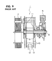
- FIG. 8 An example of the apparatus for electrically operating a circuit breaker of such type can be found in Japanese Patent Laid-Open No. 6-251687 (or U.S. Patent No. 5,504,290) and is shown in Figs. 8 and 9.
- the reference numeral 1 is an electrically operating apparatus including a drive motor 2
- 3 is a change-over lever for shifting between a manual operation mode and an electrical operation mode
- the switching of the change-over switch 4 can be achieved by sliding the change-over lever 3 into the direction of an arrow B1 or an arrow B2 (to the left or right in Fig. 8).
- the reference numeral 5 is a manual operation handle for manually opening the circuit breaker
- 6 is an ON button for closing the circuit breaker
- 7 is a TRIP button for opening the circuit breaker
- 8 is a main shaft for transmitting the operational force from the drive motor 2 and the manual operation handle 5
- 9 are cams mounted on the main shaft 8
- 10 are drive levers for transmitting a drive force on the main shaft 8 through the cams
- 11 are rollers rotatably mounted to the drive levers 10 and brought into contact with the cams
- 13 is an actuating pin secured to the drive levers 9
- 12 is an operation handle engaging the actuating pin 13.
- the change-over switch 4 is closed to establish the electrical operation mode.
- the circuit breaker can be opened or closed by energizing the drive motor 2 by remote control to rotate the main shaft 8.
- the change-over lever 3 engages with an engagement portion 6a disposed on the ON button 6 and an engagement portion 7a disposed on the TRIP button 7. Therefore, the ON button 6 and the TRIP button 7 are prevented from moving further by the change-over lever 3.
- the manual operation handle 5 does not have any structure that is restricted by the change-over lever 3, so that the manual operation handle 5 is in the state in which it can be freely operated.
- the manual operation handle 5 is not prevented from moving by the change-over lever 5 even when the circuit breaker is being remote controlled by the drive force of the drive motor 2 in the electrical operation mode, so that the manual operation handle 5 can be moved, whereby the drive motor 2 constituting the electrical operating apparatus 1 is locked and may be damaged.
- the chief object of the present invention is to provide an apparatus for electrically operating a circuit breaker free from the above discussed problems of the conventional apparatus.
- Another object of the present invention is to provide an apparatus for electrically operating a circuit breaker in which not only the ON button and the TRIP button but also the manual operation handle can be prevented from being moved during the electrical operation mode, whereby the electrical operation apparatus is not damaged and a reliable operation can be ensured.
- the present invention resides in an apparatus for electrically operating a circuit breaker, in which a control panel on a housing of the circuit breaker is provided therein a change-over lever for selectively changing between an electrical operation mode and a manual operation mode, and in which the circuit breaker is operated between the open and closed positions by a drive force from a drive motor during the electrical operation mode and the circuit breaker is operated between the open and closed positions by a drive force from a manual operation handle during the manual operation mode.
- the apparatus is arranged such that the change-over lever moves between an electrical operation mode position corresponding to the electrical operation mode and a manual operation mode position corresponding to the manual operation mode, and that the change-over lever has provided therewith a blocking portion which, while allowing the operation of the manual operation handle when the change-over lever is in the manual operation mode position, engages the manual operation handle to prevent the operation of the manual operation handle when the change-over lever is at the electrical operation mode position.
- the control panel may comprise an ON button for closing the circuit breaker in the manual operation mode and a TRIP button for opening the circuit breaker in the manual operation mode
- the change-over lever may be provided with a first engagement portion and a second engagement portion engaging the ON button and the TRIP button to prevent the operations of the ON button and the TRIP button when the change-over lever is shifted into the electrical operation mode.
- the change-over lever may have the blocking portion, the first engagement portion and the second engagement portion provided thereon as an integral and unitary structure.
- apparatus for electrically operating a circuit breaker may further comprise a switch disposed in the vicinity of the change-over lever for controlling electric current supply to the drive motor in response to the position of the change-over lever, the switch supplying the current to the drive motor when the change-over lever is in the electrical operation mode position and supplying no current to the drive motor when the change-over lever is in the manual operation mode.
- the manual operation handle may comprise a first link mounted to an energy charging means actuating shaft for actuating energy charging means, a second link pivotally connected to the first link and a spring for biasing the second link toward the position in which the second link is housed within the housing of the electrically operating apparatus, and the arrangement may be such that, when the manual operation handle is operated, the first link is rotated over a first rotation range in which the first link is rotated against the action of the spring until it engages with the second link as well as a second rotation range in which the first link, together with the second link, drives the energy charging means actuating shaft.
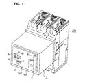
- FIGs. 1 to 7 illustrate one embodiment of the apparatus for operating a circuit breaker of the present invention and the same reference numerals indicate identical or corresponding components to those of the conventional apparatus explained in conjunction with Figs. 8 and 9.
- the reference numeral 1 indicates an electrical operating appratus
- 100 is a circuit breaker disposed at the back of the electrical operating apparatus 100
- 101 is a housing of the electrical operating apparatus.
- Disposed within the interior of the housing 101 are a drive motor 2 for electrically operating the circuit breaker 100, a change-over lever 3, a switch 4 disposed in the vicinity of the change-over lever 3 for controlling the electric current supply to the drive motor 2, an ON button 6 for closing the circuit breaker 100, a TRIP button 7 for tripping the circuit breaker 100, a transmission gear unit 70 for transmitting a drive force generated by the drive motor 2, a mechanism unit 80 and a manual operation handle device 30 having a manual operation handle 5 for mannually operating the circuit breaker 100.
- an operation panel 102 Disposed on the front of the housing 101 is an operation panel 102 (not shown in Fig. 7) having formed therein guide windows 31, 51 and 71 for guiding and supporting various operating members. Within these guide windows, the operating members are disposed, operating members including the change-over lever 3 for shifting the switch 4 which supplies an electric current to the drive motor 2 during the operation in the electrical operation mode and which does not supply the electric current to the drive motor 2 during the operation in the manual operation mode is disposed and, similarly, the manual operation handle 5 for operating the manual operation handle device 30, the ON button 6, the TRIP button and the like.
- the operating knob 3a provided on the change-over lever 3 is movable up and down with respect to the window 31 and when it is moved upward the change-over lever 3 is brought into the electrical operation mode position and when it is moved down ward the change-over lever 3 is slid into the manual operation mode position.
- the manual operation handle 5 is accommodated within the guide window 51 so that its outer surface is substantially flash with the surface of the operating panel 102 and, when the manual operation handle 5 it to be operated, it is rotated outwardly from its retracted position and guided by the window 51.
- the ON button 6 and the TRIP button 7 are guided by the windows 61 and 71, respectively, to be depressed back ward.
- the reference numeral 12 designates an operational handle for opening and closing the contacts (not shown) of the circuit breaker 100, and 13 and 14 are actuating pins constituting a mechanism portion 80 for making a reciprocating up and down motion (Fig. 2) of the operational handle 12.
- the change-over lever 3 is a substantially L-shaped member made of a thermoplastic resin material, which has integrally formed as a unitary structure, in addition to the above-mentioned operating knob 3a for the sliding movement of the change-over lever 3, a step portion 3b in the form of a recess, a first engagement portion 3c for engaging with the ON button 6 to prevent the operation of the ON button 6, a second engagement portion 3d for engaging the TRIP button 7 to prevent the operation of the TRIP button 7, and a block portion 3e for engaging the manual operation handle 5 to prevent the movement of the manual operation handle 5.
- the step portion 3b is formed in the back of the change-over lever 3 and is engageable with the lever 4a of the switch 4 so that the change-over switch 4 may be closed or opened.
- the lever 4a falls within the step portion 3b and closes the change-over switch 4 so that an electric current can be supplied to the drive motor 2.
- the change-over lever 3 When the change-over lever 3 is shifted into the electrical operation mode, the change-over lever 3 enters behind, as viewed from the control panel 102, the ON button 6, the TRIP button 7 and the tip portion 5a of the manual operation handle 5, so that the first engagement portion 3c, the second engagement portion 3d and the block portion 3e establish overlapping portions (illustrated by the hatched portion in Fig. 2) that overlap with the change-over lever 3, whereby the depression of the buttons 6 and 7 and the driving (Fig. 4) of the manual operation handle 5 is restricted to prevent the respective operations.
- the manual operation handle 5 comprises a first link 53 connected to an energy charging means actuation shaft 52 causing energy charging means such as an illustrated charging spring, a second link 55 pivotally connected through a pin 54 to the first link 53, a spring 56 connected between the first and the second links 53 and 55 for biasing the second link 55 for rotation in the clockwise direction, a projection portion 57 formed in the second link 55 for engagement with the first link 53, a ratchet wheel 58 co-axially disposed with the energy charging means actuation shaft 52 and a pawl 59 pivotally attached to the first link 53 and engaging with the teeth of the ratchet wheel 58.
- energy charging means such as an illustrated charging spring
- a second link 55 pivotally connected through a pin 54 to the first link 53
- a spring 56 connected between the first and the second links 53 and 55 for biasing the second link 55 for rotation in the clockwise direction
- a projection portion 57 formed in the second link 55 for engagement with the first link 53
- a ratchet wheel 58 co
- the pawl 59 While the pawl 59 is engaged by an end portion of the above-mentioned spring 56 and is biased for rotation in the counterclockwise direction, the pawl 59 is allowed to escape from the ratchet wheel 58 by being forcedly rotated in the clockwise direction against the spring 56.
- An elongated hole 60 is provided for allowing the pawl 59 to be forcedly rotated in the clockwise direction.
- the second lever 55 can be rotated clockwise through a first rotation range F1 about the pin 54 against the action of the spring 56 until the projection portion 57 abuts against the first lever 53. Then, the second lever 55 together with the first lever 53 is further rotated about the charging means actuation shaft 52 until it abuts against the stopper through a second rotation range F2. Then, by repeated rotational driving of the levers within the second rotational range F2 through the use of the engaging action between the ratchet wheel 58 and the pawl 59, the energy of the driving force can charged in the energy charging means.
- the first engagement portion 3c and the second engagement portion 3d integrally formed in the change-over lever 3 advance toward and overlap with the ON button 6 and the TRIP button 7, respectively.
- the block portion 3e moves toward and overlaps with the tip portion 5a of the manual operation handle 5 (the hatched portion of Fig. 2).
- the ON button 6, the TRIP button 7 and the manual operation handle 5 are brought into engagement with the first engagement portion 3c, the second engagement portion 3d and the blocking portion 3e, respectively, whereby they are caught and broght into the state in which they are prevented from being operated.
- the drive motor 2 is driven by remote operation, the drive force generated is transmitted to the mechanism portion 80 through the transmission gear 70.
- the actuating pins 13 and 14 of the mechanism portion 80 moves the operation handle 12 in the up and down directions (Fig. 2), thereby causing the circuit breaker 100 to open or close.
- the first engagement portion 3c and the second engagement portion 3d of the change-over lever 3 retreat from the ON button 6 and the TRIP button 7 to come our of engagement therefrom.
- the blocking portion 3e of the change-over lever 3 retreats from the tip portion 5a of the manual operation handle 5 to disengage therefrom.
- the energy charging means actuating shaft 52 can be driven to charge the unillustrated charign spring and moving the operating knob 12 of the circuit breaker 100 by the actuating pin 13 to open the circuit breaker.
- the electrical operation can be ensured to be prevented because no electrical current is supplied to the drive motor 2 due to the switching function of the switch 4.
- the operations of not only the ON button 6, the TRIP button 7 but also the manual operation handle 5 can be prevented, the damages to the electrical operating unit 1 can be prevented, resulting in an advantage that a highly reliable electrical operating unit for a circuit breaker can be provided.
- the change-over lever 3 has integrally and unitary formed therein the first engagement portion 3c, the second engagement portion 3d and the blocking portion 3e, the structure of the electrically operating apparatus can be advantageously simplified.
- the drive motor 2 in the manual operation mode was about to erroneously operated by remote operation by the switch 4 responsive to the change-over lever 3, the drive motor will not be driven because no electric current is supplied, avoiding an erroneous operation.
- the manual operation handle 5 is composed of the first lever 53 and the second lever 55 foldably pin-connected, so that the space in which the manual operation handle can be accommodated within the housing 101 can be made small, the overall dimensions of the electrically operating apparatus 1 can be made smaller.
- the apparatus for electrically operating a circuit breaker is arranged such that the change-over lever moves between an electrical operation mode position corresponding to the electrical operation mode and a manual operation mode position corresponding to the manual operation mode, and that the change-over lever has provided therewith a blocking portion which, while allowing the operation of the manual operation handle when the change-over lever is in the manual operation mode position, engages the manual operation handle to prevent the operation of the manual operation handle when the change-over lever is at the electrical operation mode position. Therefore, the operation of the manual operation handle in the electrical operation mode can be ensured to be prevented, avoiding the damages to the electrical operating apparatus, thsu enabling to provide a highly reliable apparatus for electrically operating a circuit breaker.
- control panel may comprise an ON button for closing the circuit breaker in the manual operation mode and a TRIP button for opening the circuit breaker in the manual operation mode
- the change-over lever may be provided with a first engagement portion and a second engagement portion engaging the ON button and the TRIP button to prevent the operations of the ON button and the TRIP button when the change-over lever is shifted into the electrical operation mode. Therefore, erroneous operation can be prevented by preventing the button operation, allowing the remote operation in the electrical operation mode to be smoothly achieved.
- the change-over lever may have the blocking portion, the first engagement portion and the second engagement portion provided thereon as an integral and unitary structure, so that the levers have simpler structures and the structure of the electrically operating apparatus can be made simpler.
- apparatus for electrically operating a circuit breaker may further comprise a switch disposed in the vicinity of the change-over lever for controlling electric current supply to the drive motor in response to the position of the change-over lever, the switch supplying the current to the drive motor when the change-over lever is in the electrical operation mode position and supplying no current to the drive motor when the change-over lever is in the manual operation mode, so that when the drive motor was to be erroneously driven by remote operation while the apparatus is being operated in the manual operation mode, the motor will not be driven because the switch is off, resulting in an advantageous result that the manual operation mode can be smoothly achieved.
- the manual operation handle may comprise a first link mounted to an energy charging means actuating shaft for actuating energy charging means, a second link pivotally connected to the first link and a spring for biasing the second link toward the position in which the second link is housed within the housing of the electrically operating apparatus, and the arrangement may be such that, when the manual operation handle is operated, the first link is rotated over a first rotation range in which the first link is rotated against the action of the spring until it engages with the second link as well as a second rotation range in which the first link, together with the second link, drives the energy charging means actuating shaft. Therefore, the manual operation handle can be retracted into the electrically operating apparatus housing, with the first and the second links of the handle folded, so that the accommodation space can be made small and the electrically operating apparatus can advantageously be made compact.
Landscapes
- Breakers (AREA)
- Switch Cases, Indication, And Locking (AREA)
- Mechanisms For Operating Contacts (AREA)
Applications Claiming Priority (2)
| Application Number | Priority Date | Filing Date | Title |
|---|---|---|---|
| JP2000374322 | 2000-12-08 | ||
| JP2000374322A JP4443025B2 (ja) | 2000-12-08 | 2000-12-08 | 回路遮断器の電動操作装置 |
Publications (3)
| Publication Number | Publication Date |
|---|---|
| EP1213739A2 true EP1213739A2 (fr) | 2002-06-12 |
| EP1213739A3 EP1213739A3 (fr) | 2004-04-07 |
| EP1213739B1 EP1213739B1 (fr) | 2007-07-18 |
Family
ID=18843532
Family Applications (1)
| Application Number | Title | Priority Date | Filing Date |
|---|---|---|---|
| EP01124382A Expired - Lifetime EP1213739B1 (fr) | 2000-12-08 | 2001-10-24 | Installation fonctionnant à l'électricité pour un disjoncteur |
Country Status (5)
| Country | Link |
|---|---|
| US (1) | US6489577B2 (fr) |
| EP (1) | EP1213739B1 (fr) |
| JP (1) | JP4443025B2 (fr) |
| DE (1) | DE60129401T2 (fr) |
| ES (1) | ES2287062T3 (fr) |
Cited By (1)
| Publication number | Priority date | Publication date | Assignee | Title |
|---|---|---|---|---|
| CN109360754A (zh) * | 2018-11-06 | 2019-02-19 | 安士缔(中国)电气设备有限公司 | 一种应用于两台断路器的星三角电气回路操作装置 |
Families Citing this family (12)
| Publication number | Priority date | Publication date | Assignee | Title |
|---|---|---|---|---|
| USD807304S1 (en) | 2004-04-08 | 2018-01-09 | Abb S.P.A. | Circuit breaker panel |
| USD562777S1 (en) | 2004-04-08 | 2008-02-26 | Abb Service S.R.L. | Circuit breaker |
| US7279651B1 (en) * | 2004-07-01 | 2007-10-09 | Bill Nguyen | Automatic shut-off switch for main power source |
| WO2006119161A1 (fr) * | 2005-05-02 | 2006-11-09 | Carling Technologies, Inc. | Commande de disjoncteur actionne a distance montable |
| USD587658S1 (en) * | 2005-05-10 | 2009-03-03 | Abb S.P.A. | Circuit breaker |
| US8032260B2 (en) * | 2005-11-30 | 2011-10-04 | General Electric Company | Method and system for controlling a power distribution system |
| US20070159746A1 (en) | 2005-12-30 | 2007-07-12 | General Electric Company | Centrally controlled protection systems having reduced energy let-through mode |
| USD633446S1 (en) | 2009-02-06 | 2011-03-01 | Abb S.P.A. | Circuit breaker |
| KR200477244Y1 (ko) * | 2011-02-22 | 2015-05-22 | 엘에스산전 주식회사 | 배선용 차단기 |
| USD752524S1 (en) | 2012-11-09 | 2016-03-29 | Abb S.P.A. | Circuit breaker |
| USD1008982S1 (en) | 2020-07-16 | 2023-12-26 | Schneider Electric Industries Sas | Contactor |
| USD1005970S1 (en) | 2020-07-16 | 2023-11-28 | Schneider Electric Industries Sas | Overload relay |
Family Cites Families (10)
| Publication number | Priority date | Publication date | Assignee | Title |
|---|---|---|---|---|
| JPS6412335U (fr) | 1987-07-13 | 1989-01-23 | ||
| FR2654254B1 (fr) * | 1989-11-06 | 1995-11-24 | Merlin Gerin | Dispositif de telecommande pour disjoncteur electrique. |
| US5196658A (en) * | 1991-05-31 | 1993-03-23 | Westinghouse Electric Corp. | Integral manual on/off crank assembly |
| FR2701596B1 (fr) | 1993-02-16 | 1995-04-14 | Merlin Gerin | Disjoncteur télécommande à came de réarmement. |
| US5575381A (en) * | 1994-09-30 | 1996-11-19 | General Electric Company | Interlock for high ampere-rated circuit breaker contact closing springs |
| US5700985A (en) * | 1996-02-29 | 1997-12-23 | Eaton Corporation | Interlock latch for electrical operator |
| US5762181A (en) * | 1996-08-05 | 1998-06-09 | General Electric Company | Means to control the operating cycle of an electric motor operator for high ampere-rated circuit breakers |
| US6087610A (en) * | 1997-05-28 | 2000-07-11 | General Electric Company | Closing springs release mechanism for industrial-rated circuit breaker |
| US6166343A (en) * | 1999-03-29 | 2000-12-26 | Siemens Energy & Automation, Inc. | Unidirectional clutch assembly for a stored energy circuit breaker operator assembly |
| US6130392A (en) * | 1999-03-29 | 2000-10-10 | Siemens Energy & Automation, Inc. | Stored energy circuit breaker operator |
-
2000
- 2000-12-08 JP JP2000374322A patent/JP4443025B2/ja not_active Expired - Fee Related
-
2001
- 2001-10-19 US US09/981,732 patent/US6489577B2/en not_active Expired - Fee Related
- 2001-10-24 DE DE60129401T patent/DE60129401T2/de not_active Expired - Lifetime
- 2001-10-24 ES ES01124382T patent/ES2287062T3/es not_active Expired - Lifetime
- 2001-10-24 EP EP01124382A patent/EP1213739B1/fr not_active Expired - Lifetime
Cited By (2)
| Publication number | Priority date | Publication date | Assignee | Title |
|---|---|---|---|---|
| CN109360754A (zh) * | 2018-11-06 | 2019-02-19 | 安士缔(中国)电气设备有限公司 | 一种应用于两台断路器的星三角电气回路操作装置 |
| CN109360754B (zh) * | 2018-11-06 | 2024-01-19 | 安士缔(中国)电气设备有限公司 | 一种应用于两台断路器的星三角电气回路操作装置 |
Also Published As
| Publication number | Publication date |
|---|---|
| DE60129401T2 (de) | 2008-04-10 |
| EP1213739A3 (fr) | 2004-04-07 |
| US20020070103A1 (en) | 2002-06-13 |
| ES2287062T3 (es) | 2007-12-16 |
| DE60129401D1 (de) | 2007-08-30 |
| EP1213739B1 (fr) | 2007-07-18 |
| US6489577B2 (en) | 2002-12-03 |
| JP2002175753A (ja) | 2002-06-21 |
| JP4443025B2 (ja) | 2010-03-31 |
Similar Documents
| Publication | Publication Date | Title |
|---|---|---|
| JP4058895B2 (ja) | 回路しゃ断器のハンドル操作機構 | |
| US6489577B2 (en) | Electrically operating apparatus for circuit breaker | |
| US6685239B2 (en) | Vehicle door opening closing device | |
| JP2002133994A (ja) | 回路しゃ断器 | |
| JP2002147089A (ja) | スライドドアのロックコントローラ | |
| EP1544885B1 (fr) | Dispositif de poignée pour disjoncteur à commande manuelle pour moteur | |
| US6788172B1 (en) | Device for controlling the closing of a power circuit breaker | |
| CN104769696B (zh) | 开关的弹簧操作装置 | |
| JP3959941B2 (ja) | 回路しゃ断器およびその付属スイッチ | |
| US6476337B2 (en) | Auxiliary switch actuation arrangement | |
| EP0296631B1 (fr) | Appareil pour l'actionnement électrique d'un interrupteur | |
| JP4029664B2 (ja) | 回路しゃ断器 | |
| KR100516944B1 (ko) | 선행 시동형 부족전압 트립장치의 연동구조 | |
| JP2832234B2 (ja) | 車両用オートドアロック装置 | |
| KR101704432B1 (ko) | 회로차단기의 투입스프링 차징 장치 | |
| CN110914946A (zh) | 开闭器的互锁装置及开闭系统 | |
| US5521346A (en) | Sequential close interlock arrangement for high ampere-ratedcircuit breaker | |
| JPH05217485A (ja) | 回路遮断器の電気操作装置 | |
| JP2005129436A (ja) | 回路遮断器 | |
| JP2013140743A (ja) | ワイヤ式引外し装置を備えた回路遮断器 | |
| CN223911620U (zh) | 一种重合闸断路器 | |
| JP4597793B2 (ja) | 回路遮断器 | |
| JP7440903B2 (ja) | 回路遮断器の操作装置、回路遮断器ユニット及び分電盤 | |
| JP2805569B2 (ja) | 車両用オートドアロック装置 | |
| JP3952855B2 (ja) | 回路しゃ断器の付属スイッチユニット |
Legal Events
| Date | Code | Title | Description |
|---|---|---|---|
| PUAI | Public reference made under article 153(3) epc to a published international application that has entered the european phase |
Free format text: ORIGINAL CODE: 0009012 |
|
| AK | Designated contracting states |
Kind code of ref document: A2 Designated state(s): AT BE CH CY DE DK ES FI FR GB GR IE IT LI LU MC NL PT SE TR |
|
| AX | Request for extension of the european patent |
Free format text: AL;LT;LV;MK;RO;SI |
|
| PUAL | Search report despatched |
Free format text: ORIGINAL CODE: 0009013 |
|
| AK | Designated contracting states |
Kind code of ref document: A3 Designated state(s): AT BE CH CY DE DK ES FI FR GB GR IE IT LI LU MC NL PT SE TR |
|
| AX | Request for extension of the european patent |
Extension state: AL LT LV MK RO SI |
|
| 17P | Request for examination filed |
Effective date: 20040408 |
|
| AKX | Designation fees paid |
Designated state(s): DE ES GB |
|
| RAP1 | Party data changed (applicant data changed or rights of an application transferred) |
Owner name: MITSUBISHI DENKI KABUSHIKI KAISHA |
|
| GRAP | Despatch of communication of intention to grant a patent |
Free format text: ORIGINAL CODE: EPIDOSNIGR1 |
|
| RIN1 | Information on inventor provided before grant (corrected) |
Inventor name: KURATA, KOHEIMITSUBISHI ELECTRIC ENG. CO., LTD., |
|
| GRAS | Grant fee paid |
Free format text: ORIGINAL CODE: EPIDOSNIGR3 |
|
| GRAA | (expected) grant |
Free format text: ORIGINAL CODE: 0009210 |
|
| AK | Designated contracting states |
Kind code of ref document: B1 Designated state(s): DE ES GB |
|
| REG | Reference to a national code |
Ref country code: GB Ref legal event code: FG4D |
|
| REF | Corresponds to: |
Ref document number: 60129401 Country of ref document: DE Date of ref document: 20070830 Kind code of ref document: P |
|
| REG | Reference to a national code |
Ref country code: ES Ref legal event code: FG2A Ref document number: 2287062 Country of ref document: ES Kind code of ref document: T3 |
|
| PLBE | No opposition filed within time limit |
Free format text: ORIGINAL CODE: 0009261 |
|
| STAA | Information on the status of an ep patent application or granted ep patent |
Free format text: STATUS: NO OPPOSITION FILED WITHIN TIME LIMIT |
|
| 26N | No opposition filed |
Effective date: 20080421 |
|
| REG | Reference to a national code |
Ref country code: GB Ref legal event code: 746 Effective date: 20110513 |
|
| REG | Reference to a national code |
Ref country code: DE Ref legal event code: R084 Ref document number: 60129401 Country of ref document: DE Effective date: 20110701 Ref country code: DE Ref legal event code: R084 Ref document number: 60129401 Country of ref document: DE Effective date: 20110506 |
|
| REG | Reference to a national code |
Ref country code: ES Ref legal event code: GC2A Effective date: 20111027 |
|
| PGFP | Annual fee paid to national office [announced via postgrant information from national office to epo] |
Ref country code: DE Payment date: 20181009 Year of fee payment: 18 |
|
| PGFP | Annual fee paid to national office [announced via postgrant information from national office to epo] |
Ref country code: ES Payment date: 20181105 Year of fee payment: 18 Ref country code: GB Payment date: 20181024 Year of fee payment: 18 |
|
| REG | Reference to a national code |
Ref country code: DE Ref legal event code: R119 Ref document number: 60129401 Country of ref document: DE |
|
| PG25 | Lapsed in a contracting state [announced via postgrant information from national office to epo] |
Ref country code: DE Free format text: LAPSE BECAUSE OF NON-PAYMENT OF DUE FEES Effective date: 20200501 |
|
| GBPC | Gb: european patent ceased through non-payment of renewal fee |
Effective date: 20191024 |
|
| PG25 | Lapsed in a contracting state [announced via postgrant information from national office to epo] |
Ref country code: GB Free format text: LAPSE BECAUSE OF NON-PAYMENT OF DUE FEES Effective date: 20191024 |
|
| REG | Reference to a national code |
Ref country code: ES Ref legal event code: FD2A Effective date: 20210414 |
|
| PG25 | Lapsed in a contracting state [announced via postgrant information from national office to epo] |
Ref country code: ES Free format text: LAPSE BECAUSE OF NON-PAYMENT OF DUE FEES Effective date: 20191025 |