EP1213801A2 - Laserverstärkersystem - Google Patents
Laserverstärkersystem Download PDFInfo
- Publication number
- EP1213801A2 EP1213801A2 EP01129075A EP01129075A EP1213801A2 EP 1213801 A2 EP1213801 A2 EP 1213801A2 EP 01129075 A EP01129075 A EP 01129075A EP 01129075 A EP01129075 A EP 01129075A EP 1213801 A2 EP1213801 A2 EP 1213801A2
- Authority
- EP
- European Patent Office
- Prior art keywords
- amplifier system
- laser amplifier
- carrier
- solid
- solid body
- Prior art date
- Legal status (The legal status is an assumption and is not a legal conclusion. Google has not performed a legal analysis and makes no representation as to the accuracy of the status listed.)
- Granted
Links
- 239000007787 solid Substances 0.000 claims abstract description 180
- 230000005855 radiation Effects 0.000 claims abstract description 52
- 239000002826 coolant Substances 0.000 claims abstract description 41
- 238000001816 cooling Methods 0.000 claims abstract description 30
- 239000012530 fluid Substances 0.000 claims abstract description 15
- 239000011149 active material Substances 0.000 claims abstract description 10
- 238000005086 pumping Methods 0.000 claims abstract description 3
- 239000010410 layer Substances 0.000 claims description 97
- 230000003287 optical effect Effects 0.000 claims description 20
- 239000000463 material Substances 0.000 claims description 18
- 239000012528 membrane Substances 0.000 claims description 15
- 230000003667 anti-reflective effect Effects 0.000 claims description 6
- 230000009471 action Effects 0.000 claims description 4
- 239000013078 crystal Substances 0.000 claims description 3
- 239000011241 protective layer Substances 0.000 claims description 2
- 230000002349 favourable effect Effects 0.000 description 10
- 230000008901 benefit Effects 0.000 description 9
- 239000011248 coating agent Substances 0.000 description 9
- 238000000576 coating method Methods 0.000 description 9
- 230000000694 effects Effects 0.000 description 6
- 230000002411 adverse Effects 0.000 description 3
- 230000008859 change Effects 0.000 description 2
- 230000017525 heat dissipation Effects 0.000 description 2
- 230000010354 integration Effects 0.000 description 2
- 230000036316 preload Effects 0.000 description 2
- 125000006850 spacer group Chemical group 0.000 description 2
- 230000001154 acute effect Effects 0.000 description 1
- 230000015572 biosynthetic process Effects 0.000 description 1
- 239000003795 chemical substances by application Substances 0.000 description 1
- 239000002131 composite material Substances 0.000 description 1
- 230000006735 deficit Effects 0.000 description 1
- 238000009792 diffusion process Methods 0.000 description 1
- 230000005284 excitation Effects 0.000 description 1
- 238000010438 heat treatment Methods 0.000 description 1
- 238000009413 insulation Methods 0.000 description 1
- 230000003993 interaction Effects 0.000 description 1
- 230000000149 penetrating effect Effects 0.000 description 1
- 230000002093 peripheral effect Effects 0.000 description 1
- 230000009467 reduction Effects 0.000 description 1
- 230000002787 reinforcement Effects 0.000 description 1
- 238000007789 sealing Methods 0.000 description 1
- 238000007493 shaping process Methods 0.000 description 1
- 239000000126 substance Substances 0.000 description 1
- 239000012780 transparent material Substances 0.000 description 1
Images


Classifications
-
- H—ELECTRICITY
- H01—ELECTRIC ELEMENTS
- H01S—DEVICES USING THE PROCESS OF LIGHT AMPLIFICATION BY STIMULATED EMISSION OF RADIATION [LASER] TO AMPLIFY OR GENERATE LIGHT; DEVICES USING STIMULATED EMISSION OF ELECTROMAGNETIC RADIATION IN WAVE RANGES OTHER THAN OPTICAL
- H01S3/00—Lasers, i.e. devices using stimulated emission of electromagnetic radiation in the infrared, visible or ultraviolet wave range
- H01S3/05—Construction or shape of optical resonators; Accommodation of active medium therein; Shape of active medium
- H01S3/06—Construction or shape of active medium
- H01S3/0602—Crystal lasers or glass lasers
- H01S3/0604—Crystal lasers or glass lasers in the form of a plate or disc
-
- H—ELECTRICITY
- H01—ELECTRIC ELEMENTS
- H01S—DEVICES USING THE PROCESS OF LIGHT AMPLIFICATION BY STIMULATED EMISSION OF RADIATION [LASER] TO AMPLIFY OR GENERATE LIGHT; DEVICES USING STIMULATED EMISSION OF ELECTROMAGNETIC RADIATION IN WAVE RANGES OTHER THAN OPTICAL
- H01S3/00—Lasers, i.e. devices using stimulated emission of electromagnetic radiation in the infrared, visible or ultraviolet wave range
- H01S3/02—Constructional details
- H01S3/025—Constructional details of solid state lasers, e.g. housings or mountings
-
- H—ELECTRICITY
- H01—ELECTRIC ELEMENTS
- H01S—DEVICES USING THE PROCESS OF LIGHT AMPLIFICATION BY STIMULATED EMISSION OF RADIATION [LASER] TO AMPLIFY OR GENERATE LIGHT; DEVICES USING STIMULATED EMISSION OF ELECTROMAGNETIC RADIATION IN WAVE RANGES OTHER THAN OPTICAL
- H01S3/00—Lasers, i.e. devices using stimulated emission of electromagnetic radiation in the infrared, visible or ultraviolet wave range
- H01S3/02—Constructional details
- H01S3/04—Arrangements for thermal management
- H01S3/0407—Liquid cooling, e.g. by water
-
- H—ELECTRICITY
- H01—ELECTRIC ELEMENTS
- H01S—DEVICES USING THE PROCESS OF LIGHT AMPLIFICATION BY STIMULATED EMISSION OF RADIATION [LASER] TO AMPLIFY OR GENERATE LIGHT; DEVICES USING STIMULATED EMISSION OF ELECTROMAGNETIC RADIATION IN WAVE RANGES OTHER THAN OPTICAL
- H01S3/00—Lasers, i.e. devices using stimulated emission of electromagnetic radiation in the infrared, visible or ultraviolet wave range
- H01S3/02—Constructional details
- H01S3/04—Arrangements for thermal management
- H01S3/042—Arrangements for thermal management for solid state lasers
Definitions
- the invention relates to a laser amplifier system comprising one another opposite flat sides having plate-shaped Solid body, which comprises a laser-active material, one penetrating the solid body Laser radiation field, a pump radiation field pumping the laser-active material, a cooling device, which from the solid via a first flat side heat by means of a fluid cooling medium flowing in it records, and one arranged on the first flat side Reflector for the laser radiation field.
- Such a laser amplifier system is from the European patent application 0 632 551 known.
- the solid is fixed over the first flat side carrying the reflector, which is problematic is to fix the solid defined in such a way that as possible optimal optical conditions for the spread of the laser radiation field available.
- the invention is therefore based on the object of a laser amplifier system to improve the generic type in such a way that the solid as possible can be optimally arranged and aligned.
- This task is the beginning of a laser amplifier system described type according to the invention solved in that one of the laser radiation field enforced and for this transparent, dimensionally stable support it is provided for the solid body that the solid body with its second Flat surface supported flat on a support surface of the dimensionally stable support is and essentially only on the interacting with the second flat side Carrier surface is defined shape and position-defined.
- a particularly favorable solution provides that the first flat side in area penetrated by the laser radiation field free of through one in itself mechanically rigid surface is predetermined constraining forces. Avoid this solution it, especially in the area penetrated by the laser radiation field of the solid to build up mechanical stresses, which in turn the optical properties of the solid in the laser radiation field can adversely affect the enforced area.
- An advantageous embodiment of the solution according to the invention provides before that the solid is fixed to the carrier.
- a particularly favorable solution provides that the solid body on the carrier by an effective between the support surface and the second flat side Connection is fixed.
- a particularly favorable solution provides that the connection between the carrier surface and the second flat side by bonding the carrier and Solid has arisen, with the bonding of carrier and solid Establish a mechanically resilient rigid connection between the Solid body and the carrier is to be understood.
- connection between the solid and the carrier by bonding has the advantage that no additional material is used that the adversely affect the optical properties of the unit consisting of carrier and solid could.
- connection between the support surface and the second flat side is carried out by a holding layer.
- the holding layer has the disadvantage that this may have an adverse effect the optical properties of the unit consisting of carrier and solid leads, on the other hand, the advantage that the connection between the solid and can be realized in a simple manner.
- the Holding layer with respect to its refractive index to the refractive index of the Solid body is adjusted.
- a particularly favorable solution which in particular avoids reflections in the region of the holding layer, provides that there is in each case a difference in refractive index of less than 10 -2 between the holding layer and the support and / or the holding layer and the solid.
- a particularly favorable solution provides that the solid by Coolant is applied in the direction of the carrier, so that the pressure in the cooling medium itself can be used to generate the force, with which a non-positive fixation of the solid body on the carrier he follows.
- the solid body in partial areas is subjected to force in the direction of the carrier, so that by a partial application of the solid to fix the solid on Carrier done by friction.
- the solid body with the from the laser radiation field enforced partial volume adjacent area of the second Flat side at each point with essentially the same force on the beam acts, so that due to this essentially homogeneous force effect those acting on the solid and thus, if necessary, its optical Forces affecting properties no inhomogeneities with regard to optical properties in the partial volume penetrated by the laser radiation field cause.
- Another possibility of applying the solid to the support surface in a defined manner provides that the one with the second flat side on the support surface adjacent solid body, at least with that of the laser radiation field area of the second carrier surface which is penetrated by the partial volume, acts on the wearer due to internal preload. This is due to different Solutions realizable.
- Another solution provides that the second flat side before creating the same has a convex curvature on the support surface and engages a substantially flat or less convex curvature Carrier surface takes place.
- the dissipation of the heat from the solid were in Connection with the previous explanation of the individual embodiments no details given. It is preferably provided that the dissipation of heat from the solid via at least one layer system comprising the solid applied layer.
- Such a layer system could itself be cooled indirectly again. It is particularly favorable if the layer system on one of the flat sides opposite side directly acted upon by the fluid cooling medium is.
- the carrier surface hindered or mechanical stresses in the solid leads, it is preferably provided that the removal of heat the solid to the fluid cooling medium only through layers flexible materials.
- flexible materials means that the The stiffness of the layer system is significantly less than the stiffness of the support and the solid should be so as not to have any negative effects.
- the layers, via which heat is removed from the solid body to the fluid cooling medium have an overall thermal resistance of at most 8 K ⁇ mm 2 / W.
- the structure of the layer system is very different Possibilities conceivable.
- the layer system is one Has layer, which is a reflector layer, which in turn on her the back of the first flat side facing away from the cooling medium is acted upon.
- the heat dissipation by the cooling device takes place over a cover layer carried by a reflector layer, which on a side facing away from the solid body from the fluid cooling medium is acted upon.
- This cover layer is preferably a protective layer for the reflector layer trained against the influence of the cooling medium.
- the top layer itself can have a wide variety of properties. It is particularly advantageous if there is no shape-defining covering layer The solid is affected, d. H. the mechanical properties the top layer has no shape-defining effects on the Have solids.
- the cover layer is preferably designed as a flexible layer.
- the cover layer as shape-adapting layer is formed on the shape of the solid.
- the layer system Comprises membrane, which on its side facing away from the solid from is applied to the fluid cooling medium.
- the membrane preferably lies on an opposite side of the solid Side on the reflector layer or one on the reflector layer applied top layer.
- solid and Cooling device is preferably provided that the solid body with the Layer system delimits a chamber carrying the cooling medium.
- Another advantageous embodiment provides in particular that a layer of the layer system limits the chamber that carries the cooling medium.
- the cooling chamber for the cooling medium in a holder housing of a holder for the Carrier is provided so that the bracket of the carrier at the same time as Cooling device works.
- a particularly favorable solution provides that the carrier with the solid closes an opening in the holder housing, starting from the opening extends a recess which forms the cooling chamber.
- the carrier is not primarily used for the solid body to cool. Nevertheless, it is preferable, especially for the good Temperature compensation on the part of the carrier, provided that the carrier from a material with a thermal conductivity less than 2 W / m ⁇ K is formed.
- the carrier from one athermal optical material is formed, that is, a material at which the optical properties change due to temperature changes or Temperature gradients essentially do not change as the temperature changes and the geometry the calculation index changes so that the optical properties are essentially not changed.
- the Carrier to cool the solid, it is preferably provided that the carrier is essentially thermally insulated from the cooling device.
- An advantageous exemplary embodiment provides that the carrier and the solid similar crystal lattice-forming materials have so that their thermal expansion is as similar as possible and thus, when the solid is heated up, there is no markedly different thermal expansion occurs relative to the wearer.
- the flat sides of the solid are plane-parallel are polished, so that there is no negative influence on the laser radiation field when passing through the flat sides results.
- the carrier and the solid in the area of the second flat side and the support surface with one another are connected and the first flat side and one opposite the support surface Front surface of the carrier are polished parallel to each other so that in in this case, the unit consisting of carrier and solid two plane-parallel surfaces has, which is advantageous for good beam quality of the laser radiation field are.
- the carrier could also make contributions to the laser amplifier function deliver, these functional contributions from those of the laseractive Medium are dominated.
- the material of the carrier could have poor reinforcement properties for the laser radiation field.
- the functional contributions of the carrier are such that the through conditional heat input less than about 10%, better still less than approximately 5% of the heat input in the laser-active medium.
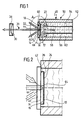
- a first embodiment of a laser amplifier system according to the invention includes one designated as a whole at 10 plate-shaped solid, with a first flat side 12, with one of these opposite flat side 14 and with one extending between the opposite flat sides 12 and 14 Narrow side 16.
- the solid body 10 in turn comprises a laser-active material, so it is doped with a laser-active material, for example.
- the solid has a partial volume penetrated by a laser radiation field 20 22, wherein the laser radiation field 20, for example, by a resonator comprising two reflectors is defined.
- a first reflector 24 is on the first flat side 12 of the solid body 10, for example in the form of a coating 26 applied directly to the first flat side 12.
- a second reflector 28 is formed by an external mirror 30, which on a side of the solid body opposite the first flat side 12 10 arranged and facing the second flat side 14, wherein for example, the external mirror 30 as the laser radiation field 20 shaping, in particular concave mirror is formed.
- the excitation of the laser-active material of the solid, at least within of the partial volume 22 takes place through a pump radiation field 32, which for example with respect to the laser radiation field 20 at an acute angle slants into the partial volume 22 and preferably also from the first reflector 24 is reflected, in order to thus a multiple pass of the To achieve the pump radiation field 32 through the partial volume 22.
- a dimensionally stable support 40 is provided, which one Has carrier surface 42 on which the solid body 10 with its second Flat side is supported flat.
- the carrier 40 is in a volume region 44 from the laser radiation field 20 penetrated and at least in this volume range, preferably overall, from one for the laser radiation field 20 and if necessary, the pump radiation field 32 is also formed of transparent material.
- the solid Due to the flat support of the solid body with its second flat side 14 on the support surface 42, the solid is supported by the support 40 on the one hand shape-defined and, on the other hand, position-defined in the laser radiation field 20 held, the carrier 40 in turn relative via a holding device 46 to the second reflector 28 is firmly positioned, so that not only the Solid 10, but also the first reflector 24 in a defined position are arranged relative to the second reflector 28.
- the holding device 46 in turn comprises one designated as a whole by 50 Cooling device, which is arranged, for example, in a holder housing 52
- Cooling chamber 54 comprises, in which a fluid cooling medium 56 is arranged which is preferably the cooling chamber 54 with a predetermined one Flow course 58 flows.
- the holder housing 52 is expediently designed such that starting from an opening 60 of the holder housing 52, a recess 62 extends into this and forms the cooling chamber 54, the opening 60 is closed by the carrier 40, which is in an outer edge region is connected to the holder housing 52 and thus closes the opening 60, the solid body 10 arranged fixedly opposite the carrier 40 inside the opening 60 and on a side facing the cooling medium 56 of the Carrier 40 lies and thus directly through the cooling medium 56 in the cooling chamber 54 is coolable.
- the first reflector 24 forming coating 26 is also provided with a cover layer 64, which on a side of the coating 26 facing away from the first flat side 12 is and this against the action of the cooling medium 56, in particular against mechanical and chemical interactions with the cooling medium 56, protects.
- the flow course 58 in the cooling chamber 54 is preferably this way formed that the cooling medium 56 flows directly to the cover layer 64 and is deflected by this, so that a 64 in the area of the cover layer optimal heat dissipation by the cooling medium 56 is possible.
- a temperature profile forms in the solid body 10 , in which the isotherms 66 that form within the Partial volume 22, which is penetrated by the laser radiation field 20, in run essentially parallel to the flat sides 12 and 14 and thus a Temperature gradient 68 substantially perpendicular to the flat sides 12 and 14 runs, so that a removal by the pump radiation field 32 in the Solids 10 generated heat across the coating 26 and across through the cover layer 64, preferably in a substantially to the flat side 12 vertical direction, and takes place on one of the coating 26 facing back 70 of the cover layer 64 the heat to the the back 70 flowing cooling medium 56 is released, which then discharges it.
- the second flat side 14 lies directly on the Carrier surface 42, and in this case is preferably a connection between the carrier 40 and the solid body 10 by so-called bonding created, d. H. thanks to a mechanically resilient, rigid connection between two solids without forming an intermediate layer.
- bonding is one way of such bonding in the article by "H.C.LEE, P. L. BROWNLIE, H.E. MEISSNER AND E.C. REA: Diffusion bonded composites of YAG single crystals. SPIE Proceedings on Laser-Induced Damage in Optical Materials, Oct.-Nov. 1991, Boulder CO, 1624, pp.2-12 (1991) ".
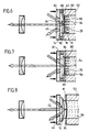
- the carrier 40 and the solid body 10 are connected by a holding layer, designated as a whole by 80, which is effective between the carrier surface 42 and the second flat side 14, the holding layer 80 not is only transparent for the laser radiation field 20 and possibly also the pump radiation field 32, but also has a refractive index n 80 which is selected such that a refractive index difference between a refractive index n 40 of the material of the carrier 40 and the refractive index n 80 of the holding layer 80 and a The difference in refractive index between the refractive index n 10 of the solid 10 and the refractive index n 80 of the holding layer 80 is in each case less than 10 -2 in order to obtain the smallest possible reflections on the holding layer 80.
- a third embodiment shown in Fig. 5, is for reduction reflections on the holding layer 80, preferably between the holding layer 80 and the carrier 40, an anti-reflective layer 82 is provided and an antireflection layer 84 between the holding layer 80 and the solid 10, both antireflection layers 82 and 84 optimally match the Allow material of the holding layer 80.
- Solid body 10 is not supported directly flat on the support surface 42, but in the second exemplary embodiment only indirectly via the holding layer 80 and in the third exemplary embodiment indirectly via the anti-reflective layers 82 and 84 and the intermediate holding layer 80.
- the second and third embodiments are with the first Embodiment identical, so that with regard to the other features fully reference to the comments on the first embodiment can be taken.
- the fourth exemplary embodiment the solid body 10 with its second flat side 14 only applied to the support surface 42, but not indirectly or directly through an effective agent between the solid 10 and the carrier 40 with this connected.
- the solid 10 experiences from the side of the pressurized Cooling medium 26 is pressurized in a direction 86 which leads to Carrier surface 42 points out and substantially perpendicular to the carrier surface 42 stands, so that the pressurized cooling medium 56 is also used is to create the second flat side 14 flat on the support surface 42 and thus to be supported on the carrier 40 and thus the solid due to the form-defined with the support surface 42 cooperating second flat side 14 and hold position-defined.
- the carrier 40 is not directly on the holder housing 52 held, but the carrier 40 is in turn held by a retaining ring 90 held and this is also over thermally insulating spacers 92 supported on the holder housing 52, so that due to the carrier 40 the thermal insulation from the holder housing 52 essentially no cooling of the solid 10 can take place.
- the fifth embodiment is based on the principle of the fourth embodiment, however, the cooling chamber 54 is covered by a membrane 94 Area of their opening 60 closed, and this membrane 94 now acts in turn onto the solid 10, in which case the coating 26, which represents the first reflector 24, not additionally with the cover layer 64 needs to be provided, but also provided with the cover layer 64 can be.
- the membrane 94 is made of a material that allows that the membrane 94 is flat on the solid 10, d. H. for example the coating 26, applies and the solid 10 flat in the direction of Carrier surface 42 is applied, so that in the same way as in context described with the fourth embodiment, by the carrier 40 with the Carrier surface 42 of the solid body held shape-defined and position-defined is.
- the advantage of the membrane 94 in the fifth exemplary embodiment is too see that this seals the cooling chamber 54 against leakage of the cooling medium 56 ensured in a simple manner and thus the cooling medium 56 act on the solid 10 with a correspondingly high pressure can.
- the solid 10 is merely by pressurization from the cooling medium 56, which on the Membrane 94 acts in contact with the convex support surface 42 of the support 40 held.
- the advantage of the fourth, fifth and sixth embodiment is thus to be seen in that the pressurized cooling medium 56 on the solid 10 essentially over its entire first flat side 12 with a acts constant pressure force in the direction of the support surface 42 and thus the Possibility exists, the solid body 10 with a substantially uniform To maintain compressive force on the support surface 42, either as in the first embodiment, the second flat side immediately can be supported on the support surface 42 or indirectly by optionally antireflection layers arranged between the carrier 40 and the solid body 10.
- a seventh embodiment shown in Fig. 9 those are Parts that are identical to those of the previous exemplary embodiments provided with the same reference numerals, so that with regard to the description the same with respect to the above exemplary embodiments can be taken.
- the solid body 10 covers the Opening 60 of the recess 62 receiving the cooling chamber 54 from and thus serves to seal the cooling chamber 54 in the area of the opening 60, so that the cooling medium 56 immediately the rear 70 of the cover layer 64th inflows to the heat in the context of the preceding Embodiments described to dissipate.
- the force with which the second flat side 14 is in the region of the Partial volume 22 on the support surface 42 in the area of the volume area 44 is present, less than the force with which the second flat side 14 in the outer Area 96 abuts the outer area 98 of the support surface 42.
- the eighth exemplary embodiment according to FIG. 10 is based on the basic principle of the seventh embodiment, although in the eighth embodiment the solid body 10 does not close the opening 60 and thus the cooling chamber 54 sealing with the fluid cooling medium 56 provided therein completes, but in addition to closing the cooling chamber 54 Membrane 94, already in connection with the fifth embodiment was explained, is used.
- the membrane 94 thus allows the pressure of the cooling medium to be added 56 acts on the solid body 10 via the membrane 94, around this to bear against the support surface 42.
- a ninth embodiment shown in Fig. 11 the same thing happens Principle of use as in the seventh exemplary embodiment according to FIG. 9, however with the difference that the solid body 10 has a curved basic shape with a convex second flat side 14, so that when pressing the Solid body 10 by acting on it in its outer region 96 the solid body 10 itself essentially over the entire second flat side 14 rests on the support surface 42 with essentially the same force, since the Solid body 10 due to its leading to the convex second flat side 14 curved basic shape when pressed against the flat support surface 42 and thus the required deformation of the basic shape of the solid 10 in such a way that the second flat side 14 is pressed over the entire surface of the flat support surface 42, internal tensions generated which for a substantially uniform contact pressure of the second Provide flat side 14 on the support surface 42.
Landscapes
- Physics & Mathematics (AREA)
- Electromagnetism (AREA)
- Chemical & Material Sciences (AREA)
- Crystallography & Structural Chemistry (AREA)
- Engineering & Computer Science (AREA)
- Plasma & Fusion (AREA)
- Optics & Photonics (AREA)
- Lasers (AREA)
- Amplifiers (AREA)
Abstract
Description
- Fig. 1
- einen Längsschnitt durch ein erstes Ausführungsbeispiel eines erfindungsgemäßen Laserverstärkersystems;
- Fig. 2
- eine vergrößerte ausschnittsweise Darstellung des Bereichs A in Fig. 1;
- Fig. 3
- eine nochmals vergrößerte Darstellung des Schnitts ähnlich Fig. 2 durch einen Festkörper des erfindungsgemäßen Laserverstärkersystems mit Darstellung von Isothermen;
- Fig. 4
- einen Schnitt ähnlich Fig. 2 durch ein zweites Ausführungsbeispiel;
- Fig. 5
- einen Schnitt ähnlich Fig. 2 durch ein drittes Ausführungsbeispiel;
- Fig. 6
- einen Schnitt ähnlich Fig. 1 durch ein viertes Ausführungsbeispiel;
- Fig. 7
- einen Schnitt ähnlich Fig. 1 durch ein fünftes Ausführungsbeispiel;
- Fig. 8
- einen Schnitt ähnlich Fig. 1 durch ein sechstes Ausführungsbeispiel;
- Fig. 9
- einen Schnitt ähnlich Fig. 1 durch ein siebtes Ausführungsbeispiel;
- Fig. 10
- einen Schnitt ähnlich Fig. 1 durch ein achtes Ausführungsbeispiel und
- Fig. 11
- einen Schnitt ähnlich Fig. 1 durch ein neuntes Ausführungsbeispiel.
Claims (40)
- Laserverstärkersystem umfassend
einen einander gegenüberliegende Flachseiten (12, 14) aufweisenden, plattenförmig ausgebildeten Festkörper (10), der ein laseraktives Material umfaßt,
ein den Festkörper (10) durchsetzendes Laserstrahlungsfeld (20),
ein das laseraktive Material pumpendes Pumpstrahlungsfeld (32),
eine Kühleinrichtung (50), welche aus dem Festkörper (10) über eine erste Flachseite (12) Wärme mittels eines in dieser strömenden fluiden Kühlmediums (56) aufnimmt,
und einen auf der ersten Flachseite (12) angeordneten Reflektor (24) für das Laserstrahlungsfeld (20),
dadurch gekennzeichnet, daß ein von dem Laserstrahlungsfeld (20) durchsetzter und für dieses transparenter formstabiler Träger (40) für den Festkörper (10) vorgesehen ist,
daß der Festkörper (10) mit seiner zweiten Flachseite (14) auf einer Trägerfläche (42) des formstabilen Trägers (40) flächig abgestützt ist und im wesentlichen nur über die mit der zweiten Flachseite (14) zusammenwirkende Trägerfläche (42) formdefiniert und positionsdefiniert angeordnet ist. - Laserverstärkersystem nach Anspruch 1, dadurch gekennzeichnet, daß die erste Flachseite (12) im vom Laserstrahlungsfeld (20) durchsetzten Bereich frei von durch eine in sich mechanisch starre Fläche vorgegebenen Zwangskräften ist.
- Laserverstärkersystem nach Anspruch 1 oder 2, dadurch gekennzeichnet, daß der Festkörper (10) an dem Träger (40) fixiert ist.
- Laserverstärkersystem nach Anspruch 3, dadurch gekennzeichnet, daß der Festkörper (10) an dem Träger (40) durch eine zwischen der Trägerfläche (42) und der zweiten Flachseite (14) wirksame Verbindung fixiert ist.
- Laserverstärkersystem nach Anspruch 4, dadurch gekennzeichnet, daß die Verbindung zwischen der Trägerfläche (42) und der zweiten Flachseite (14) durch Bonden von Träger (40) und Festkörper (10) entstanden ist.
- Laserverstärkersystem nach Anspruch 4, dadurch gekennzeichnet, daß die Verbindung zwischen der Trägerfläche (42) und der zweiten Flachseite (14) durch eine Halteschicht (80) erfolgt.
- Laserverstärkersystem nach Anspruch 6, dadurch gekennzeichnet, daß die Halteschicht (80) hinsichtlich ihres Brechungsindex (n80) an den Brechungsindex (n10) des Festkörpers (10) angepaßt ist.
- Laserverstärkersystem nach Anspruch 7, dadurch gekennzeichnet, daß zwischen der Halteschicht (80) und dem Träger (40) und/oder der Halteschicht (80) und dem Festkörper (10) jeweils ein Brechungsindexunterschied (n80 - n40, n80 - n10) von weniger als 10-2 besteht.
- Laserverstärkersystem nach einem der Ansprüche 6 bis 8, dadurch gekennzeichnet, daß zwischen der Halteschicht (80) und dem Träger (40) eine Antireflexschicht (82) vorgesehen ist.
- Laserverstärkersystem nach einem der Ansprüche 6 bis 9, dadurch gekennzeichnet, daß zwischen der Halteschicht (80) und dem Festkörper (10) eine Antireflexschicht (84) vorgesehen ist.
- Laserverstärkersystem nach einem der Ansprüche 1 bis 3, dadurch gekennzeichnet, daß der Festkörper (10) und der Träger (40) im Bereich der Trägerfläche (42) und der zweiten Flachseite (14) kraftschlüssig durch Druckbeaufschlagung des Festkörpers in Richtung des Trägers fixiert sind.
- Laserverstärkersystem nach Anspruch 11, dadurch gekennzeichnet, daß der Festkörper (10) durch das Kühlmedium (56) in Richtung (86) des Trägers (42) kraftbeaufschlagt ist.
- Laserverstärkersystem nach Anspruch 11 oder 12, dadurch gekennzeichnet, daß der Festkörper (10) in Teilbereichen (96) in Richtung des Trägers (40) kraftbeaufschlagt ist.
- Laserverstärkersystem nach einem der Ansprüche 11 bis 13, dadurch gekennzeichnet, daß der Festkörper (10) in einem außerhalb des Laserstrahlungsfeldes (20) liegenden äußeren Bereich (96) in Richtung des Trägers (40) kraftbeaufschlagt ist.
- Laserverstärkersystem nach einem der Ansprüche 11 bis 14, dadurch gekennzeichnet, daß der Festkörper (10) mit dem an das vom Laserstrahlungsfeld (20) durchsetzte Teilvolumen (22) angrenzenden Bereich der zweiten Flachseite (14) in jedem Punkt mit im wesentlichen derselben Kraft auf den Träger (40) wirkt.
- Laserverstärkersystem nach einem der Ansprüche 11 bis 15, dadurch gekennzeichnet, daß der mit der zweiten Flachseite (14) an der Trägerfläche (42) anliegende Festkörper (10) zumindest mit dem an den vom Laserstrahlungsfeld (20) durchsetzten Teilvolumen (22) angrenzenden Bereich der zweiten Trägerfläche (42) aufgrund innerer Vorspannung auf den Träger (40) wirkt.
- Laserverstärkersystem nach Anspruch 16, dadurch gekennzeichnet, daß die zweite Flachseite (14) vor dem Anlegen derselben an der Trägerfläche (42) eine konvexe Wölbung aufweist.
- Laserverstärkersystem nach einem der voranstehenden Ansprüche, dadurch gekennzeichnet, daß in den von dem Laserstrahlungsfeld (20) durchsetzten Bereichen der ersten und zweiten Flachseite (12, 14) die Temperatur an der zweiten Flachseite (14) höher ist als an der ersten Flachseite (12).
- Laserverstärkersystem nach einem der voranstehenden Ansprüche, dadurch gekennzeichnet, daß der Festkörper in dem vom Laserstrahlungsfeld (20) durchsetzten Volumenbereich (22) einen im wesentlichen ausschließlich quer zu den Flachseiten (12, 14) verlaufenden Temperaturgradient aufweist.
- Laserverstärkersystem nach einem der voranstehenden Ansprüche, dadurch gekennzeichnet, daß der Festkörper (10) in dem vom Laserstrahlungsfeld (20) durchsetzten Volumenbereich (22) in Richtung einer Flächenausdehnung der Flachseiten (12, 14) im wesentlichen temperaturgradientenfrei ist.
- Laserverstärkersystem nach einem der voranstehenden Ansprüche, dadurch gekennzeichnet, daß in dem Festkörper (10) in einer sich quer zu den Flachseiten (12, 14) erstreckenden und von der zweiten Flachseite (14) zur ersten Flachseite (12) verlaufenden Richtung ein insgesamt negativer Temperaturgradient auftritt.
- Laserverstärkersystem nach einem der voranstehenden Ansprüche, dadurch gekennzeichnet, daß die Ableitung der Wärme aus dem Festkörper (10) über ein mindestens eine auf den Festkörper (10) aufgetragene Schicht (26) umfassendes Schichtsystem (26, 64, 94) erfolgt.
- Laserverstärkersystem nach Anspruch 22, dadurch gekennzeichnet, daß das Schichtsystem (26, 64, 94) auf einer der ersten Flachseite (12) gegenüberliegenden Seite (70, 94) unmittelbar vom fluiden Kühlmedium (56) beaufschlagt ist.
- Laserverstärkersystem nach Anspruch 22 oder 23, dadurch gekennzeichnet, daß die Abfuhr von Wärme aus dem Festkörper (10) zu dem fluiden Kühlmedium ausschließlich über Schichten (26, 64, 94) aus formflexiblen Materialien erfolgt.
- Laserverstärkersystem nach einem der Ansprüche 22 bis 24, dadurch gekennzeichnet, daß die Schichten (26, 64, 94), über welche die Abfuhr von Wärme aus dem Festkörper (10) zum fluiden Kühlmedium (56) erfolgt, insgesamt einen Wärmewiderstand von höchstens 8 K mm 2 / W aufweisen.
- Laserverstärkersystem nach einem der Ansprüche 22 bis 25, dadurch gekennzeichnet, daß die Wärmeabfuhr durch die Kühleinrichtung (50) über eine von einer Reflektorschicht (26) getragene Deckschicht (64) erfolgt, welche auf einer dem Festkörper (10) abgewandten Seite (70) von dem fluiden Kühlmedium (56) beaufschlagt ist.
- Laserverstärkersystem nach Anspruch 26, dadurch gekennzeichnet, daß die Deckschicht (64) eine Schutzschicht für die Reflektorschicht (26) gegen Einwirkung des Kühlmediums (56) darstellt.
- Laserverstärkersystem nach Anspruch 26 oder 27, dadurch gekennzeichnet, daß über die Deckschicht (64) keine formdefinierende Einwirkung auf den Festkörper (10) erfolgt.
- Laserverstärkersystem nach Anspruch 26 oder 28, dadurch gekennzeichnet, daß die Deckschicht (64) als flexible Schicht ausgebildet ist.
- Laserverstärkersystem nach einem der Ansprüche 26 bis 29, dadurch gekennzeichnet, daß die Deckschicht (64) als sich an die Form des Festkörpers (10) formadaptierende Schicht ausgebildet ist.
- Laserverstärkersystem nach einem der Ansprüche 22 bis 26, dadurch gekennzeichnet, daß das Schichtsystem (26, 64, 94) eine Membran (94) umfaßt, welche auf ihrer dem Festkörper (10) abgewandten Seite von dem fluiden Kühlmedium (56) beaufschlagt ist.
- Laserverstärkersystem nach einem der voranstehenden Ansprüche, dadurch gekennzeichnet, daß der Festkörper (10) mit dem Schichtsystem (26, 64, 94) eine das Kühlmedium (56) führende Kühlkammer (54) begrenzt.
- Laserverstärkersystem nach Anspruch 32, dadurch gekennzeichnet, daß die Kühlkammer (54) für das Kühlmedium (56) in einem Haltergehäuse (52) angeordnet ist.
- Laserverstärkersystem nach Anspruch 33, dadurch gekennzeichnet, daß der Träger (40) mit dem Festkörper (10) eine Öffnung (60) im Haltergehäuse (52) verschließt.
- Laserverstärkersystem nach einem der voranstehenden Ansprüche, dadurch gekennzeichnet, daß der Träger (40) aus einem Material mit einer Wärmeleitfähigkeit kleiner 2 W / m · K ausgebildet ist.
- Laserverstärkersystem nach einem der voranstehenden Ansprüche, dadurch gekennzeichnet, daß der Träger (40) aus einem athermalen optischen Material gebildet ist.
- Laserverstärkersystem nach einem der voranstehenden Ansprüche, dadurch gekennzeichnet, daß der Träger (40) gegenüber der Kühleinrichtung (50) thermisch isoliert ist.
- Laserverstärkersystem nach einem der voranstehenden Ansprüche, dadurch gekennzeichnet, daß der Träger (40) und der Festkörper (10) ähnliche kristallgitterbildende Materialien aufweisen.
- Laserverstärkersystem nach einem der voranstehenden Ansprüche, dadurch gekennzeichnet, daß die Flachseiten (12, 14) des Festkörpers (10) planparallel poliert sind.
- Laserverstärkersystem nach einem der Ansprüche 1 bis 38, dadurch gekennzeichnet, daß der Träger (40) und der Festkörper (10) im Bereich der zweiten Flachseite (14) und der Trägerfläche (42) miteinander verbunden sind und die erste Flachseite (12) und eine der Trägerfläche (42) gegenüberliegende Frontfläche des Trägers (40) planparallel zueinander poliert sind.
Applications Claiming Priority (2)
| Application Number | Priority Date | Filing Date | Title |
|---|---|---|---|
| DE10061424A DE10061424A1 (de) | 2000-12-09 | 2000-12-09 | Laserverstärkersystem |
| DE10061424 | 2000-12-09 |
Publications (3)
| Publication Number | Publication Date |
|---|---|
| EP1213801A2 true EP1213801A2 (de) | 2002-06-12 |
| EP1213801A3 EP1213801A3 (de) | 2004-10-20 |
| EP1213801B1 EP1213801B1 (de) | 2007-01-03 |
Family
ID=7666518
Family Applications (1)
| Application Number | Title | Priority Date | Filing Date |
|---|---|---|---|
| EP01129075A Expired - Lifetime EP1213801B1 (de) | 2000-12-09 | 2001-12-07 | Laserverstärkersystem |
Country Status (4)
| Country | Link |
|---|---|
| US (1) | US6747789B2 (de) |
| EP (1) | EP1213801B1 (de) |
| AT (1) | ATE350788T1 (de) |
| DE (2) | DE10061424A1 (de) |
Cited By (2)
| Publication number | Priority date | Publication date | Assignee | Title |
|---|---|---|---|---|
| DE102015216655A1 (de) | 2015-09-01 | 2017-03-02 | Trumpf Laser Gmbh | Plattenförmiger laseraktiver Festkörper mit einem kristallinen hochreflektierenden Spiegel und Verfahren zu seiner Herstellung |
| DE102016205638A1 (de) | 2016-04-05 | 2017-10-05 | Trumpf Laser Gmbh | Prallkühlvorrichtung für eine Laserscheibe und zugehöriges Laserscheibenmodul |
Families Citing this family (9)
| Publication number | Priority date | Publication date | Assignee | Title |
|---|---|---|---|---|
| WO2003047052A2 (en) * | 2001-11-21 | 2003-06-05 | General Atomics | Laser containing a distributed gain medium |
| DE10219004A1 (de) * | 2002-04-27 | 2003-11-13 | Rofin Sinar Laser Gmbh | Laserstrahlquelle mit einem eine dünne Kristallscheibe als laseraktives Medium enthaltenden Laserelement |
| DE10339980B4 (de) * | 2003-08-29 | 2011-01-05 | Osram Opto Semiconductors Gmbh | Halbleiterlaser mit reduzierter Verlustwärme |
| WO2006020925A2 (en) * | 2004-08-12 | 2006-02-23 | Spectra Physics, Inc. | High thermal-conductivity materials for a cooled laser gain assembly |
| CN100452571C (zh) * | 2006-12-13 | 2009-01-14 | 中国科学院上海光学精密机械研究所 | 倍频晶体温度梯度补偿法控温装置 |
| DE102010003227A1 (de) | 2010-03-24 | 2011-09-29 | Universität Stuttgart Institut für Strahlwerkzeuge | Lasersystem |
| DE102015114263A1 (de) | 2015-08-27 | 2017-03-02 | Trumpf Laser Gmbh | Verspannungsoptimiertes Laserscheibenträgersystem |
| FR3074972B1 (fr) * | 2017-12-07 | 2020-10-16 | Commissariat Energie Atomique | Element d'un laser a disque comportant le milieu amplificateur et des moyens ameliores de refroidissement. |
| JP7341673B2 (ja) * | 2019-02-27 | 2023-09-11 | 三菱重工業株式会社 | レーザ装置 |
Family Cites Families (8)
| Publication number | Priority date | Publication date | Assignee | Title |
|---|---|---|---|---|
| US4245195A (en) * | 1979-07-16 | 1981-01-13 | Gte Products Corporation | Laser optical resonator assembly |
| EP0166028A3 (de) * | 1984-06-25 | 1987-04-22 | Siemens Aktiengesellschaft | Justiereinrichtung für einen Reflektorspiegel eines Laserresonators |
| US4815094A (en) * | 1987-05-22 | 1989-03-21 | California Laboratories, Inc. | Multiply folded laser systems |
| DE59410441D1 (de) * | 1993-07-02 | 2006-10-26 | Deutsch Zentr Luft & Raumfahrt | Laserverstärkersystem |
| US5796766A (en) * | 1994-08-23 | 1998-08-18 | Laser Power Corporation | Optically transparent heat sink for longitudinally cooling an element in a laser |
| US6101201A (en) * | 1996-10-21 | 2000-08-08 | Melles Griot, Inc. | Solid state laser with longitudinal cooling |
| US6347109B1 (en) * | 1999-01-25 | 2002-02-12 | The Regents Of The University Of California | High average power scaleable thin-disk laser |
| US6385220B1 (en) * | 1999-04-21 | 2002-05-07 | Gsi Lumonics Inc. | Laser clamping assembly and method |
-
2000
- 2000-12-09 DE DE10061424A patent/DE10061424A1/de not_active Ceased
-
2001
- 2001-12-06 US US10/007,651 patent/US6747789B2/en not_active Expired - Lifetime
- 2001-12-07 EP EP01129075A patent/EP1213801B1/de not_active Expired - Lifetime
- 2001-12-07 DE DE50111785T patent/DE50111785D1/de not_active Expired - Lifetime
- 2001-12-07 AT AT01129075T patent/ATE350788T1/de not_active IP Right Cessation
Cited By (7)
| Publication number | Priority date | Publication date | Assignee | Title |
|---|---|---|---|---|
| DE102015216655A1 (de) | 2015-09-01 | 2017-03-02 | Trumpf Laser Gmbh | Plattenförmiger laseraktiver Festkörper mit einem kristallinen hochreflektierenden Spiegel und Verfahren zu seiner Herstellung |
| WO2017036809A1 (de) | 2015-09-01 | 2017-03-09 | Trumpf Laser Gmbh | Plattenförmiger laseraktiver festkörper mit einem kristallinen hochreflektierenden spiegel und verfahren zu seiner herstellung |
| DE102016205638A1 (de) | 2016-04-05 | 2017-10-05 | Trumpf Laser Gmbh | Prallkühlvorrichtung für eine Laserscheibe und zugehöriges Laserscheibenmodul |
| WO2017174369A1 (de) | 2016-04-05 | 2017-10-12 | Trumpf Laser Gmbh | Prallkühlvorrichtung für eine laserscheibe und zugehöriges laserscheibenmodul |
| DE102016205638B4 (de) | 2016-04-05 | 2019-05-09 | Trumpf Laser Gmbh | Prallkühlvorrichtung für eine Laserscheibe und zugehöriges Laserscheibenmodul |
| US10727639B2 (en) | 2016-04-05 | 2020-07-28 | Trumpf Laser Gmbh | Impingement cooling device for a laser disk and associated laser disk module |
| US11362475B2 (en) | 2016-04-05 | 2022-06-14 | Trumpf Laser Gmbh | Impingement cooling device for a laser disk and associated laser disk module |
Also Published As
| Publication number | Publication date |
|---|---|
| US20020126373A1 (en) | 2002-09-12 |
| EP1213801B1 (de) | 2007-01-03 |
| ATE350788T1 (de) | 2007-01-15 |
| EP1213801A3 (de) | 2004-10-20 |
| US6747789B2 (en) | 2004-06-08 |
| DE50111785D1 (de) | 2007-02-15 |
| DE10061424A1 (de) | 2002-06-13 |
Similar Documents
| Publication | Publication Date | Title |
|---|---|---|
| DE4433888C2 (de) | Festkörperlaser mit Kühleinrichtung | |
| EP1213801A2 (de) | Laserverstärkersystem | |
| DE102017125099B4 (de) | Laserkomponente und Verfahren zu ihrer Herstellung | |
| DE602004005941T2 (de) | Anordnung und Verfahren zum Richten eines Laserstrahls auf Werkstücke | |
| EP1500173B1 (de) | Laserstrahlquelle mit einem eine dünne kristallscheibe als laseraktives medium enthaltenden laserelement | |
| DE60001565T2 (de) | Laser-klemmvorrichtung und herstellungsverfahren | |
| EP1178579B1 (de) | Laserverstärkeranordnung | |
| AT405776B (de) | Kühlvorrichtung für einen laserkristall | |
| DE69804084T2 (de) | Thermisch verbesserter pumphohlraum mit integriertem konzetrator für bandleiterlaser | |
| DE102017112620A1 (de) | Lasersystem und Herstellungsverfahren | |
| EP1205013B1 (de) | Festkörperlaserkühlung | |
| DE102023103583A1 (de) | Optischer Plattenverstärker und Verfahren zum Betrieb | |
| DE102008008078A1 (de) | Festkörper-Laser | |
| WO2024170625A1 (de) | Optischer plattenverstärker und verfahren zum betrieb | |
| DE69003958T2 (de) | Laser mit Halterungsvorrichtung des aktiven Materials und Halterungsvorrichtung für den Laseraufbau. | |
| DE102012112554A1 (de) | Kühlanordnung für laseraktive Festkörpermaterialien, Laseranordnung und Verfahren zur Kühlung eines laseraktiven Festkörpermaterials | |
| DE102008061309A1 (de) | Diodenlaserbauelement | |
| DE212012000230U1 (de) | Befestigung für ein optisches Element eines Lasers | |
| EP0678705B1 (de) | Bestrahlungsvorrichtung | |
| DE112008002013T5 (de) | Kompensation thermischer Verzerrung für Laserspiegel | |
| DE3151228C2 (de) | Optischer Resonator für einen Laser | |
| DE10328305A1 (de) | Verstärkeranordnung | |
| DE102016202028B4 (de) | Halter für einen Wellenlängenumwandlungskristall und optisches System mit einem solchen Halter | |
| DE102015111375B4 (de) | Anordnung zur Abstützung eines optischen Bauteils | |
| DE102013009509A1 (de) | Laserverstärkersystem, umfassend eine Festkörperscheibe mit thermischer Homogenisierungsschicht zur Wärmespreizung |
Legal Events
| Date | Code | Title | Description |
|---|---|---|---|
| PUAI | Public reference made under article 153(3) epc to a published international application that has entered the european phase |
Free format text: ORIGINAL CODE: 0009012 |
|
| AK | Designated contracting states |
Kind code of ref document: A2 Designated state(s): AT BE CH CY DE DK ES FI FR GB GR IE IT LI LU MC NL PT SE TR |
|
| AX | Request for extension of the european patent |
Free format text: AL;LT;LV;MK;RO;SI |
|
| PUAL | Search report despatched |
Free format text: ORIGINAL CODE: 0009013 |
|
| AK | Designated contracting states |
Kind code of ref document: A3 Designated state(s): AT BE CH CY DE DK ES FI FR GB GR IE IT LI LU MC NL PT SE TR |
|
| AX | Request for extension of the european patent |
Extension state: AL LT LV MK RO SI |
|
| 17P | Request for examination filed |
Effective date: 20041216 |
|
| RAP1 | Party data changed (applicant data changed or rights of an application transferred) |
Owner name: TRUMPF LASER GMBH + CO. KG |
|
| 17Q | First examination report despatched |
Effective date: 20050513 |
|
| AKX | Designation fees paid |
Designated state(s): AT BE CH CY DE DK ES FI FR GB GR IE IT LI LU MC NL PT SE TR |
|
| GRAP | Despatch of communication of intention to grant a patent |
Free format text: ORIGINAL CODE: EPIDOSNIGR1 |
|
| GRAS | Grant fee paid |
Free format text: ORIGINAL CODE: EPIDOSNIGR3 |
|
| GRAA | (expected) grant |
Free format text: ORIGINAL CODE: 0009210 |
|
| AK | Designated contracting states |
Kind code of ref document: B1 Designated state(s): AT BE CH CY DE DK ES FI FR GB GR IE IT LI LU MC NL PT SE TR |
|
| PG25 | Lapsed in a contracting state [announced via postgrant information from national office to epo] |
Ref country code: DK Free format text: LAPSE BECAUSE OF FAILURE TO SUBMIT A TRANSLATION OF THE DESCRIPTION OR TO PAY THE FEE WITHIN THE PRESCRIBED TIME-LIMIT Effective date: 20070103 Ref country code: NL Free format text: LAPSE BECAUSE OF FAILURE TO SUBMIT A TRANSLATION OF THE DESCRIPTION OR TO PAY THE FEE WITHIN THE PRESCRIBED TIME-LIMIT Effective date: 20070103 Ref country code: IE Free format text: LAPSE BECAUSE OF FAILURE TO SUBMIT A TRANSLATION OF THE DESCRIPTION OR TO PAY THE FEE WITHIN THE PRESCRIBED TIME-LIMIT Effective date: 20070103 Ref country code: FI Free format text: LAPSE BECAUSE OF FAILURE TO SUBMIT A TRANSLATION OF THE DESCRIPTION OR TO PAY THE FEE WITHIN THE PRESCRIBED TIME-LIMIT Effective date: 20070103 |
|
| REG | Reference to a national code |
Ref country code: GB Ref legal event code: FG4D Free format text: NOT ENGLISH |
|
| REF | Corresponds to: |
Ref document number: 50111785 Country of ref document: DE Date of ref document: 20070215 Kind code of ref document: P |
|
| REG | Reference to a national code |
Ref country code: IE Ref legal event code: FG4D Free format text: LANGUAGE OF EP DOCUMENT: GERMAN |
|
| REG | Reference to a national code |
Ref country code: CH Ref legal event code: NV Representative=s name: KIRKER & CIE SA |
|
| PG25 | Lapsed in a contracting state [announced via postgrant information from national office to epo] |
Ref country code: SE Free format text: LAPSE BECAUSE OF FAILURE TO SUBMIT A TRANSLATION OF THE DESCRIPTION OR TO PAY THE FEE WITHIN THE PRESCRIBED TIME-LIMIT Effective date: 20070403 |
|
| PG25 | Lapsed in a contracting state [announced via postgrant information from national office to epo] |
Ref country code: ES Free format text: LAPSE BECAUSE OF FAILURE TO SUBMIT A TRANSLATION OF THE DESCRIPTION OR TO PAY THE FEE WITHIN THE PRESCRIBED TIME-LIMIT Effective date: 20070414 |
|
| GBT | Gb: translation of ep patent filed (gb section 77(6)(a)/1977) |
Effective date: 20070404 |
|
| PG25 | Lapsed in a contracting state [announced via postgrant information from national office to epo] |
Ref country code: PT Free format text: LAPSE BECAUSE OF FAILURE TO SUBMIT A TRANSLATION OF THE DESCRIPTION OR TO PAY THE FEE WITHIN THE PRESCRIBED TIME-LIMIT Effective date: 20070604 |
|
| ET | Fr: translation filed | ||
| NLV1 | Nl: lapsed or annulled due to failure to fulfill the requirements of art. 29p and 29m of the patents act | ||
| REG | Reference to a national code |
Ref country code: IE Ref legal event code: FD4D |
|
| PLBI | Opposition filed |
Free format text: ORIGINAL CODE: 0009260 |
|
| 26 | Opposition filed |
Opponent name: ROFIN-SINAR LASER GMBH Effective date: 20071002 |
|
| PLAX | Notice of opposition and request to file observation + time limit sent |
Free format text: ORIGINAL CODE: EPIDOSNOBS2 |
|
| PLAF | Information modified related to communication of a notice of opposition and request to file observations + time limit |
Free format text: ORIGINAL CODE: EPIDOSCOBS2 |
|
| PG25 | Lapsed in a contracting state [announced via postgrant information from national office to epo] |
Ref country code: GR Free format text: LAPSE BECAUSE OF FAILURE TO SUBMIT A TRANSLATION OF THE DESCRIPTION OR TO PAY THE FEE WITHIN THE PRESCRIBED TIME-LIMIT Effective date: 20070404 |
|
| PLAF | Information modified related to communication of a notice of opposition and request to file observations + time limit |
Free format text: ORIGINAL CODE: EPIDOSCOBS2 |
|
| BERE | Be: lapsed |
Owner name: TRUMPF LASER G.M.B.H. + CO. KG Effective date: 20071231 |
|
| PLAF | Information modified related to communication of a notice of opposition and request to file observations + time limit |
Free format text: ORIGINAL CODE: EPIDOSCOBS2 |
|
| PG25 | Lapsed in a contracting state [announced via postgrant information from national office to epo] |
Ref country code: MC Free format text: LAPSE BECAUSE OF NON-PAYMENT OF DUE FEES Effective date: 20071231 |
|
| PLBP | Opposition withdrawn |
Free format text: ORIGINAL CODE: 0009264 |
|
| PLBB | Reply of patent proprietor to notice(s) of opposition received |
Free format text: ORIGINAL CODE: EPIDOSNOBS3 |
|
| PG25 | Lapsed in a contracting state [announced via postgrant information from national office to epo] |
Ref country code: BE Free format text: LAPSE BECAUSE OF NON-PAYMENT OF DUE FEES Effective date: 20071231 |
|
| PGFP | Annual fee paid to national office [announced via postgrant information from national office to epo] |
Ref country code: AT Payment date: 20081218 Year of fee payment: 8 |
|
| PGFP | Annual fee paid to national office [announced via postgrant information from national office to epo] |
Ref country code: IT Payment date: 20081223 Year of fee payment: 8 |
|
| PLBD | Termination of opposition procedure: decision despatched |
Free format text: ORIGINAL CODE: EPIDOSNOPC1 |
|
| PG25 | Lapsed in a contracting state [announced via postgrant information from national office to epo] |
Ref country code: CY Free format text: LAPSE BECAUSE OF FAILURE TO SUBMIT A TRANSLATION OF THE DESCRIPTION OR TO PAY THE FEE WITHIN THE PRESCRIBED TIME-LIMIT Effective date: 20070103 |
|
| PG25 | Lapsed in a contracting state [announced via postgrant information from national office to epo] |
Ref country code: LU Free format text: LAPSE BECAUSE OF NON-PAYMENT OF DUE FEES Effective date: 20071207 |
|
| PG25 | Lapsed in a contracting state [announced via postgrant information from national office to epo] |
Ref country code: TR Free format text: LAPSE BECAUSE OF FAILURE TO SUBMIT A TRANSLATION OF THE DESCRIPTION OR TO PAY THE FEE WITHIN THE PRESCRIBED TIME-LIMIT Effective date: 20070103 |
|
| PLBM | Termination of opposition procedure: date of legal effect published |
Free format text: ORIGINAL CODE: 0009276 |
|
| STAA | Information on the status of an ep patent application or granted ep patent |
Free format text: STATUS: OPPOSITION PROCEDURE CLOSED |
|
| 27C | Opposition proceedings terminated |
Effective date: 20090814 |
|
| PG25 | Lapsed in a contracting state [announced via postgrant information from national office to epo] |
Ref country code: AT Free format text: LAPSE BECAUSE OF NON-PAYMENT OF DUE FEES Effective date: 20091207 |
|
| PG25 | Lapsed in a contracting state [announced via postgrant information from national office to epo] |
Ref country code: IT Free format text: LAPSE BECAUSE OF NON-PAYMENT OF DUE FEES Effective date: 20091207 |
|
| REG | Reference to a national code |
Ref country code: DE Ref legal event code: R082 Ref document number: 50111785 Country of ref document: DE Representative=s name: HOEGER, STELLRECHT & PARTNER PATENTANWAELTE MB, DE |
|
| REG | Reference to a national code |
Ref country code: FR Ref legal event code: PLFP Year of fee payment: 15 |
|
| REG | Reference to a national code |
Ref country code: FR Ref legal event code: PLFP Year of fee payment: 16 |
|
| REG | Reference to a national code |
Ref country code: FR Ref legal event code: PLFP Year of fee payment: 17 |
|
| REG | Reference to a national code |
Ref country code: DE Ref legal event code: R082 Ref document number: 50111785 Country of ref document: DE Representative=s name: HOEGER, STELLRECHT & PARTNER PATENTANWAELTE MB, DE |
|
| PGFP | Annual fee paid to national office [announced via postgrant information from national office to epo] |
Ref country code: DE Payment date: 20191210 Year of fee payment: 19 |
|
| PGFP | Annual fee paid to national office [announced via postgrant information from national office to epo] |
Ref country code: FR Payment date: 20191219 Year of fee payment: 19 |
|
| PGFP | Annual fee paid to national office [announced via postgrant information from national office to epo] |
Ref country code: CH Payment date: 20191219 Year of fee payment: 19 |
|
| PGFP | Annual fee paid to national office [announced via postgrant information from national office to epo] |
Ref country code: GB Payment date: 20191220 Year of fee payment: 19 |
|
| REG | Reference to a national code |
Ref country code: DE Ref legal event code: R119 Ref document number: 50111785 Country of ref document: DE |
|
| REG | Reference to a national code |
Ref country code: CH Ref legal event code: PL |
|
| GBPC | Gb: european patent ceased through non-payment of renewal fee |
Effective date: 20201207 |
|
| PG25 | Lapsed in a contracting state [announced via postgrant information from national office to epo] |
Ref country code: FR Free format text: LAPSE BECAUSE OF NON-PAYMENT OF DUE FEES Effective date: 20201231 |
|
| PG25 | Lapsed in a contracting state [announced via postgrant information from national office to epo] |
Ref country code: LI Free format text: LAPSE BECAUSE OF NON-PAYMENT OF DUE FEES Effective date: 20201231 Ref country code: DE Free format text: LAPSE BECAUSE OF NON-PAYMENT OF DUE FEES Effective date: 20210701 Ref country code: GB Free format text: LAPSE BECAUSE OF NON-PAYMENT OF DUE FEES Effective date: 20201207 Ref country code: CH Free format text: LAPSE BECAUSE OF NON-PAYMENT OF DUE FEES Effective date: 20201231 |