EP1214006B1 - Polyaxiale knochenschraubenanordnung - Google Patents
Polyaxiale knochenschraubenanordnung Download PDFInfo
- Publication number
- EP1214006B1 EP1214006B1 EP00971073A EP00971073A EP1214006B1 EP 1214006 B1 EP1214006 B1 EP 1214006B1 EP 00971073 A EP00971073 A EP 00971073A EP 00971073 A EP00971073 A EP 00971073A EP 1214006 B1 EP1214006 B1 EP 1214006B1
- Authority
- EP
- European Patent Office
- Prior art keywords
- assembly
- head
- bone
- groove
- crown
- Prior art date
- Legal status (The legal status is an assumption and is not a legal conclusion. Google has not performed a legal analysis and makes no representation as to the accuracy of the status listed.)
- Expired - Lifetime
Links
- 210000000988 bone and bone Anatomy 0.000 title claims abstract description 129
- 230000006835 compression Effects 0.000 claims abstract description 12
- 238000007906 compression Methods 0.000 claims abstract description 12
- 238000013459 approach Methods 0.000 description 6
- 239000000463 material Substances 0.000 description 5
- 239000007943 implant Substances 0.000 description 4
- 230000000399 orthopedic effect Effects 0.000 description 4
- 238000000034 method Methods 0.000 description 3
- 238000001356 surgical procedure Methods 0.000 description 3
- 238000010276 construction Methods 0.000 description 2
- 238000013461 design Methods 0.000 description 2
- 238000003780 insertion Methods 0.000 description 2
- 230000037431 insertion Effects 0.000 description 2
- 210000004705 lumbosacral region Anatomy 0.000 description 2
- 238000007788 roughening Methods 0.000 description 2
- 230000000087 stabilizing effect Effects 0.000 description 2
- RTAQQCXQSZGOHL-UHFFFAOYSA-N Titanium Chemical compound [Ti] RTAQQCXQSZGOHL-UHFFFAOYSA-N 0.000 description 1
- 230000004075 alteration Effects 0.000 description 1
- 238000004873 anchoring Methods 0.000 description 1
- 238000005452 bending Methods 0.000 description 1
- 230000008901 benefit Effects 0.000 description 1
- 239000000560 biocompatible material Substances 0.000 description 1
- 230000001419 dependent effect Effects 0.000 description 1
- 238000005553 drilling Methods 0.000 description 1
- 238000005516 engineering process Methods 0.000 description 1
- 238000007373 indentation Methods 0.000 description 1
- 208000014674 injury Diseases 0.000 description 1
- 230000001045 lordotic effect Effects 0.000 description 1
- 230000036244 malformation Effects 0.000 description 1
- 230000007246 mechanism Effects 0.000 description 1
- 238000012986 modification Methods 0.000 description 1
- 230000004048 modification Effects 0.000 description 1
- 230000007170 pathology Effects 0.000 description 1
- 230000008569 process Effects 0.000 description 1
- 230000001737 promoting effect Effects 0.000 description 1
- 230000000717 retained effect Effects 0.000 description 1
- 238000010079 rubber tapping Methods 0.000 description 1
- 229910001220 stainless steel Inorganic materials 0.000 description 1
- 239000010935 stainless steel Substances 0.000 description 1
- 210000000115 thoracic cavity Anatomy 0.000 description 1
- 210000001519 tissue Anatomy 0.000 description 1
- 229910052719 titanium Inorganic materials 0.000 description 1
- 239000010936 titanium Substances 0.000 description 1
- 230000008733 trauma Effects 0.000 description 1
Images




Classifications
-
- A—HUMAN NECESSITIES
- A61—MEDICAL OR VETERINARY SCIENCE; HYGIENE
- A61B—DIAGNOSIS; SURGERY; IDENTIFICATION
- A61B17/00—Surgical instruments, devices or methods
- A61B17/56—Surgical instruments or methods for treatment of bones or joints; Devices specially adapted therefor
- A61B17/58—Surgical instruments or methods for treatment of bones or joints; Devices specially adapted therefor for osteosynthesis, e.g. bone plates, screws or setting implements
- A61B17/68—Internal fixation devices, including fasteners and spinal fixators, even if a part thereof projects from the skin
- A61B17/70—Spinal positioners or stabilisers, e.g. stabilisers comprising fluid filler in an implant
- A61B17/7001—Screws or hooks combined with longitudinal elements which do not contact vertebrae
- A61B17/7035—Screws or hooks, wherein a rod-clamping part and a bone-anchoring part can pivot relative to each other
- A61B17/7037—Screws or hooks, wherein a rod-clamping part and a bone-anchoring part can pivot relative to each other wherein pivoting is blocked when the rod is clamped
-
- A—HUMAN NECESSITIES
- A61—MEDICAL OR VETERINARY SCIENCE; HYGIENE
- A61B—DIAGNOSIS; SURGERY; IDENTIFICATION
- A61B17/00—Surgical instruments, devices or methods
- A61B17/56—Surgical instruments or methods for treatment of bones or joints; Devices specially adapted therefor
- A61B17/58—Surgical instruments or methods for treatment of bones or joints; Devices specially adapted therefor for osteosynthesis, e.g. bone plates, screws or setting implements
- A61B17/68—Internal fixation devices, including fasteners and spinal fixators, even if a part thereof projects from the skin
- A61B17/70—Spinal positioners or stabilisers, e.g. stabilisers comprising fluid filler in an implant
- A61B17/7001—Screws or hooks combined with longitudinal elements which do not contact vertebrae
- A61B17/7032—Screws or hooks with U-shaped head or back through which longitudinal rods pass
-
- A—HUMAN NECESSITIES
- A61—MEDICAL OR VETERINARY SCIENCE; HYGIENE
- A61B—DIAGNOSIS; SURGERY; IDENTIFICATION
- A61B17/00—Surgical instruments, devices or methods
- A61B2017/00831—Material properties
- A61B2017/00858—Material properties high friction or non-slip
-
- A—HUMAN NECESSITIES
- A61—MEDICAL OR VETERINARY SCIENCE; HYGIENE
- A61B—DIAGNOSIS; SURGERY; IDENTIFICATION
- A61B90/00—Instruments, implements or accessories specially adapted for surgery or diagnosis and not covered by any of the groups A61B1/00 - A61B50/00, e.g. for luxation treatment or for protecting wound edges
- A61B90/03—Automatic limiting or abutting means, e.g. for safety
- A61B2090/037—Automatic limiting or abutting means, e.g. for safety with a frangible part, e.g. by reduced diameter
Definitions
- the present invention relates to devices and implants used in osteosynthesis and other orthopedic surgical procedures. Specifically, the present invention contemplates a bottom loading bone anchor assembly capable of achieving multiple angular orientations with respect to an elongated member extending along bone tissue.
- an elongated member such as a bendable rod is disposed longitudinally along a length of the bone(s).
- the rod is preferably bent to correspond to the normal curvature of the spine in the particular region being instrumented.
- the rod can be bent to form a normal kyphotic curvature for the thoracic region of the spine, or a lordotic curvature for the lumbar region.
- the rod is engaged to various vertebrae along a length of the spinal column by way of a number of fixation elements.
- fixation elements can be provided which are configured to engage specific portions of the vertebra and other bones.
- one such fixation element is a hook that is configured to engage the laminae of the vertebra.
- Another very prevalent fixation element is a screw that can be threaded into various parts of the vertebrae or other bones.
- the rod is situated on opposite sides of the spine or spinous processes.
- a plurality of bone screws are threaded into a portion of several vertebral bodies, very frequently into the pedicles of these vertebrae.
- the rods are affixed to these plurality of bone screws to apply corrective and stabilizing forces to the spine.
- TSRH® Spinal System sold by Medtronic Sofamor Danek, Inc.
- the TSRH® System includes elongated rods and a variety of hooks, screws and bolts all configured to create a segmental construct throughout the spine.
- the spinal rod is connected to the various vertebral fixation elements by way of an eyebolt.
- the fixation elements are engaged to the spinal rod laterally adjacent to the rod.
- a variable angle screw is engaged to the spinal rod by way of an eyebolt. The variable angle screw allows pivoting of the bone screw in a single plane parallel to the plane of the spinal rod.
- variable angle screw Details of this variable angle screw can be found in U.S. Patent No. 5,261,909 to Sutterlin et al., owned by the Assignee of the present invention.
- One goal achieved by the TSRH® System is that the surgeon can apply vertebral fixation elements, such as a spinal hook or a bone screw, to the spine in appropriate anatomic positions.
- the TSRH® System also allows the surgeon to easily engage a bent spinal rod to each of the fixation elements for final tightening.
- the fixation elements are the fixation elements for engagement between an elongated rod and the spine.
- the fixation elements themselves include a body that defines a slot within which the spinal rod is received.
- the slot includes a threaded bore into which a threaded plug is engaged to clamp the rod within the body of the fixation element.
- the CD® System includes hooks and bone screws with this "open-back" configuration. Details of this technology can be found in U.S. Patent No. 5,005,562 to Cotrel.
- One benefit of this feature of the CD® System is that the fixation element is positioned directly beneath the elongated rod. This helps reduce the overall bulkiness of the implant construct and minimizes the trauma to surrounding tissue.
- fixation elements of the CD® System are capable only of pivoting about the spinal rod to achieve variable angular positions relative to the rod. While this limited range of relative angular positioning is acceptable for many spinal pathologies, many other cases require more creative orientation of a bone screw, for instance, relative to a spinal rod. Certain aspects of this problem are addressed by the variable angle screw of the TSRH® System, as discussed in the '909 Patent.
- the bone screw is capable of various three-dimensional orientations with respect to the spinal rod. Screws of this type have been referred to as poly-axial or multi-axial bone screws.
- a bone screw which includes a spherical projection on the top of the bone screw.
- An externally threaded receiver member supports the bone screw and a spinal rod on top of the spherical projection.
- An outer nut is tightened onto the receiver member to press the spinal rod against the spherical projection to accommodate various angular orientations of the bone screw relative to the rod. While this particular approach utilizes a minimum of components, the security of the fixation of the bone screw to the rod is lacking. In other words, the engagement or fixation between the small spherical projection on the bone screw and the spinal rod is readily disrupted when the instrumentation is subjected to the high loads of the spine, particularly in the lumbar region.
- a spherical headed bone screw is supported within separate halves of a receiver member. The bottom of the halves are held together by a retaining ring. The top of the receiver halves are compressed about the bone screw by nuts threaded onto a threaded spinal rod.
- Harms et al. in U.S. Patent No., 5,207,678, a receiver member is flexibly connected about a partially spherical head of a bone screw. Conical nuts on opposite sides of the receiver member are threaded onto a threaded rod passing through the receiver.
- the receiver member flexibly compresses around the head of the bone screw to clamp the bone screw in its variable angular position.
- the spinal rod must be threaded in order to accept the compression nuts. It is known that threading rods can tend to weaken the rods in the face of severe spinal loads.
- the design of the bone screws in the '458 and '678 Patents require a multiplicity of parts and are fairly complicated to achieve complete fixation of the bone screw.
- a further approach illustrated in U.S. Patent No. 5,797,911 to Sherman et al., owned by the Assignee of the present invention, is to provide a U-shaped holder through the top of which a bone fastener topped with a crown member is loaded.
- the holder accommodates a rod in a channel above the crown member and a compression member above the rod.
- the compression member presses on the rod and crown member to lock the fastener against the holder in any of a number of angles in three dimensions with respect to the rod.
- This approach has proven to be quite effective in addressing the above-identified problems. However, it does not permit bottom-loading of the fastener. Additionally, the holder is somewhat bulky in order to accommodate the other structural components.
- an apparatus for receiving and holding components of a multi-axial bone anchor system comprising a member defining an upper opening portion and a lower opening portion, a channel transverse to and communicating with said upper opening portion and said lower opening portion, a groove around at least a portion of said lower opening portion, and a C-shaped retainer member being positioned around at least a portion of a bone engaging anchor, said bone engaging anchor having a head, said retainer member being positioned below said head.
- assembly 20 includes a receiver member 30, a bone anchor 50, a crown member 70, and a retaining member 90.
- the assembly 20 of the present invention is designed for use with an elongated member R (FIG. 7) such as a spinal rod, bar or other orthopedic construct, as further described below.
- Receiver member 30 defines an upper opening portion 31 a and a lower opening portion 31 b, which in the illustrated embodiment form a single opening 32 extending through receiver member 30 from an upper aperture 33 in top end 34 to a lower aperture 35 in bottom end 36.
- Lower opening portion 31 b of opening 32 in one specific embodiment, includes a chamber 38 defined by a chamber wall 39.
- upper and lower opening portions 31 a, 31 b can have a variety of configurations, such as each having one or more sections of differing diameter.
- Opening 32 is partially surrounded by a chamfered or rounded edge 40a at top end 34 of receiver member 30, and is surrounded by chamfered or rounded edge 40b at the bottom end 36 of receiver member 30.
- receiver member 30 Proximate to bottom end 36, receiver member 30 defines a groove 41 and associated ledge 41 a around opening 32.
- groove 41 extends around the entire perimeter of opening 32, although it will be seen that groove 41 could extend only partially around the perimeter of opening 32.
- Groove 41 has a groove depth A (FIG. 7) and a groove diameter B (FIG. 3a).
- Receiver member 30 in the illustrated embodiment includes a pair of upright branches 42, 43 through which opening 32 extends. Branches 42, 43 further define a U-shaped channel 45 transverse to opening 32 that communicates with upper portion 31 a and lower portion 31 b of opening 32, and that accommodates an elongated member R (FIG. 7).
- internal threads 44 are formed in branches 42, 43, and branches 42, 43 are provided with indentations or holes 46, which allow the surgeon to grip receiver member 30 with an appropriate tool (not shown).
- Internal thread 44 in a specific embodiment is a reverse angle thread, i.e. a thread in which the forward face points down and in toward receiver member 30, as disclosed in commonly-owned U.S. Patent No. 6,296,642, filed November 9, 1998.
- the top portion 47 of receiver member 30 (which includes branches 42, 43) is narrower than bottom portion 48 of receiver member 30, thereby reducing the bulk and profile of receiver member 30.
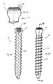
- Bone anchor 50 is a bone screw, which in one embodiment is substantially like the bone screw disclosed in U.S. Patent No. 5,885,286,
- Bone anchor 50 includes an anchorage portion 52 and a head portion 54.
- Anchorage portion 52 includes at least one thread 56, which may be a cancellous self-tapping thread.
- Head portion 54 forms part of a sphere in the illustrated embodiment, though alternative curvate and other configurations may be employed.
- Head 54 in one particular embodiment includes a series of ridges 58 for improving purchase with the inside of crown member 70 (described below).
- Head 54 may have alternative friction-increasing surface configuration(s) such as roughening or knurling. Further, head 54 includes a tool-engaging print 60, with which a tool (not shown) may be engaged to drive anchorage portion 52 into a bone.
- Tool-engaging print 60 is an interior print in the illustrated embodiment, although an exterior print could be used, and it may have any of a number of configurations, such as hexagonal, hexalobate, or other known torque-transferring configurations.
- bone anchor 50 could be a bone-engaging hook rather than a screw.
- anchorage portion 52 would be configured with a hook rather than an elongated section with thread 56.
- Head 54 of bone anchor 50 is shaped and sized to fit within at least lower portion 31 b of opening 32 and chamber 38 of receiver member 30. Specifically, head 54 has a width that is smaller than the width of lower opening portion 31 b and chamber 38. As more fully described below, bone anchor 50 is inserted into receiver member 30, with head 54 entering lower opening portion 31 b and chamber 38 through bottom end 36 of receiver member 30.
- crown member 70 is in the shape of a circular disc, having an upper surface 72 with a beveled edge 74 and a lower surface 78.
- Lower surface 78 is configured to accommodate head 54 of bone anchor 50, and therefore the illustrated embodiment of lower surface 78 has the shape of part of a sphere.
- the lower surface of crown member 70 can have one or more other shapes, such as beveled or conical lower surface 78' (FIG. 5c).
- Lower surface 78 can be provided with a friction- or purchase-enhancing surface configuration (e.g. roughening or knurling) for cooperation with head 54 of bone anchor 50.
- crown member 70 also includes a hole 80. Hole 80 is provided so that head 54, and specifically tool-engaging print 60, of bone anchor 50 may be accessed through crown member 70.
- Crown member 70 is sized and shaped to fit within at least lower portion 31b of opening 32 and chamber 38 of receiver member 30.
- the outer dimension of crown member 70 is preferably slightly smaller than the inner dimension of chamber 38 and lower portion 31 b of opening 32 so that crown member 70 is slidably and rotatably movable within chamber 38 and opening 32. Further, in the illustrated embodiment the outer dimension of crown member 70 is larger than the inner dimension of upper opening portion 31 a, so that crown member 70 cannot move into upper opening portion 31a.
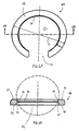
- Retaining member 90 has the form of a C-shaped spring or clip defining a gap 91.
- Retaining member 90 includes a top surface 92 and a bottom surface 94.
- retaining member 90 also includes internal surfaces 96, 98, 100 that substantially surround aperture 102.
- internal surface 96 forms a portion of a sphere of radius substantially identical to the radius of head 54 of bone anchor 50
- internal surface 98 is cylindrical
- internal surface 100 is conical and angled outward to allow a greater range of angular positioning of bone anchor 50.
- aperture 102 there may be single or multiple internal surfaces surrounding aperture 102, which surface(s) may be cylindrical, conical, spherical or of other appropriate configuration.
- the diameter of aperture 102 is smaller than the diameter of head 54 of bone anchor 50 and the diameter of crown member 70.
- Retaining member 90 has an unloaded or natural outer diameter D, i.e. a diameter measured when retaining member 90 is under no contractive (gap-closing) or expansive (gap-opening) stress. Diameter D of retaining member 90, in one embodiment, is less than groove diameter B of groove 41. Further, retaining member 90 has a body width W that is substantially constant throughout retaining member 90. Body width W of retaining member 90 is greater than groove depth A of groove 41.
- assembly 20 is assembled as follows: bone anchor 50, crown member 70 and retaining member 90 are inserted into receiver member 30 through bottom end 36, either individually or substantially in one step.
- crown member 70 may be inserted first, followed by bone anchor 50 with retaining member 90 being inserted last.
- retaining member 90 is fitted around bone anchor 50 just below head 54 prior to insertion of bone anchor 50 into receiver member 30.
- Retaining member 90 can be placed around bone anchor 50 by inserting anchorage portion 52 of bone anchor 50 through aperture 102 of retaining member 90 and moving retaining member 90 over anchorage portion 52 toward head 54.
- gap 91 of retaining member 90 may be pressed against the shank of bone anchor 50 below head 54, so that gap 91 expands to allow placement of bone anchor 50 within aperture 102 of retaining member 90, whereupon retaining member 90 returns to its original size and shape.
- Crown member 70 remains slideably and rotatably positioned in lower portion 31 b of opening 32 and/or chamber 38 of receiving member 30, and bone anchor 50 remains multi-axially moveable with respect to crown member 70 and receiving member 30.
- Retaining member 90 is forced upward into lower portion 31 b of opening 32.
- Retaining member 90 contracts, making gap 91 smaller, as retaining member 90 is forced against chamfered edge 40b of receiving member 30, until the outer diameter of retaining member 90 is the same as the diameter of lower portion 31b of opening 32.
- Retaining member 90 is further advanced along opening 32 and into groove 41 so that retaining member 90 is fitted into at least a portion of groove 41.
- the groove diameter B of groove 41 is smaller than the outer diameter D of retaining member 90 in its natural (i.e., unloaded) condition.
- groove diameter B of groove 41 may be the same size or slightly larger than the natural outer diameter D of retaining member 90.
- the lower surface 94 of retaining member 90 rests upon ledge 41 a of groove 41, and thereby holds retaining member 90 within groove 41.
- Groove depth A of groove 41 is less than the body width W of retaining member 90, so that when retaining member 90 is fitted in groove 41, a portion of retaining member 90 projects into lower opening portion 31 b of opening 32.
- assembly 20 is assembled (as described above) prior to use in a surgical procedure.
- bone anchor 50 of assembly 20 is threaded into an appropriately prepared hole in a bone (not shown).
- Threaded anchoring portion 52 is inserted into the hole, and an appropriate screwing tool is used with tool-engaging print 60 of bone anchor 50 through hole 80 in crown member 70, and bone anchor 50 is threaded into the bone.
- receiver member 30 When bone anchor 50 has been threaded into the bone to the desired depth, receiver member 30 is positioned so that opening 32 forms a desired angle with bone anchor 50, as depicted in FIG. 1.
- the angle ⁇ between bone anchor 50 and opening 32 can be any value up to 30 degrees in any direction. It will be seen that the maximum angle of bone anchor 50 relative to opening 32 can be changed in several ways, for example by thinning the portion of bone anchor 50 beneath head 54, by providing steeper angulation of chamfered edge 40b, and/or by placing groove 41 as close as possible to bottom end of 36 of receiver member 30.
- receiver member 30 may be angled as the surgeon desires with respect to bone anchor 50.
- An elongated member R such as a spinal rod, connector, or other orthopedic surgical implant is coupled with assembly 20. Elongated member R is placed in channel 45 of receiver member 30, and contacts top surface 72 of crown member 70.
- a compression member 120 such as a set screw or threaded plug, is threaded into threads 44 of receiver member 30 and down onto elongated member R.
- Compression member 120 in one embodiment, is a set screw or plug having external threads 122 and a print 124 for applying torque, and in a specific embodiment is a break-off set screw as disclosed in U.S. Patent No. 5,885,286 to Sherman et al.
- thread 122 is a reverse angle thread as disclosed in U.S. Patent No. 6,296,642, filed November 9, 1998, which is compatible with the reverse angle embodiment of thread 44 of receiver member 30, described above.
- compression member 120 could be an internally-threaded nut.
- elongated member R is forced downward against crown member 70, which pushes crown member 70 down onto head 54 of bone anchor 50.
- Head 54 is thereby clamped between retaining member 90 and crown member 70.
- ridges 58 are pressed into lower surface 78 of crown member 70. In this way, bone anchor 50 is locked into the desired angular position with respect to elongated member R and the remainder of assembly 20.
- assembly 20 can be assembled during the surgical procedure. Bone anchor 50, with retaining ring 90 already positioned beneath head 54, is inserted into the bone. Crown member 70 is placed atop bone anchor 50 or in opening 32 in receiver member 30. Receiver member 30 is then pressed down onto head 54 of bone anchor 50, forcing retaining ring 90 to contract, to enter opening 32, and to seat in groove 41 as described above. After assembly 20 is assembled in this fashion, an elongated member is loaded into receiver member 30 and locked as previously described.
- crown member 70 may be made of a material somewhat softer than the material used for ridges 58 of head 54 of bone anchor 50. Such construction will allow ridges 58 to penetrate somewhat more easily into interior surface 78 of crown member 70 during locking of assembly 20, thereby providing a more definite purchase between ridges 58 and crown member 70.
- crown member 70 may be made of a material somewhat softer than the material used for elongated member R. Such construction will allow upper surface 72 of crown member 70 to deform to the shape of elongated member R during locking of assembly 20, also providing a more secure locking of the implant.
Landscapes
- Health & Medical Sciences (AREA)
- Orthopedic Medicine & Surgery (AREA)
- Life Sciences & Earth Sciences (AREA)
- Neurology (AREA)
- Surgery (AREA)
- Heart & Thoracic Surgery (AREA)
- General Health & Medical Sciences (AREA)
- Biomedical Technology (AREA)
- Nuclear Medicine, Radiotherapy & Molecular Imaging (AREA)
- Medical Informatics (AREA)
- Molecular Biology (AREA)
- Animal Behavior & Ethology (AREA)
- Engineering & Computer Science (AREA)
- Public Health (AREA)
- Veterinary Medicine (AREA)
- Surgical Instruments (AREA)
- Control Of Motors That Do Not Use Commutators (AREA)
- Materials For Medical Uses (AREA)
- Pharmaceuticals Containing Other Organic And Inorganic Compounds (AREA)
Claims (40)
- Vorrichtung zum Aufnehmen und Halten von Bestandteilen eines mehrachsigen Knochenankersystems mit einem Element (30), das einen oberen Öffnungsabschnitt (31a) und einen unteren Öffnungsabschnitt (31b) definiert, einem quer dazu verlaufenden Kanal (45), der in Verbindung mit dem oberen Öffnungsabschnitt (31a) und dem unteren Öffnungsabschnitt (31b) steht, einer Nut (41) um mindestens einen Abschnitt des unteren Öffnungsabschnitts (31b), einem Knocheneingriffsanker (50), der einen Kopf (54) aufweist, und einem Halteelement (90), das um mindestens einen Abschnitt des Knocheneingriffsankers (50) angeordnet ist,
dadurch gekennzeichnet, dass
das Halteelement (90) C-förmig ist und unterhalb des Kopfs (54) angeordnet ist. - Vorrichtung nach Anspruch 1, wobei der obere Öffnungsabschnitt und der untere Öffnungsabschnitt zumindest einen Teil einer Öffnung durch das Element von einem oberen zu einem unteren Ende bilden.
- Vorrichtung nach Anspruch 1, wobei die Nut in der Nähe des unteren Endes des Elements liegt.
- Vorrichtung nach Anspruch 2, wobei mindestens ein Abschnitt des oberen Öffnungsabschnitts mit einem Gewinde versehen ist.
- Vorrichtung nach Anspruch 3, wobei das Element zwei Zweige umfasst, die den oberen Öffnungsabschnitt und mindestens einen Abschnitt des Kanals definieren.
- Knochenankeranordnung (20) zum Eingreifen in ein lang gestrecktes Element (R) mit:wobei der Knocheneingriffsanker (50) einen unteren Abschnitt (52) aufweist, der dafür konfiguriert ist, in einen Knochen einzugreifen, und der Kopf (54) eine Breite aufweist, wobei die Breite des Kopfs (54) kleiner ist als die minimale Breite des unteren Öffnungsabschnitts (31b), wobei der Kopf (54) beweglich in dem unteren Öffnungsabschnitt (31b) nächstliegend zu der unteren Fläche (78) des Kronenelements (70) eingerichtet ist, undder Vorrichtung nach Anspruch 1, wobei das Element (30) ein Aufnahmeelement ist, das den oberen Öffnungsabschnitt (31a) und den unteren Öffnungsabschnitt (31b) definiert, die jeweils entsprechende minimale Breiten aufweisen, wobei der Kanal (45) dafür konfiguriert ist, ein lang gestrecktes Element (R) aufzunehmen, wobei die Knochenankeranordnung (20) weiter aufweist:ein Kronenelement (70), das beweglich in dem unteren Öffnungsabschnitt (31b) angeordnet ist, wobei das Kronenelement (70) eine obere Fläche (72) und eine untere Fläche (78) aufweist,
wobei das C-förmige Halteelement (90) einen Durchlass (102) definiert, der kleiner ist als die Breite des Kopfs (54), wobei das Halteelement (90) zumindest teilweise in der Nut (41) des Aufnahmeelements (30) untergebracht ist,
wobei das Halteelement (90) das Entfernen des Kopfs (54) vom unteren Öffnungsabschnitt (31b) verhindert. - Anordnung nach Anspruch 6, wobei der obere Öffnungsabschnitt und der untere Öffnungsabschnitt mindestens einen Teil einer einzigen Öffnung durch das Aufnahmeelement bilden.
- Anordnung nach Anspruch 7, wobei das Aufnahmeelement zwei Zweige aufweist, die den oberen Öffnungsabschnitt und den Kanal definieren.
- Anordnung nach Anspruch 8, wobei die Zweige Innengewinde aufweisen.
- Anordnung nach Anspruch 9, welche weiter ein Kompressionselement aufweist, das schraubenartig mit dem Innengewinde verbunden ist.
- Anordnung nach Anspruch 7, wobei das Aufnahmeelement eine Kammer definiert, die mindestens einen Teil des unteren Öffnungsabschnitts bildet, und wobei das Kronenelement beweglich in der Kammer eingerichtet ist.
- Anordnung nach Anspruch 11, wobei der Anker eine Knochenschraube ist.
- Anordnung nach Anspruch 12, wobei der Kopf der Knochenschraube zumindest teilweise sphärisch ist.
- Anordnung nach Anspruch 13, wobei der Kopf der Knochenschraube Rippen aufweist.
- Anordnung nach Anspruch 13, wobei die untere Fläche des Kronenelements zumindest teilweise sphärisch ist.
- Anordnung nach Anspruch 15, wobei die untere Fläche des Kronenelements einen aufgerauten Abschnitt aufweist.
- Anordnung nach Anspruch 11, wobei das Kronenelement eine Breite aufweist, die größer ist als die obere Öffnung des Aufnahmeelements.
- Anordnung nach Anspruch 17, wobei der Kopf des Knochenankers einen eingedrückten Bereich für den Werkzeugeingriff (engl.: tool-engaging-print) aufweist.
- Anordnung nach Anspruch 18, wobei das Kronenelement ein Loch durch die obere Fläche definiert, durch das der Kopf des Knochenankers zugänglich ist.
- Anordnung nach Anspruch 19, wobei das Halteelement einen unbelasteten Außendurchmesser aufweist, das Aufnahmeelement einen Nutdurchmesser aufweist und der unbelastete Außendurchmesser des Halteelements größer ist als der Nutdurchmesser des Aufnahmeelements.
- Anordnung nach Anspruch 20, wobei das Halteelement eine Körperbreite aufweist, die Nut eine Nuttiefe aufweist und die Körperbreite größer als die Nuttiefe ist.
- Anordnung nach Anspruch 21, wobei das Halteelement eine konkave Innenfläche zum Eingreifen in den Kopf des Knochenankers aufweist.
- Anordnung nach Anspruch 22, wobei die konkave Innenfläche einen Teil einer Kugel ausbildet.
- Anordnung nach Anspruch 7, wobei die untere Fläche des Kronenelements abgeschrägt ist.
- Anordnung nach Anspruch 7, wobei die untere Fläche des Kronenelements konkav ist.
- Anordnung nach Anspruch 7, wobei das Kronenelement eine größere Breite aufweist als der obere Öffnungsabschnitt des Aufnahmeelements.
- Anordnung nach Anspruch 26, wobei das Kronenelement ein Loch durch die obere Fläche definiert, durch das der Kopf des Knochenankers zugänglich ist.
- Anordnung nach Anspruch 1, wobei das Halteelement einen unbelasteten Außendurchmesser aufweist, das Aufnahmeelement einen Nutdurchmesser aufweist und der unbelastete Außendurchmesser des Halteelements größer ist als der Nutdurchmesser des Aufnahmeelements.
- Anordnung nach Anspruch 1, wobei das Halteelement eine Körperbreite aufweist, die Nut eine Nuttiefe aufweist und die Körperbreite größer als die Nuttiefe ist.
- Anordnung nach Anspruch 29, wobei das Halteelement eine konkave Innenfläche zum Eingreifen mit dem Kopf des Knochenankers aufweist.
- Anordnung nach Anspruch 30, wobei die konkave Innenfläche einen Teil einer Kugel ausbildet.
- Knochenbefestigungsvorrichtung mit:wobei der Knochenanker (50) einen unteren Abschnitt (52), der zum Eingreifen in einen Knochen konfiguriert ist, und einen Kopf (54) mit einer Breitenabmessung aufweist, wobei der Kopf (54) durch den unteren Durchlass (31b) einführbar ist und nächstliegend dem Kronenelement (70) innerhalb der Öffnung (32) des Aufnahmeelements (30) ist,einem lang gestreckten Element (R), das zur Anordnung nächstliegend zu mindestens einem Knochen und entlang diesem konfiguriert ist,der Vorrichtung nach Anspruch 1, wobei das Element (30) ein Aufnahmeelement ist, das von einem oberen Ende zu einem unteren Ende eine Öffnung (32) da hindurch definiert, wobei die Öffnung einen unteren Durchlass (31b) an dem unteren Ende und einen oberen Durchlass (31a) an dem oberen Ende aufweist, wobei das Aufnahmeelement auch die Nut (41) um einen Abschnitt der Öffnung (32) definiert, wobei die Nut (41) in der Nähe des unteren Durchlasses (31b) verläuft, wobei das Aufnahmeelement (30) weiterhin den Kanal (45) umfasst, der mit der Öffnung (32) und dem oberen Durchlass (31a) in Verbindung steht, wobei der Kanal (45) dafür konfiguriert ist, das lang gestreckte Element (R) darin aufzunehmen, wobei die Vorrichtung weiterhin aufweist:ein Kronenelement (70), das durch den unteren Durchlass (31a)1 einführbar ist und innerhalb der Öffnung (32) angeordnet ist, wobei das Kronenelement (70) eine untere Fläche (78) und eine gegenüberliegende obere Fläche (72) aufweist, die das lang gestreckte Element (R) berührt,
wobei das C-förmige Halteelement (90) einen Durchlass (102) definiert, der eine Breitenabmessung aufweist, die kleiner ist als die Breitenabmessung des Kopfs (54), und mindestens ein Abschnitt des Halteelements (90) innerhalb mindestens eines Abschnitts der Nut (41) beherbergt ist, und ein Kompressionselement (120), das in der Nähe des oberen Durchlasses (31a) in die Öffnung (32) eingreift, wobei das Kompressionselement (120) betriebsfähig bzw. wirksam ist, um das lang gestreckte Element (R) gegen das Kronenelement (70) zu drücken und dadurch den Kopf (54) des Knochenankers (50) zwischen dem Kronenelement (70) und dem Halteelement (90) zu fixieren. - Vorrichtung nach Anspruch 32, wobei das lang gestreckte Element eine Wirbelsäulenstange ist.
- Vorrichtung nach Anspruch 33, wobei das Halteelement einen unbelasteten Außendurchmesser aufweist, das Aufnahmeelement einen Nutdurchmesser aufweist und der unbelastete Außendurchmesser des Halteelements größer ist als der Nutdurchmesser des Aufnahmeelements.
- Vorrichtung nach Anspruch 34, wobei das Halteelement eine Körperbreite aufweist, die Nut eine Nuttiefe aufweist und die Körperbreite größer als die Nuttiefe ist.
- Vorrichtung nach Anspruch 35, wobei das Halteelement eine konkave Innenfläche zum Eingreifen mit dem Kopf des Knochenankers aufweist.
- Vorrichtung nach Anspruch 36, wobei die konkave Innenfläche einen Teil einer Kugel ausbildet.
- Vorrichtung nach Anspruch 31, wobei das Kronenelement ein Loch durch die obere Fläche definiert, durch das der Kopf des Knochenankers zugänglich ist.
- Vorrichtung nach Anspruch 31, wobei der Kopf des Knochenankers zumindest teilweise sphärisch ist.
- Vorrichtung nach Anspruch 39, wobei die untere Fläche des Kronenelements zumindest teilweise sphärisch ist.
Applications Claiming Priority (3)
| Application Number | Priority Date | Filing Date | Title |
|---|---|---|---|
| US387991 | 1999-09-01 | ||
| US09/387,991 US6280442B1 (en) | 1999-09-01 | 1999-09-01 | Multi-axial bone screw assembly |
| PCT/US2000/040771 WO2001015612A1 (en) | 1999-09-01 | 2000-08-29 | Multi-axial bone screw assembly |
Publications (2)
| Publication Number | Publication Date |
|---|---|
| EP1214006A1 EP1214006A1 (de) | 2002-06-19 |
| EP1214006B1 true EP1214006B1 (de) | 2005-10-19 |
Family
ID=23532168
Family Applications (1)
| Application Number | Title | Priority Date | Filing Date |
|---|---|---|---|
| EP00971073A Expired - Lifetime EP1214006B1 (de) | 1999-09-01 | 2000-08-29 | Polyaxiale knochenschraubenanordnung |
Country Status (10)
| Country | Link |
|---|---|
| US (5) | US6280442B1 (de) |
| EP (1) | EP1214006B1 (de) |
| JP (1) | JP4318421B2 (de) |
| CN (1) | CN1192749C (de) |
| AT (1) | ATE306854T1 (de) |
| AU (1) | AU773530B2 (de) |
| CA (1) | CA2382033C (de) |
| DE (1) | DE60023323T2 (de) |
| ES (1) | ES2250201T3 (de) |
| WO (1) | WO2001015612A1 (de) |
Cited By (5)
| Publication number | Priority date | Publication date | Assignee | Title |
|---|---|---|---|---|
| US8535318B2 (en) | 2010-04-23 | 2013-09-17 | DePuy Synthes Products, LLC | Minimally invasive instrument set, devices and related methods |
| US9314274B2 (en) | 2011-05-27 | 2016-04-19 | DePuy Synthes Products, Inc. | Minimally invasive spinal fixation system including vertebral alignment features |
| DE102014222890A1 (de) | 2014-11-10 | 2016-05-12 | Premiere Medical Gmbh | Pedikelschraube und Pedikelschraubensystem |
| US9498262B2 (en) | 2006-04-11 | 2016-11-22 | DePuy Synthes Products, Inc. | Minimally invasive fixation system |
| US9808281B2 (en) | 2009-05-20 | 2017-11-07 | DePuy Synthes Products, Inc. | Patient-mounted retraction |
Families Citing this family (571)
| Publication number | Priority date | Publication date | Assignee | Title |
|---|---|---|---|---|
| US5875288A (en) * | 1990-02-05 | 1999-02-23 | Scitex Corporation Ltd. | Apparatus and techniques for computerized printing |
| US6485494B1 (en) * | 1996-12-20 | 2002-11-26 | Thomas T. Haider | Pedicle screw system for osteosynthesis |
| FR2796545B1 (fr) * | 1999-07-22 | 2002-03-15 | Dimso Sa | Liaison poly-axiale pour systeme d'osteosynthese, notamment pour le rachis |
| US6280442B1 (en) * | 1999-09-01 | 2001-08-28 | Sdgi Holdings, Inc. | Multi-axial bone screw assembly |
| DE10005385A1 (de) * | 2000-02-07 | 2001-08-09 | Ulrich Gmbh & Co Kg | Pedikelschraube |
| US6235033B1 (en) * | 2000-04-19 | 2001-05-22 | Synthes (Usa) | Bone fixation assembly |
| US7985247B2 (en) * | 2000-08-01 | 2011-07-26 | Zimmer Spine, Inc. | Methods and apparatuses for treating the spine through an access device |
| US7056321B2 (en) | 2000-08-01 | 2006-06-06 | Endius, Incorporated | Method of securing vertebrae |
| US7833250B2 (en) | 2004-11-10 | 2010-11-16 | Jackson Roger P | Polyaxial bone screw with helically wound capture connection |
| US7837716B2 (en) * | 2000-08-23 | 2010-11-23 | Jackson Roger P | Threadform for medical implant closure |
| US20060025771A1 (en) * | 2000-08-23 | 2006-02-02 | Jackson Roger P | Helical reverse angle guide and advancement structure with break-off extensions |
| US8512380B2 (en) * | 2002-08-28 | 2013-08-20 | Warsaw Orthopedic, Inc. | Posterior fixation system |
| US6485491B1 (en) * | 2000-09-15 | 2002-11-26 | Sdgi Holdings, Inc. | Posterior fixation system |
| ATE296580T1 (de) * | 2000-09-18 | 2005-06-15 | Zimmer Gmbh | Pedikelschraube für intervertebrale stützelemente |
| DE10055888C1 (de) | 2000-11-10 | 2002-04-25 | Biedermann Motech Gmbh | Knochenschraube |
| US6368321B1 (en) * | 2000-12-04 | 2002-04-09 | Roger P. Jackson | Lockable swivel head bone screw |
| US8377100B2 (en) * | 2000-12-08 | 2013-02-19 | Roger P. Jackson | Closure for open-headed medical implant |
| US6726689B2 (en) | 2002-09-06 | 2004-04-27 | Roger P. Jackson | Helical interlocking mating guide and advancement structure |
| US6488681B2 (en) | 2001-01-05 | 2002-12-03 | Stryker Spine S.A. | Pedicle screw assembly |
| US6969610B2 (en) * | 2001-01-12 | 2005-11-29 | University Of Rochester | Methods of modifying cell structure and remodeling tissue |
| FR2822053B1 (fr) | 2001-03-15 | 2003-06-20 | Stryker Spine Sa | Organe d'ancrage avec bague de securite pour systeme d'osteosynthese rachidienne |
| US8353932B2 (en) * | 2005-09-30 | 2013-01-15 | Jackson Roger P | Polyaxial bone anchor assembly with one-piece closure, pressure insert and plastic elongate member |
| US7862587B2 (en) | 2004-02-27 | 2011-01-04 | Jackson Roger P | Dynamic stabilization assemblies, tool set and method |
| US10258382B2 (en) | 2007-01-18 | 2019-04-16 | Roger P. Jackson | Rod-cord dynamic connection assemblies with slidable bone anchor attachment members along the cord |
| US8292926B2 (en) | 2005-09-30 | 2012-10-23 | Jackson Roger P | Dynamic stabilization connecting member with elastic core and outer sleeve |
| US10729469B2 (en) | 2006-01-09 | 2020-08-04 | Roger P. Jackson | Flexible spinal stabilization assembly with spacer having off-axis core member |
| US20160242816A9 (en) | 2001-05-09 | 2016-08-25 | Roger P. Jackson | Dynamic spinal stabilization assembly with elastic bumpers and locking limited travel closure mechanisms |
| US7314467B2 (en) | 2002-04-24 | 2008-01-01 | Medical Device Advisory Development Group, Llc. | Multi selective axis spinal fixation system |
| US6770075B2 (en) | 2001-05-17 | 2004-08-03 | Robert S. Howland | Spinal fixation apparatus with enhanced axial support and methods for use |
| CH695478A5 (de) * | 2001-07-20 | 2006-06-15 | Werner Hermann | Gewindebolzen, Pedrikelschraube und Pedrikelschraube mit Gewindebolzen |
| US6520963B1 (en) | 2001-08-13 | 2003-02-18 | Mckinley Lawrence M. | Vertebral alignment and fixation assembly |
| EP1418853B1 (de) * | 2001-08-13 | 2011-02-16 | McKinley, Laurence M. | Wirbelausrichtungs- und fixierungsanordnung |
| US6974460B2 (en) | 2001-09-14 | 2005-12-13 | Stryker Spine | Biased angulation bone fixation assembly |
| KR100379194B1 (en) * | 2001-10-31 | 2003-04-08 | U & I Co Ltd | Apparatus for fixing bone |
| WO2003041601A1 (de) * | 2001-11-14 | 2003-05-22 | Synthes Ag Chur | Vorrichtung zur verbindung eines längsträgers mit einem knochenfixationsmittel |
| FR2832308B1 (fr) * | 2001-11-22 | 2004-09-24 | Guillaume Derouet | Implant orthopedique constitue d'une structure support munie d'au moins un orifice pour le passage d'une vis de fixation associee a un ecrou |
| DE10157969C1 (de) * | 2001-11-27 | 2003-02-06 | Biedermann Motech Gmbh | Element mit einem Schaft und einem damit verbundenen Halteelement zum Verbinden mit einem Stab |
| AU2002220448B2 (en) * | 2001-12-24 | 2005-06-30 | Synthes Gmbh | Device for performing osteosynthesis |
| CN1432343A (zh) * | 2002-01-17 | 2003-07-30 | 英属维京群岛商冠亚生技控股集团股份有限公司 | 脊椎固定用旋控式固定装置 |
| US6837889B2 (en) | 2002-03-01 | 2005-01-04 | Endius Incorporated | Apparatus for connecting a longitudinal member to a bone portion |
| US7066937B2 (en) * | 2002-02-13 | 2006-06-27 | Endius Incorporated | Apparatus for connecting a longitudinal member to a bone portion |
| US7879075B2 (en) | 2002-02-13 | 2011-02-01 | Zimmer Spine, Inc. | Methods for connecting a longitudinal member to a bone portion |
| US7294128B2 (en) * | 2002-04-09 | 2007-11-13 | Nas Medical Technologies, Inc. | Bone fixation apparatus |
| US6740086B2 (en) | 2002-04-18 | 2004-05-25 | Spinal Innovations, Llc | Screw and rod fixation assembly and device |
| US7842073B2 (en) * | 2002-04-18 | 2010-11-30 | Aesculap Ii, Inc. | Screw and rod fixation assembly and device |
| CN101200450A (zh) * | 2002-04-30 | 2008-06-18 | Ucb公司 | 2,6-喹啉基和2,6-萘基衍生物、用于制备它们的方法和它们作为vla-4抑制剂的用途 |
| US11224464B2 (en) | 2002-05-09 | 2022-01-18 | Roger P. Jackson | Threaded closure with inwardly-facing tool engaging concave radiused structures and axial through-aperture |
| US8257402B2 (en) | 2002-09-06 | 2012-09-04 | Jackson Roger P | Closure for rod receiving orthopedic implant having left handed thread removal |
| US8282673B2 (en) | 2002-09-06 | 2012-10-09 | Jackson Roger P | Anti-splay medical implant closure with multi-surface removal aperture |
| US8876868B2 (en) | 2002-09-06 | 2014-11-04 | Roger P. Jackson | Helical guide and advancement flange with radially loaded lip |
| US20060009773A1 (en) * | 2002-09-06 | 2006-01-12 | Jackson Roger P | Helical interlocking mating guide and advancement structure |
| DE10246177A1 (de) * | 2002-10-02 | 2004-04-22 | Biedermann Motech Gmbh | Verankerungselement |
| US9539012B2 (en) | 2002-10-30 | 2017-01-10 | Zimmer Spine, Inc. | Spinal stabilization systems with quick-connect sleeve assemblies for use in surgical procedures |
| EP3222231A1 (de) | 2002-10-30 | 2017-09-27 | Zimmer Spine, Inc. | Spinaler stabilisierungssystemeinsatz und verfahren |
| US8162989B2 (en) * | 2002-11-04 | 2012-04-24 | Altus Partners, Llc | Orthopedic rod system |
| KR100495876B1 (ko) * | 2002-11-25 | 2005-06-16 | 유앤아이 주식회사 | 뼈 고정장치와 조립방법 및 시술 공구 |
| US20040111088A1 (en) * | 2002-12-06 | 2004-06-10 | Picetti George D. | Multi-rod bone attachment member |
| US7887539B2 (en) | 2003-01-24 | 2011-02-15 | Depuy Spine, Inc. | Spinal rod approximators |
| US7686837B2 (en) * | 2003-02-03 | 2010-03-30 | Stryker Trauma S.A. | Polyaxial locking implantable orthopedic fixation device |
| WO2007035884A2 (en) * | 2005-09-20 | 2007-03-29 | Pioneer Surgical Technology, Inc. | Spinal fixation systems |
| US7141051B2 (en) | 2003-02-05 | 2006-11-28 | Pioneer Laboratories, Inc. | Low profile spinal fixation system |
| US20040162558A1 (en) | 2003-02-18 | 2004-08-19 | Hegde Sajan K. | Spinal plate having an integral rod connector portion |
| DE10310540B3 (de) * | 2003-03-11 | 2004-08-19 | Biedermann Motech Gmbh | Verankerungselement zur Verwendung in der Wirbelsäulen- oder Knochenchirurgie und Verfahren zu seiner Herstellung |
| US20040186473A1 (en) * | 2003-03-21 | 2004-09-23 | Cournoyer John R. | Spinal fixation devices of improved strength and rigidity |
| US7621918B2 (en) | 2004-11-23 | 2009-11-24 | Jackson Roger P | Spinal fixation tool set and method |
| US8052724B2 (en) * | 2003-06-18 | 2011-11-08 | Jackson Roger P | Upload shank swivel head bone screw spinal implant |
| US8540753B2 (en) | 2003-04-09 | 2013-09-24 | Roger P. Jackson | Polyaxial bone screw with uploaded threaded shank and method of assembly and use |
| US6716214B1 (en) | 2003-06-18 | 2004-04-06 | Roger P. Jackson | Polyaxial bone screw with spline capture connection |
| US6964666B2 (en) * | 2003-04-09 | 2005-11-15 | Jackson Roger P | Polyaxial bone screw locking mechanism |
| US20040210216A1 (en) * | 2003-04-17 | 2004-10-21 | Farris Robert A | Spinal fixation system and method |
| DE10320417A1 (de) | 2003-05-07 | 2004-12-02 | Biedermann Motech Gmbh | Dynamische Verankerungsvorrichtung und dynamische Stabilisierungseinrichtung für Knochen, insbesondere für Wirbel, mit einer derartigen Verankerungsvorrichtung |
| DE20307776U1 (de) * | 2003-05-19 | 2004-09-23 | Metz-Stavenhagen, Peter, Dr.med. | Verankerungselement zur Befestigung eines Stabes einer Vorrichtung zum Einrichten einer menschlichen oder tierischen Wirbelsäule an einem Wirbelknochen |
| US7377923B2 (en) | 2003-05-22 | 2008-05-27 | Alphatec Spine, Inc. | Variable angle spinal screw assembly |
| FR2855392B1 (fr) * | 2003-05-28 | 2005-08-05 | Spinevision | Dispositif de connexion pour ostesynthese rachidienne |
| US7766915B2 (en) | 2004-02-27 | 2010-08-03 | Jackson Roger P | Dynamic fixation assemblies with inner core and outer coil-like member |
| US8137386B2 (en) * | 2003-08-28 | 2012-03-20 | Jackson Roger P | Polyaxial bone screw apparatus |
| US8936623B2 (en) | 2003-06-18 | 2015-01-20 | Roger P. Jackson | Polyaxial bone screw assembly |
| US20100211114A1 (en) * | 2003-06-18 | 2010-08-19 | Jackson Roger P | Polyaxial bone anchor with shelf capture connection |
| US7322981B2 (en) * | 2003-08-28 | 2008-01-29 | Jackson Roger P | Polyaxial bone screw with split retainer ring |
| US8257398B2 (en) * | 2003-06-18 | 2012-09-04 | Jackson Roger P | Polyaxial bone screw with cam capture |
| US7776067B2 (en) | 2005-05-27 | 2010-08-17 | Jackson Roger P | Polyaxial bone screw with shank articulation pressure insert and method |
| US8377102B2 (en) | 2003-06-18 | 2013-02-19 | Roger P. Jackson | Polyaxial bone anchor with spline capture connection and lower pressure insert |
| US8398682B2 (en) | 2003-06-18 | 2013-03-19 | Roger P. Jackson | Polyaxial bone screw assembly |
| US8092500B2 (en) | 2007-05-01 | 2012-01-10 | Jackson Roger P | Dynamic stabilization connecting member with floating core, compression spacer and over-mold |
| US8366753B2 (en) | 2003-06-18 | 2013-02-05 | Jackson Roger P | Polyaxial bone screw assembly with fixed retaining structure |
| US7967850B2 (en) * | 2003-06-18 | 2011-06-28 | Jackson Roger P | Polyaxial bone anchor with helical capture connection, insert and dual locking assembly |
| FR2856271B1 (fr) * | 2003-06-23 | 2005-12-30 | Charles Khalife | Plaque d'osteosynthese rachidienne a tete adaptable |
| US7087057B2 (en) * | 2003-06-27 | 2006-08-08 | Depuy Acromed, Inc. | Polyaxial bone screw |
| US6945975B2 (en) * | 2003-07-07 | 2005-09-20 | Aesculap, Inc. | Bone fixation assembly and method of securement |
| US6945974B2 (en) * | 2003-07-07 | 2005-09-20 | Aesculap Inc. | Spinal stabilization implant and method of application |
| US6981973B2 (en) * | 2003-08-11 | 2006-01-03 | Mckinley Laurence M | Low profile vertebral alignment and fixation assembly |
| CA2536336C (en) | 2003-08-20 | 2012-04-10 | Sdgi Holdings, Inc. | Multi-axial orthopedic device and system, e.g. for spinal surgery |
| US7875060B2 (en) * | 2003-09-24 | 2011-01-25 | Spinefrontier, LLS | Multi-axial screw with a spherical landing |
| US7967826B2 (en) | 2003-10-21 | 2011-06-28 | Theken Spine, Llc | Connector transfer tool for internal structure stabilization systems |
| US7588575B2 (en) | 2003-10-21 | 2009-09-15 | Innovative Spinal Technologies | Extension for use with stabilization systems for internal structures |
| US8926700B2 (en) * | 2003-12-10 | 2015-01-06 | Gmedelware 2 LLC | Spinal facet joint implant |
| TW200518711A (en) * | 2003-12-11 | 2005-06-16 | A Spine Holding Group Corp | Rotation buckling ball-head spine restoring equipment |
| US7179261B2 (en) | 2003-12-16 | 2007-02-20 | Depuy Spine, Inc. | Percutaneous access devices and bone anchor assemblies |
| US11419642B2 (en) | 2003-12-16 | 2022-08-23 | Medos International Sarl | Percutaneous access devices and bone anchor assemblies |
| US7527638B2 (en) | 2003-12-16 | 2009-05-05 | Depuy Spine, Inc. | Methods and devices for minimally invasive spinal fixation element placement |
| EP2050407A1 (de) * | 2003-12-30 | 2009-04-22 | DePuy Spine Sàrl | Knochenankeranordnungen |
| EP1699371A4 (de) * | 2003-12-30 | 2008-09-24 | Depuy Spine Sarl | Knochenankeranordnungen |
| US7678137B2 (en) | 2004-01-13 | 2010-03-16 | Life Spine, Inc. | Pedicle screw constructs for spine fixation systems |
| US7993373B2 (en) | 2005-02-22 | 2011-08-09 | Hoy Robert W | Polyaxial orthopedic fastening apparatus |
| US7311712B2 (en) | 2004-02-26 | 2007-12-25 | Aesculap Implant Systems, Inc. | Polyaxial locking screw plate assembly |
| US7789896B2 (en) | 2005-02-22 | 2010-09-07 | Jackson Roger P | Polyaxial bone screw assembly |
| US7892257B2 (en) * | 2004-02-27 | 2011-02-22 | Custom Spine, Inc. | Spring loaded, load sharing polyaxial pedicle screw assembly and method |
| US7163539B2 (en) * | 2004-02-27 | 2007-01-16 | Custom Spine, Inc. | Biased angle polyaxial pedicle screw assembly |
| US8152810B2 (en) | 2004-11-23 | 2012-04-10 | Jackson Roger P | Spinal fixation tool set and method |
| US7819902B2 (en) * | 2004-02-27 | 2010-10-26 | Custom Spine, Inc. | Medialised rod pedicle screw assembly |
| US11241261B2 (en) | 2005-09-30 | 2022-02-08 | Roger P Jackson | Apparatus and method for soft spinal stabilization using a tensionable cord and releasable end structure |
| WO2005092218A1 (en) | 2004-02-27 | 2005-10-06 | Jackson Roger P | Orthopedic implant rod reduction tool set and method |
| US7862594B2 (en) * | 2004-02-27 | 2011-01-04 | Custom Spine, Inc. | Polyaxial pedicle screw assembly |
| US7160300B2 (en) | 2004-02-27 | 2007-01-09 | Jackson Roger P | Orthopedic implant rod reduction tool set and method |
| DE102004010380A1 (de) | 2004-03-03 | 2005-09-22 | Biedermann Motech Gmbh | Verankerungselement und Stabilisierungseinrichtung zur dynamischen Stabilisierung von Wirbeln bzw. Knochen mit einem solchen Verankerungselement |
| EP1570794A1 (de) | 2004-03-04 | 2005-09-07 | U & I Corporation | Knochenfixationsvorrichtung, Verfahren und Werkzeug für dessen Zusammenbau |
| US20050216027A1 (en) * | 2004-03-24 | 2005-09-29 | Suh Sean S | Extraction screwdriver |
| US8475495B2 (en) | 2004-04-08 | 2013-07-02 | Globus Medical | Polyaxial screw |
| US7503924B2 (en) | 2004-04-08 | 2009-03-17 | Globus Medical, Inc. | Polyaxial screw |
| US20050228380A1 (en) * | 2004-04-09 | 2005-10-13 | Depuy Spine Inc. | Instruments and methods for minimally invasive spine surgery |
| US20050228382A1 (en) * | 2004-04-12 | 2005-10-13 | Marc Richelsoph | Screw and rod fixation assembly and device |
| US7789899B2 (en) * | 2004-12-30 | 2010-09-07 | Warsaw Orthopedic, Inc. | Bone anchorage screw with built-in hinged plate |
| US7648520B2 (en) * | 2004-04-16 | 2010-01-19 | Kyphon Sarl | Pedicle screw assembly |
| US7811311B2 (en) * | 2004-12-30 | 2010-10-12 | Warsaw Orthopedic, Inc. | Screw with deployable interlaced dual rods |
| US7618418B2 (en) * | 2004-04-16 | 2009-11-17 | Kyphon Sarl | Plate system for minimally invasive support of the spine |
| US7524323B2 (en) * | 2004-04-16 | 2009-04-28 | Kyphon Sarl | Subcutaneous support |
| US7678139B2 (en) * | 2004-04-20 | 2010-03-16 | Allez Spine, Llc | Pedicle screw assembly |
| US7942912B2 (en) * | 2004-05-25 | 2011-05-17 | University Of Utah Research Foundation | Occipitocervical plate |
| US8241337B2 (en) * | 2004-05-25 | 2012-08-14 | Brockmeyer Douglas L | Occipitocervical plate |
| US7559943B2 (en) * | 2004-06-09 | 2009-07-14 | Zimmer Spine, Inc. | Spinal fixation device with internal drive structure |
| US7935135B2 (en) * | 2004-06-09 | 2011-05-03 | Zimmer Spine, Inc. | Spinal fixation device |
| US7857834B2 (en) | 2004-06-14 | 2010-12-28 | Zimmer Spine, Inc. | Spinal implant fixation assembly |
| US7727266B2 (en) | 2004-06-17 | 2010-06-01 | Warsaw Orthopedic, Inc. | Method and apparatus for retaining screws in a plate |
| US7264621B2 (en) * | 2004-06-17 | 2007-09-04 | Sdgi Holdings, Inc. | Multi-axial bone attachment assembly |
| WO2006005198A1 (de) * | 2004-07-12 | 2006-01-19 | Synthes Gmbh | Vorrichtung zur dynamischen fixierung von knochen |
| DE102004046163A1 (de) | 2004-08-12 | 2006-02-23 | Columbus Trading-Partners Pos und Brendel GbR (vertretungsberechtigte Gesellschafter Karin Brendel, 95503 Hummeltal und Bohumila Pos, 95445 Bayreuth) | Kindersitz für Kraftfahrzeuge |
| US8491634B2 (en) * | 2004-08-13 | 2013-07-23 | Ricardo C. Sasso | Replacement facet joint and method |
| US7846184B2 (en) * | 2004-08-13 | 2010-12-07 | Sasso Ricardo C | Replacement facet joint and method |
| US20060052786A1 (en) * | 2004-08-17 | 2006-03-09 | Zimmer Spine, Inc. | Polyaxial device for spine stabilization during osteosynthesis |
| US20060052784A1 (en) * | 2004-08-17 | 2006-03-09 | Zimmer Spine, Inc. | Polyaxial device for spine stabilization during osteosynthesis |
| US20060052783A1 (en) * | 2004-08-17 | 2006-03-09 | Dant Jack A | Polyaxial device for spine stabilization during osteosynthesis |
| US20060058788A1 (en) * | 2004-08-27 | 2006-03-16 | Hammer Michael A | Multi-axial connection system |
| US8951290B2 (en) * | 2004-08-27 | 2015-02-10 | Blackstone Medical, Inc. | Multi-axial connection system |
| US7651502B2 (en) | 2004-09-24 | 2010-01-26 | Jackson Roger P | Spinal fixation tool set and method for rod reduction and fastener insertion |
| US7794477B2 (en) * | 2004-10-05 | 2010-09-14 | Warsaw Orthopedic, Inc. | Spinal implants and methods with extended multi-axial anchor assemblies |
| US7722654B2 (en) * | 2004-10-05 | 2010-05-25 | Warsaw Orthopedic, Inc. | Spinal implants with multi-axial anchor assembly and methods |
| US7572280B2 (en) * | 2004-10-05 | 2009-08-11 | Warsaw Orthopedic, Inc. | Multi-axial anchor assemblies for spinal implants and methods |
| US8267969B2 (en) * | 2004-10-20 | 2012-09-18 | Exactech, Inc. | Screw systems and methods for use in stabilization of bone structures |
| US8226690B2 (en) | 2005-07-22 | 2012-07-24 | The Board Of Trustees Of The Leland Stanford Junior University | Systems and methods for stabilization of bone structures |
| US8366747B2 (en) * | 2004-10-20 | 2013-02-05 | Zimmer Spine, Inc. | Apparatus for connecting a longitudinal member to a bone portion |
| US7604655B2 (en) | 2004-10-25 | 2009-10-20 | X-Spine Systems, Inc. | Bone fixation system and method for using the same |
| WO2006047707A2 (en) * | 2004-10-25 | 2006-05-04 | Alphaspine, Inc. | Pedicle screw systems and methods of assembling/installing the same |
| US20060161152A1 (en) * | 2004-10-25 | 2006-07-20 | Alphaspine, Inc. | Bone fixation systems and methods of assembling and/or installing the same |
| KR20070084138A (ko) | 2004-10-25 | 2007-08-24 | 알파스파인, 아이엔씨. | 척추경 나사 시스템 및 이의 조립/장착 방법 |
| US7691129B2 (en) * | 2004-10-27 | 2010-04-06 | Felix Brent A | Spinal stabilizing system |
| US7513905B2 (en) * | 2004-11-03 | 2009-04-07 | Jackson Roger P | Polyaxial bone screw |
| JP2008519656A (ja) | 2004-11-10 | 2008-06-12 | ロジャー・ピー・ジャクソン | 破断伸張部付の螺旋状案内及び前進フランジ |
| US8926672B2 (en) | 2004-11-10 | 2015-01-06 | Roger P. Jackson | Splay control closure for open bone anchor |
| US7572279B2 (en) | 2004-11-10 | 2009-08-11 | Jackson Roger P | Polyaxial bone screw with discontinuous helically wound capture connection |
| DE102004055454A1 (de) * | 2004-11-17 | 2006-05-24 | Biedermann Motech Gmbh | Elastisches Element zur Verwendung in einer Stabilisierungseinrichtung für Knochen oder Wirbel |
| US7875065B2 (en) | 2004-11-23 | 2011-01-25 | Jackson Roger P | Polyaxial bone screw with multi-part shank retainer and pressure insert |
| US9216041B2 (en) | 2009-06-15 | 2015-12-22 | Roger P. Jackson | Spinal connecting members with tensioned cords and rigid sleeves for engaging compression inserts |
| US9168069B2 (en) | 2009-06-15 | 2015-10-27 | Roger P. Jackson | Polyaxial bone anchor with pop-on shank and winged insert with lower skirt for engaging a friction fit retainer |
| US20120029568A1 (en) * | 2006-01-09 | 2012-02-02 | Jackson Roger P | Spinal connecting members with radiused rigid sleeves and tensioned cords |
| CA2587630C (en) * | 2004-11-23 | 2010-10-26 | Roger P. Jackson | Polyaxial bone screw with multi-part shank retainer |
| US8308782B2 (en) | 2004-11-23 | 2012-11-13 | Jackson Roger P | Bone anchors with longitudinal connecting member engaging inserts and closures for fixation and optional angulation |
| US8444681B2 (en) | 2009-06-15 | 2013-05-21 | Roger P. Jackson | Polyaxial bone anchor with pop-on shank, friction fit retainer and winged insert |
| WO2006057837A1 (en) | 2004-11-23 | 2006-06-01 | Jackson Roger P | Spinal fixation tool attachment structure |
| US9980753B2 (en) | 2009-06-15 | 2018-05-29 | Roger P Jackson | pivotal anchor with snap-in-place insert having rotation blocking extensions |
| US8172855B2 (en) | 2004-11-24 | 2012-05-08 | Abdou M S | Devices and methods for inter-vertebral orthopedic device placement |
| US7404818B2 (en) * | 2004-11-30 | 2008-07-29 | Warsaw Orthopedic, Inc. | Side-loading adjustable bone anchor |
| US7674277B2 (en) * | 2004-12-01 | 2010-03-09 | Warsaw Orthopedic, Inc. | Side-loading bone anchor |
| US8597331B2 (en) * | 2004-12-10 | 2013-12-03 | Life Spine, Inc. | Prosthetic spinous process and method |
| US7306606B2 (en) * | 2004-12-15 | 2007-12-11 | Orthopaedic Innovations, Inc. | Multi-axial bone screw mechanism |
| US8267967B2 (en) * | 2004-12-15 | 2012-09-18 | Stryker Spine | Methods and apparatus for modular and variable spinal fixation |
| US7744636B2 (en) * | 2004-12-16 | 2010-06-29 | Aesculap Ii, Inc. | Locking mechanism |
| US7445627B2 (en) * | 2005-01-31 | 2008-11-04 | Alpinespine, Llc | Polyaxial pedicle screw assembly |
| US12102357B2 (en) | 2005-02-22 | 2024-10-01 | Roger P. Jackson | Pivotal bone anchor assembly with cannulated shank having a planar top surface and method of assembly |
| US7476239B2 (en) * | 2005-05-10 | 2009-01-13 | Jackson Roger P | Polyaxial bone screw with compound articulation |
| US7901437B2 (en) * | 2007-01-26 | 2011-03-08 | Jackson Roger P | Dynamic stabilization member with molded connection |
| US10076361B2 (en) * | 2005-02-22 | 2018-09-18 | Roger P. Jackson | Polyaxial bone screw with spherical capture, compression and alignment and retention structures |
| US8403962B2 (en) | 2005-02-22 | 2013-03-26 | Roger P. Jackson | Polyaxial bone screw assembly |
| US7951172B2 (en) * | 2005-03-04 | 2011-05-31 | Depuy Spine Sarl | Constrained motion bone screw assembly |
| US7951175B2 (en) | 2005-03-04 | 2011-05-31 | Depuy Spine, Inc. | Instruments and methods for manipulating a vertebra |
| US8696707B2 (en) * | 2005-03-08 | 2014-04-15 | Zyga Technology, Inc. | Facet joint stabilization |
| US7338491B2 (en) * | 2005-03-22 | 2008-03-04 | Spinefrontier Inc | Spinal fixation locking mechanism |
| CA2601948A1 (en) * | 2005-03-25 | 2006-10-05 | Blackstone Medical, Inc. | Multi-axial connection system |
| US8221472B2 (en) * | 2005-04-25 | 2012-07-17 | Synthes Usa, Llc | Bone anchor with locking cap and method of spinal fixation |
| EP1876975A2 (de) | 2005-04-27 | 2008-01-16 | James Marino | Verfahren, system und satz mit einer monoplanaren pedikelschraube |
| US20060247631A1 (en) * | 2005-04-27 | 2006-11-02 | Ahn Sae Y | Spinal pedicle screw assembly |
| US7811310B2 (en) | 2005-05-04 | 2010-10-12 | Spinefrontier, Inc | Multistage spinal fixation locking mechanism |
| WO2007011431A2 (en) * | 2005-07-18 | 2007-01-25 | Dong Myung Jeon | Bi-polar bone screw assembly |
| US8523865B2 (en) * | 2005-07-22 | 2013-09-03 | Exactech, Inc. | Tissue splitter |
| US7766946B2 (en) * | 2005-07-27 | 2010-08-03 | Frank Emile Bailly | Device for securing spinal rods |
| US7717943B2 (en) * | 2005-07-29 | 2010-05-18 | X-Spine Systems, Inc. | Capless multiaxial screw and spinal fixation assembly and method |
| US7625394B2 (en) * | 2005-08-05 | 2009-12-01 | Warsaw Orthopedic, Inc. | Coupling assemblies for spinal implants |
| US7628799B2 (en) | 2005-08-23 | 2009-12-08 | Aesculap Ag & Co. Kg | Rod to rod connector |
| US7761849B2 (en) * | 2005-08-25 | 2010-07-20 | Microsoft Corporation | Automated analysis and recovery of localization data |
| US7955358B2 (en) | 2005-09-19 | 2011-06-07 | Albert Todd J | Bone screw apparatus, system and method |
| US12357348B2 (en) | 2005-09-30 | 2025-07-15 | Roger P. Jackson | Method of assembling a pivotal bone anchor assembly with press-in-place insert |
| US8105368B2 (en) | 2005-09-30 | 2012-01-31 | Jackson Roger P | Dynamic stabilization connecting member with slitted core and outer sleeve |
| WO2007041702A2 (en) * | 2005-10-04 | 2007-04-12 | Alphaspine, Inc. | Pedicle screw system with provisional locking aspects |
| US7927359B2 (en) | 2005-10-06 | 2011-04-19 | Paradigm Spine, Llc | Polyaxial screw |
| US8075599B2 (en) * | 2005-10-18 | 2011-12-13 | Warsaw Orthopedic, Inc. | Adjustable bone anchor assembly |
| US20070118117A1 (en) * | 2005-10-20 | 2007-05-24 | Ebi, L.P. | Bone fixation assembly |
| US8002806B2 (en) * | 2005-10-20 | 2011-08-23 | Warsaw Orthopedic, Inc. | Bottom loading multi-axial screw assembly |
| US7722651B2 (en) * | 2005-10-21 | 2010-05-25 | Depuy Spine, Inc. | Adjustable bone screw assembly |
| GB0521582D0 (en) | 2005-10-22 | 2005-11-30 | Depuy Int Ltd | An implant for supporting a spinal column |
| CN100360092C (zh) * | 2005-10-26 | 2008-01-09 | 王岩 | 非融合脊柱侧弯矫正装置 |
| US8100946B2 (en) | 2005-11-21 | 2012-01-24 | Synthes Usa, Llc | Polyaxial bone anchors with increased angulation |
| US7704271B2 (en) | 2005-12-19 | 2010-04-27 | Abdou M Samy | Devices and methods for inter-vertebral orthopedic device placement |
| US20070173819A1 (en) * | 2006-01-11 | 2007-07-26 | Robin Sandlin | Spinal implant fixation assembly |
| GB0600662D0 (en) | 2006-01-13 | 2006-02-22 | Depuy Int Ltd | Spinal support rod kit |
| US8348952B2 (en) | 2006-01-26 | 2013-01-08 | Depuy International Ltd. | System and method for cooling a spinal correction device comprising a shape memory material for corrective spinal surgery |
| US7722652B2 (en) * | 2006-01-27 | 2010-05-25 | Warsaw Orthopedic, Inc. | Pivoting joints for spinal implants including designed resistance to motion and methods of use |
| US7833252B2 (en) * | 2006-01-27 | 2010-11-16 | Warsaw Orthopedic, Inc. | Pivoting joints for spinal implants including designed resistance to motion and methods of use |
| US8057519B2 (en) | 2006-01-27 | 2011-11-15 | Warsaw Orthopedic, Inc. | Multi-axial screw assembly |
| US20070191842A1 (en) * | 2006-01-30 | 2007-08-16 | Sdgi Holdings, Inc. | Spinal fixation devices and methods of use |
| USD589147S1 (en) * | 2006-02-02 | 2009-03-24 | Innovative Spinal Technologies | Bone anchor head |
| US8740947B2 (en) * | 2006-02-15 | 2014-06-03 | Warsaw, Orthopedic, Inc. | Multiple lead bone fixation apparatus |
| US7850716B2 (en) * | 2006-02-17 | 2010-12-14 | Warsaw Orthopedic, Inc. | Adjustable interconnection device |
| JP2009540872A (ja) * | 2006-03-22 | 2009-11-26 | パイオニア サージカル テクノロジー インコーポレイテッド | ロートップ骨固定システム及びその使用方法 |
| US20070225707A1 (en) * | 2006-03-22 | 2007-09-27 | Sdgi Holdings, Inc. | Orthopedic spinal devices fabricated from two or more materials |
| WO2007114834A1 (en) * | 2006-04-05 | 2007-10-11 | Dong Myung Jeon | Multi-axial, double locking bone screw assembly |
| US20070270807A1 (en) * | 2006-04-10 | 2007-11-22 | Sdgi Holdings, Inc. | Multi-piece circumferential retaining ring |
| US20070270813A1 (en) * | 2006-04-12 | 2007-11-22 | Laszlo Garamszegi | Pedicle screw assembly |
| US20070270815A1 (en) * | 2006-04-20 | 2007-11-22 | Chris Johnson | Bone anchors with end-loading receivers for elongated connecting elements in spinal surgical procedures |
| US8133262B2 (en) * | 2006-04-28 | 2012-03-13 | Depuy Spine, Inc. | Large diameter bone anchor assembly |
| US20070255284A1 (en) * | 2006-04-28 | 2007-11-01 | Sdgi Holdings, Inc. | Orthopedic implant apparatus |
| US20080015576A1 (en) * | 2006-04-28 | 2008-01-17 | Whipple Dale E | Large diameter bone anchor assembly |
| US8361129B2 (en) | 2006-04-28 | 2013-01-29 | Depuy Spine, Inc. | Large diameter bone anchor assembly |
| US20070270831A1 (en) * | 2006-05-01 | 2007-11-22 | Sdgi Holdings, Inc. | Bone anchor system utilizing a molded coupling member for coupling a bone anchor to a stabilization member and method therefor |
| CN2910138Y (zh) * | 2006-05-18 | 2007-06-13 | 雷伟 | 万向型膨胀式椎弓根螺钉 |
| DE602007013910D1 (de) * | 2006-06-07 | 2011-05-26 | Disc Motion Technologies Inc | Pedikelschraube |
| US20080058808A1 (en) | 2006-06-14 | 2008-03-06 | Spartek Medical, Inc. | Implant system and method to treat degenerative disorders of the spine |
| WO2008008511A2 (en) * | 2006-07-14 | 2008-01-17 | Laszlo Garamszegi | Pedicle screw assembly with inclined surface seat |
| US8388660B1 (en) | 2006-08-01 | 2013-03-05 | Samy Abdou | Devices and methods for superior fixation of orthopedic devices onto the vertebral column |
| WO2008022268A2 (en) * | 2006-08-16 | 2008-02-21 | Pioneer Surgical Technology, Inc. | Spinal rod anchor device and method |
| US7918858B2 (en) | 2006-09-26 | 2011-04-05 | Depuy Spine, Inc. | Minimally invasive bone anchor extensions |
| US8016862B2 (en) * | 2006-09-27 | 2011-09-13 | Innovasis, Inc. | Spinal stabilizing system |
| US7867258B2 (en) * | 2006-10-17 | 2011-01-11 | Warsaw Orthopedic, Inc. | Multi-axial bone attachment member |
| US20080177330A1 (en) * | 2006-10-24 | 2008-07-24 | Ralph James D | Self-locking screws for medical implants |
| US20090082775A1 (en) * | 2006-10-25 | 2009-03-26 | Moti Altarac | Spondylolisthesis reduction system and method |
| US8096996B2 (en) * | 2007-03-20 | 2012-01-17 | Exactech, Inc. | Rod reducer |
| US7699876B2 (en) * | 2006-11-08 | 2010-04-20 | Ebi, Llc | Multi-axial bone fixation apparatus |
| US8162990B2 (en) * | 2006-11-16 | 2012-04-24 | Spine Wave, Inc. | Multi-axial spinal fixation system |
| US8105382B2 (en) | 2006-12-07 | 2012-01-31 | Interventional Spine, Inc. | Intervertebral implant |
| EP2088945A4 (de) | 2006-12-08 | 2010-02-17 | Roger P Jackson | Werkzeugsystem für dynamische wirbelsäulenimplantate |
| US7744632B2 (en) | 2006-12-20 | 2010-06-29 | Aesculap Implant Systems, Inc. | Rod to rod connector |
| WO2008082836A1 (en) * | 2006-12-29 | 2008-07-10 | Abbott Spine Inc. | Spinal stabilization systems and methods |
| US8636783B2 (en) * | 2006-12-29 | 2014-01-28 | Zimmer Spine, Inc. | Spinal stabilization systems and methods |
| AU2008206396A1 (en) | 2007-01-12 | 2008-07-24 | Lanx, Inc. | Bone fastener assembly |
| US8747445B2 (en) | 2007-01-15 | 2014-06-10 | Ebi, Llc | Spinal fixation device |
| US11224463B2 (en) | 2007-01-18 | 2022-01-18 | Roger P. Jackson | Dynamic stabilization connecting member with pre-tensioned flexible core member |
| US8366745B2 (en) | 2007-05-01 | 2013-02-05 | Jackson Roger P | Dynamic stabilization assembly having pre-compressed spacers with differential displacements |
| US8475498B2 (en) | 2007-01-18 | 2013-07-02 | Roger P. Jackson | Dynamic stabilization connecting member with cord connection |
| US7931676B2 (en) * | 2007-01-18 | 2011-04-26 | Warsaw Orthopedic, Inc. | Vertebral stabilizer |
| US10792074B2 (en) | 2007-01-22 | 2020-10-06 | Roger P. Jackson | Pivotal bone anchor assemly with twist-in-place friction fit insert |
| US8012177B2 (en) | 2007-02-12 | 2011-09-06 | Jackson Roger P | Dynamic stabilization assembly with frusto-conical connection |
| US8167912B2 (en) | 2007-02-27 | 2012-05-01 | The Center for Orthopedic Research and Education, Inc | Modular pedicle screw system |
| US8926669B2 (en) * | 2007-02-27 | 2015-01-06 | The Center For Orthopedic Research And Education, Inc. | Modular polyaxial pedicle screw system |
| WO2008118295A2 (en) * | 2007-03-26 | 2008-10-02 | Laszlo Garamszegi | Bottom-loading pedicle screw assembly |
| EP2146654A4 (de) | 2007-03-27 | 2011-09-28 | X Spine Systems Inc | Stielschraubensystem zur aufnahme einer geraden oder gebogenen stange |
| US7967849B2 (en) * | 2007-04-06 | 2011-06-28 | Warsaw Orthopedic, Inc. | Adjustable multi-axial spinal coupling assemblies |
| CN101652106A (zh) * | 2007-04-09 | 2010-02-17 | 新特斯有限责任公司 | 骨固定元件 |
| FR2915081B1 (fr) * | 2007-04-17 | 2010-01-15 | D L P Sarl | Dispositif orthopedique implantable constitue d'une structure support munie d'au moins un orifice associe a un ecrou, pour le passage d'une vis de fixation. |
| US10383660B2 (en) | 2007-05-01 | 2019-08-20 | Roger P. Jackson | Soft stabilization assemblies with pretensioned cords |
| US8979904B2 (en) | 2007-05-01 | 2015-03-17 | Roger P Jackson | Connecting member with tensioned cord, low profile rigid sleeve and spacer with torsion control |
| US8197517B1 (en) | 2007-05-08 | 2012-06-12 | Theken Spine, Llc | Frictional polyaxial screw assembly |
| US7942911B2 (en) | 2007-05-16 | 2011-05-17 | Ortho Innovations, Llc | Polyaxial bone screw |
| US7942909B2 (en) | 2009-08-13 | 2011-05-17 | Ortho Innovations, Llc | Thread-thru polyaxial pedicle screw system |
| US8197518B2 (en) | 2007-05-16 | 2012-06-12 | Ortho Innovations, Llc | Thread-thru polyaxial pedicle screw system |
| US7947065B2 (en) * | 2008-11-14 | 2011-05-24 | Ortho Innovations, Llc | Locking polyaxial ball and socket fastener |
| US7951173B2 (en) | 2007-05-16 | 2011-05-31 | Ortho Innovations, Llc | Pedicle screw implant system |
| US7942910B2 (en) * | 2007-05-16 | 2011-05-17 | Ortho Innovations, Llc | Polyaxial bone screw |
| WO2008153827A1 (en) | 2007-05-31 | 2008-12-18 | Jackson Roger P | Dynamic stabilization connecting member with pre-tensioned solid core |
| US8021396B2 (en) | 2007-06-05 | 2011-09-20 | Spartek Medical, Inc. | Configurable dynamic spinal rod and method for dynamic stabilization of the spine |
| US8092501B2 (en) | 2007-06-05 | 2012-01-10 | Spartek Medical, Inc. | Dynamic spinal rod and method for dynamic stabilization of the spine |
| US8057514B2 (en) | 2007-06-05 | 2011-11-15 | Spartek Medical, Inc. | Deflection rod system dimensioned for deflection to a load characteristic for dynamic stabilization and motion preservation spinal implantation system and method |
| US8105356B2 (en) | 2007-06-05 | 2012-01-31 | Spartek Medical, Inc. | Bone anchor with a curved mounting element for a dynamic stabilization and motion preservation spinal implantation system and method |
| WO2008151091A1 (en) | 2007-06-05 | 2008-12-11 | Spartek Medical, Inc. | A deflection rod system for a dynamic stabilization and motion preservation spinal implantation system and method |
| US8109970B2 (en) | 2007-06-05 | 2012-02-07 | Spartek Medical, Inc. | Deflection rod system with a deflection contouring shield for a spine implant and method |
| US8048115B2 (en) | 2007-06-05 | 2011-11-01 | Spartek Medical, Inc. | Surgical tool and method for implantation of a dynamic bone anchor |
| US8083772B2 (en) | 2007-06-05 | 2011-12-27 | Spartek Medical, Inc. | Dynamic spinal rod assembly and method for dynamic stabilization of the spine |
| US8114134B2 (en) | 2007-06-05 | 2012-02-14 | Spartek Medical, Inc. | Spinal prosthesis having a three bar linkage for motion preservation and dynamic stabilization of the spine |
| US20080312655A1 (en) * | 2007-06-14 | 2008-12-18 | X-Spine Systems, Inc. | Polyaxial screw system and method having a hinged receiver |
| US8083777B2 (en) * | 2007-06-15 | 2011-12-27 | Robert Reid, Inc. | System and method for polyaxially adjustable bone anchorage |
| US8900307B2 (en) | 2007-06-26 | 2014-12-02 | DePuy Synthes Products, LLC | Highly lordosed fusion cage |
| US20090005815A1 (en) * | 2007-06-28 | 2009-01-01 | Scott Ely | Dynamic stabilization system |
| US8668725B2 (en) * | 2007-07-13 | 2014-03-11 | Southern Spine, Llc | Bone screw |
| CN101754725B (zh) * | 2007-07-20 | 2011-12-21 | 新特斯有限责任公司 | 多轴骨固定元件 |
| US9439681B2 (en) | 2007-07-20 | 2016-09-13 | DePuy Synthes Products, Inc. | Polyaxial bone fixation element |
| US20090177239A1 (en) * | 2007-08-06 | 2009-07-09 | Michael Castro | Cervical plate instrument kit |
| DE102007042958B4 (de) * | 2007-08-30 | 2015-03-19 | Aesculap Ag | Chirurgisches Haltesystem |
| US20090069852A1 (en) * | 2007-09-06 | 2009-03-12 | Warsaw Orthopedic, Inc. | Multi-Axial Bone Anchor Assembly |
| US20090069849A1 (en) * | 2007-09-10 | 2009-03-12 | Oh Younghoon | Dynamic screw system |
| US12471958B2 (en) | 2007-09-17 | 2025-11-18 | Roger P. Jackson | Polyaxial pedicle screw assembly with cannulated screw shank having an internal drive socket surrounded by a planar top end surface |
| US8414588B2 (en) | 2007-10-04 | 2013-04-09 | Depuy Spine, Inc. | Methods and devices for minimally invasive spinal connection element delivery |
| EP2335624B1 (de) * | 2007-10-11 | 2012-08-29 | Biedermann Technologies GmbH & Co. KG | Knochenverankerungsvorrichtung |
| WO2009055407A1 (en) | 2007-10-23 | 2009-04-30 | K2M, Inc. | Posterior pedicle screw having a taper lock |
| US8398683B2 (en) * | 2007-10-23 | 2013-03-19 | Pioneer Surgical Technology, Inc. | Rod coupling assembly and methods for bone fixation |
| US8911477B2 (en) | 2007-10-23 | 2014-12-16 | Roger P. Jackson | Dynamic stabilization member with end plate support and cable core extension |
| WO2009055747A1 (en) | 2007-10-24 | 2009-04-30 | Nuvasive, Inc. | Surgical fixation system and related methods |
| GB0720762D0 (en) | 2007-10-24 | 2007-12-05 | Depuy Spine Sorl | Assembly for orthopaedic surgery |
| US20090125032A1 (en) * | 2007-11-14 | 2009-05-14 | Gutierrez Robert C | Rod removal instrument |
| US8029539B2 (en) | 2007-12-19 | 2011-10-04 | X-Spine Systems, Inc. | Offset multiaxial or polyaxial screw, system and assembly |
| US8740956B2 (en) | 2008-01-10 | 2014-06-03 | J. Scott Smith | Pedicle screw |
| US8986318B2 (en) | 2008-06-03 | 2015-03-24 | Jeffrey Scott Smith | Pedicle depth measuring apparatus |
| US9668775B2 (en) | 2008-06-03 | 2017-06-06 | Jeffrey Scott Smith | Pedicle screw |
| US20090182384A1 (en) * | 2008-01-14 | 2009-07-16 | Warsaw Orthopedic, Inc. | Material combinations for medical device implants |
| AU2009205896A1 (en) | 2008-01-17 | 2009-07-23 | Synthes Gmbh | An expandable intervertebral implant and associated method of manufacturing the same |
| US8007522B2 (en) | 2008-02-04 | 2011-08-30 | Depuy Spine, Inc. | Methods for correction of spinal deformities |
| US8257401B2 (en) * | 2008-02-12 | 2012-09-04 | Spinal U.S.A. | Bottom mounted pedical screw assembly |
| US8267979B2 (en) | 2008-02-26 | 2012-09-18 | Spartek Medical, Inc. | Load-sharing bone anchor having a deflectable post and axial spring and method for dynamic stabilization of the spine |
| US8333792B2 (en) | 2008-02-26 | 2012-12-18 | Spartek Medical, Inc. | Load-sharing bone anchor having a deflectable post and method for dynamic stabilization of the spine |
| US8057517B2 (en) | 2008-02-26 | 2011-11-15 | Spartek Medical, Inc. | Load-sharing component having a deflectable post and centering spring and method for dynamic stabilization of the spine |
| US20100030224A1 (en) | 2008-02-26 | 2010-02-04 | Spartek Medical, Inc. | Surgical tool and method for connecting a dynamic bone anchor and dynamic vertical rod |
| US8016861B2 (en) | 2008-02-26 | 2011-09-13 | Spartek Medical, Inc. | Versatile polyaxial connector assembly and method for dynamic stabilization of the spine |
| US8337536B2 (en) | 2008-02-26 | 2012-12-25 | Spartek Medical, Inc. | Load-sharing bone anchor having a deflectable post with a compliant ring and method for stabilization of the spine |
| US8097024B2 (en) | 2008-02-26 | 2012-01-17 | Spartek Medical, Inc. | Load-sharing bone anchor having a deflectable post and method for stabilization of the spine |
| US8083775B2 (en) | 2008-02-26 | 2011-12-27 | Spartek Medical, Inc. | Load-sharing bone anchor having a natural center of rotation and method for dynamic stabilization of the spine |
| US8211155B2 (en) | 2008-02-26 | 2012-07-03 | Spartek Medical, Inc. | Load-sharing bone anchor having a durable compliant member and method for dynamic stabilization of the spine |
| US8747407B2 (en) | 2008-02-28 | 2014-06-10 | K2M, Inc. | Minimally invasive retractor and methods of use |
| US8246538B2 (en) * | 2008-02-28 | 2012-08-21 | K2M, Inc. | Minimally invasive retractor with separable blades and methods of use |
| US20090221879A1 (en) * | 2008-02-28 | 2009-09-03 | K2M, Inc. | Minimally Invasive Retractor Having Separable Blades |
| US8932210B2 (en) * | 2008-02-28 | 2015-01-13 | K2M, Inc. | Minimally invasive retraction device having detachable blades |
| US8097026B2 (en) * | 2008-02-28 | 2012-01-17 | K2M, Inc. | Minimally invasive retraction device having removable blades |
| US20090222044A1 (en) * | 2008-02-28 | 2009-09-03 | K2M, Inc. | Minimally Invasive Retractor Screw and Methods of Use |
| US9060813B1 (en) | 2008-02-29 | 2015-06-23 | Nuvasive, Inc. | Surgical fixation system and related methods |
| US8608746B2 (en) | 2008-03-10 | 2013-12-17 | DePuy Synthes Products, LLC | Derotation instrument with reduction functionality |
| US8709015B2 (en) | 2008-03-10 | 2014-04-29 | DePuy Synthes Products, LLC | Bilateral vertebral body derotation system |
| US7909857B2 (en) * | 2008-03-26 | 2011-03-22 | Warsaw Orthopedic, Inc. | Devices and methods for correcting spinal deformities |
| US8100897B2 (en) * | 2008-03-27 | 2012-01-24 | Bovie Medical Corporation | Laparoscopic electrosurgical electrical leakage detection |
| WO2009124196A2 (en) * | 2008-04-03 | 2009-10-08 | Life Spine, Inc. | Top loading polyaxial spine screw assembly with one step lockup |
| BRPI0910325A8 (pt) | 2008-04-05 | 2019-01-29 | Synthes Gmbh | implante intervertebral expansível |
| ES2392381T3 (es) * | 2008-04-22 | 2012-12-10 | Synthes Gmbh | Elemento de fijación ósea con lengüetas de reducción |
| US8123785B2 (en) * | 2008-05-08 | 2012-02-28 | Aesculap Implant Systems, Llc | Minimally invasive spinal stabilization system |
| US8092503B2 (en) | 2008-05-15 | 2012-01-10 | Innovasis, Inc. | Polyaxial screw system |
| US20090292308A1 (en) * | 2008-05-22 | 2009-11-26 | K2M, Inc. | Spinal fixation system |
| US20090298013A1 (en) * | 2008-05-27 | 2009-12-03 | Daniel Baruc | Inclined dental abutment assembly device |
| US10973556B2 (en) | 2008-06-17 | 2021-04-13 | DePuy Synthes Products, Inc. | Adjustable implant assembly |
| US8328806B2 (en) | 2008-06-24 | 2012-12-11 | Extremity Medical, Llc | Fixation system, an intramedullary fixation assembly and method of use |
| US20110125153A1 (en) * | 2008-06-24 | 2011-05-26 | Jeff Tyber | Intramedullary fixation assembly and method of use |
| US9044282B2 (en) | 2008-06-24 | 2015-06-02 | Extremity Medical Llc | Intraosseous intramedullary fixation assembly and method of use |
| US8343199B2 (en) | 2008-06-24 | 2013-01-01 | Extremity Medical, Llc | Intramedullary fixation screw, a fixation system, and method of fixation of the subtalar joint |
| US9017329B2 (en) | 2008-06-24 | 2015-04-28 | Extremity Medical, Llc | Intramedullary fixation assembly and method of use |
| US9289220B2 (en) | 2008-06-24 | 2016-03-22 | Extremity Medical Llc | Intramedullary fixation assembly and method of use |
| US8303589B2 (en) | 2008-06-24 | 2012-11-06 | Extremity Medical Llc | Fixation system, an intramedullary fixation assembly and method of use |
| US8313487B2 (en) | 2008-06-24 | 2012-11-20 | Extremity Medical Llc | Fixation system, an intramedullary fixation assembly and method of use |
| US8414584B2 (en) | 2008-07-09 | 2013-04-09 | Icon Orthopaedic Concepts, Llc | Ankle arthrodesis nail and outrigger assembly |
| EP2339976B1 (de) | 2008-07-09 | 2016-03-16 | Icon Orthopaedic Concepts, LLC | Fussgelenks-arthrodesenagel und auslegeranordnung |
| CA2739997C (en) | 2008-08-01 | 2013-08-13 | Roger P. Jackson | Longitudinal connecting member with sleeved tensioned cords |
| ES2387512T3 (es) * | 2008-09-05 | 2012-09-25 | Biedermann Technologies Gmbh & Co. Kg | Dispositivo de estabilización para huesos, en particular para la columna vertebral |
| EP2355725B1 (de) | 2008-09-05 | 2017-03-08 | Synthes GmbH | Knochenfixierungsanordnung |
| US9408649B2 (en) * | 2008-09-11 | 2016-08-09 | Innovasis, Inc. | Radiolucent screw with radiopaque marker |
| KR20110073438A (ko) | 2008-09-12 | 2011-06-29 | 신세스 게엠바하 | 척추 안정화 및 안내 고정 시스템 |
| EP2339975B1 (de) | 2008-09-29 | 2015-03-25 | Synthes GmbH | Polyaxiale bodenladungsschraube und stangenanordnung |
| US20100087873A1 (en) * | 2008-10-06 | 2010-04-08 | Warsaw Orthopedics, Inc. | Surgical Connectors for Attaching an Elongated Member to a Bone |
| US8012186B2 (en) * | 2008-10-10 | 2011-09-06 | Globus Medical, Inc. | Uniplanar screw |
| US8506601B2 (en) * | 2008-10-14 | 2013-08-13 | Pioneer Surgical Technology, Inc. | Low profile dual locking fixation system and offset anchor member |
| US8382809B2 (en) * | 2008-10-17 | 2013-02-26 | Omni Surgical | Poly-axial pedicle screw implements and lock screw therefor |
| WO2010062736A1 (en) | 2008-11-03 | 2010-06-03 | Synthes Usa, Llc | Uni-planar bone fixation assembly |
| US8075603B2 (en) | 2008-11-14 | 2011-12-13 | Ortho Innovations, Llc | Locking polyaxial ball and socket fastener |
| US20100160978A1 (en) * | 2008-12-23 | 2010-06-24 | John Carbone | Bone screw assembly with non-uniform material |
| US20100198271A1 (en) * | 2009-02-02 | 2010-08-05 | Vincent Leone | Screw Sheath for Minimally Invasive Spinal Surgery and Method Relating Thereto |
| US8636778B2 (en) * | 2009-02-11 | 2014-01-28 | Pioneer Surgical Technology, Inc. | Wide angulation coupling members for bone fixation system |
| US8252030B2 (en) * | 2009-03-10 | 2012-08-28 | Globus Medical, Inc. | Spinal implant connection assembly |
| US8241341B2 (en) | 2009-03-20 | 2012-08-14 | Spinal Usa, Inc. | Pedicle screws and methods of using the same |
| EP2410934B1 (de) * | 2009-03-26 | 2015-08-26 | Spontech Spine Intelligence Group Ag | Wirbelsäulenfixierungssystem |
| US9750545B2 (en) | 2009-03-27 | 2017-09-05 | Globus Medical, Inc. | Devices and methods for inserting a vertebral fixation member |
| US8900238B2 (en) * | 2009-03-27 | 2014-12-02 | Globus Medical, Inc. | Devices and methods for inserting a vertebral fixation member |
| US9526620B2 (en) | 2009-03-30 | 2016-12-27 | DePuy Synthes Products, Inc. | Zero profile spinal fusion cage |
| US8882803B2 (en) | 2009-04-01 | 2014-11-11 | Globus Medical, Inc. | Orthopedic clamp and extension rod |
| JP2012523927A (ja) * | 2009-04-15 | 2012-10-11 | ジンテス ゲゼルシャフト ミット ベシュレンクテル ハフツング | 脊椎構成物のための修正コネクタ |
| US11464549B2 (en) | 2009-06-15 | 2022-10-11 | Roger P. Jackson | Pivotal bone anchor assembly with horizontal tool engagement grooves and insert with upright arms having flared outer portions |
| US11229457B2 (en) | 2009-06-15 | 2022-01-25 | Roger P. Jackson | Pivotal bone anchor assembly with insert tool deployment |
| US9668771B2 (en) | 2009-06-15 | 2017-06-06 | Roger P Jackson | Soft stabilization assemblies with off-set connector |
| CN103826560A (zh) * | 2009-06-15 | 2014-05-28 | 罗杰.P.杰克逊 | 具有套接杆和带摩擦配合压缩套爪的带翼插件的多轴骨锚 |
| US8998959B2 (en) | 2009-06-15 | 2015-04-07 | Roger P Jackson | Polyaxial bone anchors with pop-on shank, fully constrained friction fit retainer and lock and release insert |
| JP5654584B2 (ja) | 2009-06-17 | 2015-01-14 | ジンテス ゲゼルシャフト ミット ベシュレンクテル ハフツング | 脊柱構築用の修正コネクタ |
| USD746461S1 (en) * | 2009-06-19 | 2015-12-29 | Life Spine, Inc. | Spinal rod connector |
| US8876869B1 (en) | 2009-06-19 | 2014-11-04 | Nuvasive, Inc. | Polyaxial bone screw assembly |
| US9095444B2 (en) | 2009-07-24 | 2015-08-04 | Warsaw Orthopedic, Inc. | Implant with an interference fit fastener |
| US8152720B2 (en) * | 2009-08-05 | 2012-04-10 | Thomas Stuart Loftus | Retracto component system and method of using same |
| US20110166610A1 (en) * | 2009-08-07 | 2011-07-07 | Moti Altarac | Systems and methods for stabilization of bone structures, including thorocolumbar stabilization systems and methods |
| ES2545206T3 (es) | 2009-08-12 | 2015-09-09 | Biedermann Technologies Gmbh & Co. Kg | Pieza de alojamiento para alojar una varilla con el fin de acoplar la varilla a un elemento de anclaje óseo |
| US9433439B2 (en) * | 2009-09-10 | 2016-09-06 | Innovasis, Inc. | Radiolucent stabilizing rod with radiopaque marker |
| AU2010303934B2 (en) | 2009-10-05 | 2014-03-27 | Roger P. Jackson | Polyaxial bone anchor with non-pivotable retainer and pop-on shank, some with friction fit |
| JP2013500127A (ja) * | 2009-10-05 | 2013-01-07 | ロジャー・ピー・ジャクソン | 回動不能な保持部とポップオン式シャンクとを有し、場合によっては摩擦嵌めを用いる多軸骨アンカー |
| US8361123B2 (en) | 2009-10-16 | 2013-01-29 | Depuy Spine, Inc. | Bone anchor assemblies and methods of manufacturing and use thereof |
| US8430917B2 (en) * | 2009-10-30 | 2013-04-30 | Warsaw Orthopedic, Inc. | Bone engaging implant with adjustment saddle |
| US8298275B2 (en) * | 2009-10-30 | 2012-10-30 | Warsaw Orthopedic, Inc. | Direct control spinal implant |
| US8795337B2 (en) * | 2009-10-30 | 2014-08-05 | Warsaw Orthopedic, Inc. | Apparatus for implementing a spinal fixation system with supplemental fixation |
| US20110106180A1 (en) * | 2009-10-30 | 2011-05-05 | Warsaw Orthopedic, Inc. | Implants With Adjustable Saddles |
| US20110106157A1 (en) * | 2009-10-30 | 2011-05-05 | Warsaw Orthropedic, Inc. | Self-Locking Interference Bone Screw for use with Spinal Implant |
| US20110106173A1 (en) * | 2009-10-30 | 2011-05-05 | Warsaw Orthopedic, Inc. | Anchor Assembly With Directionally Controlled Saddle Adjustment And Transversely Adjustable Receiver |
| IT1396145B1 (it) * | 2009-11-05 | 2012-11-16 | Citieffe Srl | Fissatore esterno polivalente. |
| US9028553B2 (en) | 2009-11-05 | 2015-05-12 | DePuy Synthes Products, Inc. | Self-pivoting spinal implant and associated instrumentation |
| US9044272B2 (en) | 2009-11-09 | 2015-06-02 | Ebi, Llc | Multiplanar bone anchor system |
| US8449578B2 (en) | 2009-11-09 | 2013-05-28 | Ebi, Llc | Multiplanar bone anchor system |
| CN102821673B (zh) | 2009-11-10 | 2016-06-08 | 纽瓦西弗公司 | 牵开器系统 |
| WO2011069000A2 (en) | 2009-12-02 | 2011-06-09 | Spartek Medical, Inc. | Low profile spinal prosthesis incorporating a bone anchor having a deflectable post and a compound spinal rod |
| US8764806B2 (en) | 2009-12-07 | 2014-07-01 | Samy Abdou | Devices and methods for minimally invasive spinal stabilization and instrumentation |
| US9393129B2 (en) | 2009-12-10 | 2016-07-19 | DePuy Synthes Products, Inc. | Bellows-like expandable interbody fusion cage |
| US8636655B1 (en) | 2010-01-19 | 2014-01-28 | Ronald Childs | Tissue retraction system and related methods |
| US8801712B2 (en) * | 2010-03-08 | 2014-08-12 | Innovasis, Inc. | Radiolucent bone plate with radiopaque marker |
| US8617216B2 (en) | 2010-04-05 | 2013-12-31 | David L. Brumfield | Fully-adjustable bone fixation device |
| FR2959113B1 (fr) | 2010-04-23 | 2013-04-12 | Smartspine | Vis pediculaire polaxiale et dispositif de fixation pediculaire en faisant application, pour osteosynthese vertebrale |
| US12383311B2 (en) | 2010-05-14 | 2025-08-12 | Roger P. Jackson | Pivotal bone anchor assembly and method for use thereof |
| US20110307018A1 (en) | 2010-06-10 | 2011-12-15 | Spartek Medical, Inc. | Adaptive spinal rod and methods for stabilization of the spine |
| US8979860B2 (en) | 2010-06-24 | 2015-03-17 | DePuy Synthes Products. LLC | Enhanced cage insertion device |
| US9763678B2 (en) | 2010-06-24 | 2017-09-19 | DePuy Synthes Products, Inc. | Multi-segment lateral cage adapted to flex substantially in the coronal plane |
| AU2011271465B2 (en) | 2010-06-29 | 2015-03-19 | Synthes Gmbh | Distractible intervertebral implant |
| US8641717B2 (en) | 2010-07-01 | 2014-02-04 | DePuy Synthes Products, LLC | Guidewire insertion methods and devices |
| US10603083B1 (en) | 2010-07-09 | 2020-03-31 | Theken Spine, Llc | Apparatus and method for limiting a range of angular positions of a screw |
| US9084634B1 (en) | 2010-07-09 | 2015-07-21 | Theken Spine, Llc | Uniplanar screw |
| US8882817B2 (en) | 2010-08-20 | 2014-11-11 | K2M, Inc. | Spinal fixation system |
| US9393049B2 (en) | 2010-08-20 | 2016-07-19 | K2M, Inc. | Spinal fixation system |
| EP2611373B1 (de) | 2010-08-30 | 2015-11-04 | Zimmer Spine, Inc. | Polyaxiale pedikelschraube |
| JP2013540468A (ja) | 2010-09-08 | 2013-11-07 | ロジャー・ピー・ジャクソン | 弾性部および非弾性部を有する動的固定化部材 |
| US9402732B2 (en) | 2010-10-11 | 2016-08-02 | DePuy Synthes Products, Inc. | Expandable interspinous process spacer implant |
| US8808307B2 (en) | 2010-10-13 | 2014-08-19 | Pioneer Surgical Technology, Inc. | Driver for a surgical device |
| US8562656B2 (en) | 2010-10-15 | 2013-10-22 | Warsaw Orrthopedic, Inc. | Retaining mechanism |
| EP2635212A4 (de) * | 2010-11-02 | 2013-11-20 | Jackson Roger P | Polyaxialer knochenanker mit pop-on-schaft und schwenkbarem fixierelement |
| CN102133132B (zh) * | 2010-12-31 | 2013-01-02 | 上海微创骨科医疗科技有限公司 | 动态椎弓根螺钉植入物 |
| US9198692B1 (en) | 2011-02-10 | 2015-12-01 | Nuvasive, Inc. | Spinal fixation anchor |
| US20120215263A1 (en) * | 2011-02-23 | 2012-08-23 | Choon Sung Lee | Extensible pedicle screw coupling device |
| US9387013B1 (en) | 2011-03-01 | 2016-07-12 | Nuvasive, Inc. | Posterior cervical fixation system |
| WO2012129197A1 (en) | 2011-03-22 | 2012-09-27 | Depuy Spine, Inc. | Universal trial for lateral cages |
| WO2012128825A1 (en) | 2011-03-24 | 2012-09-27 | Jackson Roger P | Polyaxial bone anchor with compound articulation and pop-on shank |
| US8845693B2 (en) | 2011-04-27 | 2014-09-30 | Jeffrey Scott Smith | Tulip head apparatus |
| US9307972B2 (en) | 2011-05-10 | 2016-04-12 | Nuvasive, Inc. | Method and apparatus for performing spinal fusion surgery |
| US9999447B2 (en) | 2011-07-15 | 2018-06-19 | Globus Medical, Inc. | Orthopedic fixation devices and methods of installation thereof |
| US9681894B2 (en) | 2011-07-15 | 2017-06-20 | Globus Medical, Inc. | Orthopedic fixation devices and methods of installation thereof |
| US9186187B2 (en) | 2011-07-15 | 2015-11-17 | Globus Medical, Inc. | Orthopedic fixation devices and methods of installation thereof |
| US9358047B2 (en) | 2011-07-15 | 2016-06-07 | Globus Medical, Inc. | Orthopedic fixation devices and methods of installation thereof |
| US9198694B2 (en) | 2011-07-15 | 2015-12-01 | Globus Medical, Inc. | Orthopedic fixation devices and methods of installation thereof |
| US11172961B2 (en) * | 2011-07-15 | 2021-11-16 | Globus Medical Inc. | Orthopedic fixation devices and methods of installation thereof |
| US8888827B2 (en) | 2011-07-15 | 2014-11-18 | Globus Medical, Inc. | Orthopedic fixation devices and methods of installation thereof |
| US9993269B2 (en) | 2011-07-15 | 2018-06-12 | Globus Medical, Inc. | Orthopedic fixation devices and methods of installation thereof |
| US11076887B2 (en) * | 2011-07-15 | 2021-08-03 | Globus Medical, Inc. | Orthopedic fixation devices and methods of installation thereof |
| CN102949229B (zh) * | 2011-08-23 | 2015-01-28 | 常州市康辉医疗器械有限公司 | 一种单向自动撑开椎弓根螺钉及其应用 |
| US9060818B2 (en) | 2011-09-01 | 2015-06-23 | DePuy Synthes Products, Inc. | Bone implants |
| US8906068B1 (en) * | 2011-09-13 | 2014-12-09 | Bernard M. Bedor | Spinal fixation system and method |
| EP2570090B1 (de) * | 2011-09-15 | 2015-04-01 | Biedermann Technologies GmbH & Co. KG | Mehrachsige Knochenverankerungsvorrichtung mit vergrößertem Schwenkwinkel |
| US8845728B1 (en) | 2011-09-23 | 2014-09-30 | Samy Abdou | Spinal fixation devices and methods of use |
| US8663291B2 (en) | 2011-10-28 | 2014-03-04 | Ortho Innovations, Llc | Top loading polyaxial ball and socket fastener |
| CA2858559C (en) * | 2011-12-07 | 2021-04-20 | Smith & Nephew, Inc. | Orthopedic implant augments |
| US8911479B2 (en) | 2012-01-10 | 2014-12-16 | Roger P. Jackson | Multi-start closures for open implants |
| US8734495B2 (en) * | 2012-01-18 | 2014-05-27 | Globus Medical, Inc. | Securing fasteners |
| US8430916B1 (en) | 2012-02-07 | 2013-04-30 | Spartek Medical, Inc. | Spinal rod connectors, methods of use, and spinal prosthesis incorporating spinal rod connectors |
| US20130211467A1 (en) * | 2012-02-10 | 2013-08-15 | Warsaw Orthopedic, Inc. | Connector and fastener system |
| US20130226240A1 (en) | 2012-02-22 | 2013-08-29 | Samy Abdou | Spinous process fixation devices and methods of use |
| US9226764B2 (en) | 2012-03-06 | 2016-01-05 | DePuy Synthes Products, Inc. | Conformable soft tissue removal instruments |
| US8771319B2 (en) | 2012-04-16 | 2014-07-08 | Aesculap Implant Systems, Llc | Rod to rod cross connector |
| US8828056B2 (en) | 2012-04-16 | 2014-09-09 | Aesculap Implant Systems, Llc | Rod to rod cross connector |
| EP2682062B1 (de) * | 2012-07-03 | 2015-09-16 | Biedermann Technologies GmbH & Co. KG | Polyaxiale Knochenverankerungsvorrichtung |
| ES2606151T3 (es) | 2012-07-27 | 2017-03-22 | Biedermann Technologies Gmbh & Co. Kg | Dispositivo de anclaje óseo poliaxial con ángulo de giro ampliado |
| US9572598B2 (en) | 2012-08-09 | 2017-02-21 | Spine Craft, LLC | Uniplanar surgical screw assembly |
| US9179957B2 (en) | 2012-08-09 | 2015-11-10 | Spinecraft, LLC | Systems, assemblies and methods for spinal derotation |
| US9198767B2 (en) | 2012-08-28 | 2015-12-01 | Samy Abdou | Devices and methods for spinal stabilization and instrumentation |
| US9782204B2 (en) | 2012-09-28 | 2017-10-10 | Medos International Sarl | Bone anchor assemblies |
| US9101426B2 (en) | 2012-10-11 | 2015-08-11 | Stryker Trauma Sa | Cable plug |
| US9320617B2 (en) | 2012-10-22 | 2016-04-26 | Cogent Spine, LLC | Devices and methods for spinal stabilization and instrumentation |
| US8911478B2 (en) | 2012-11-21 | 2014-12-16 | Roger P. Jackson | Splay control closure for open bone anchor |
| US10022245B2 (en) | 2012-12-17 | 2018-07-17 | DePuy Synthes Products, Inc. | Polyaxial articulating instrument |
| US10058354B2 (en) | 2013-01-28 | 2018-08-28 | Roger P. Jackson | Pivotal bone anchor assembly with frictional shank head seating surfaces |
| US8852239B2 (en) | 2013-02-15 | 2014-10-07 | Roger P Jackson | Sagittal angle screw with integral shank and receiver |
| US8979898B2 (en) | 2013-02-20 | 2015-03-17 | K2M, Inc. | Iliosacral polyaxial screw |
| US9717601B2 (en) | 2013-02-28 | 2017-08-01 | DePuy Synthes Products, Inc. | Expandable intervertebral implant, system, kit and method |
| US9005205B2 (en) | 2013-03-04 | 2015-04-14 | Degen Medical, Inc. | Rod insertion tools, rods and methods |
| US9522070B2 (en) | 2013-03-07 | 2016-12-20 | Interventional Spine, Inc. | Intervertebral implant |
| US20140257411A1 (en) * | 2013-03-08 | 2014-09-11 | Warsaw Orthopedic, Inc. | Bone fastener and methods of use |
| US9775660B2 (en) | 2013-03-14 | 2017-10-03 | DePuy Synthes Products, Inc. | Bottom-loading bone anchor assemblies and methods |
| US9724145B2 (en) | 2013-03-14 | 2017-08-08 | Medos International Sarl | Bone anchor assemblies with multiple component bottom loading bone anchors |
| US20140277159A1 (en) | 2013-03-14 | 2014-09-18 | DePuy Synthes Products, LLC | Bottom-loading bone anchor assemblies |
| US9259247B2 (en) | 2013-03-14 | 2016-02-16 | Medos International Sarl | Locking compression members for use with bone anchor assemblies and methods |
| US9433445B2 (en) | 2013-03-14 | 2016-09-06 | DePuy Synthes Products, Inc. | Bone anchors and surgical instruments with integrated guide tips |
| US10342582B2 (en) | 2013-03-14 | 2019-07-09 | DePuy Synthes Products, Inc. | Bone anchor assemblies and methods with improved locking |
| US20140277155A1 (en) | 2013-03-14 | 2014-09-18 | K2M, Inc. | Taper lock hook |
| US20140277153A1 (en) | 2013-03-14 | 2014-09-18 | DePuy Synthes Products, LLC | Bone Anchor Assemblies and Methods With Improved Locking |
| US9655659B2 (en) | 2013-04-20 | 2017-05-23 | Degen Medical, Inc. | Anchor tower |
| US9453526B2 (en) | 2013-04-30 | 2016-09-27 | Degen Medical, Inc. | Bottom-loading anchor assembly |
| US9839492B2 (en) * | 2013-09-05 | 2017-12-12 | Heriberto Bujanda Wong | Ultrasonic ring tip to activate endodontic instruments |
| US9566092B2 (en) | 2013-10-29 | 2017-02-14 | Roger P. Jackson | Cervical bone anchor with collet retainer and outer locking sleeve |
| US9717533B2 (en) | 2013-12-12 | 2017-08-01 | Roger P. Jackson | Bone anchor closure pivot-splay control flange form guide and advancement structure |
| US9451993B2 (en) | 2014-01-09 | 2016-09-27 | Roger P. Jackson | Bi-radial pop-on cervical bone anchor |
| US10561453B2 (en) * | 2015-03-11 | 2020-02-18 | Warsaw Orthopedic, Inc. | Bone fastener and methods of use |
| US20170065302A9 (en) * | 2014-03-11 | 2017-03-09 | Warsaw Orthopedic, Inc. | Spinal construct and method |
| US9597119B2 (en) | 2014-06-04 | 2017-03-21 | Roger P. Jackson | Polyaxial bone anchor with polymer sleeve |
| US10064658B2 (en) | 2014-06-04 | 2018-09-04 | Roger P. Jackson | Polyaxial bone anchor with insert guides |
| WO2015192057A1 (en) | 2014-06-13 | 2015-12-17 | Orthopediatrics Corp. | Bottom loaded pedicle screw |
| US9883898B2 (en) | 2014-08-07 | 2018-02-06 | Jeffrey Scott Smith | Pedicle screw with electro-conductive coating or portion |
| US10499968B2 (en) | 2014-08-08 | 2019-12-10 | Stryker European Holdings I, Llc | Cable plugs for bone plates |
| US9795370B2 (en) | 2014-08-13 | 2017-10-24 | Nuvasive, Inc. | Minimally disruptive retractor and associated methods for spinal surgery |
| US10028770B2 (en) * | 2014-10-20 | 2018-07-24 | Warsaw Orthopedic, Inc. | Spinal implant system and methods of use |
| US9924975B2 (en) | 2014-10-21 | 2018-03-27 | Roger P. Jackson | Bone anchor having a snap-fit assembly |
| US10543021B2 (en) * | 2014-10-21 | 2020-01-28 | Roger P. Jackson | Pivotal bone anchor assembly having an open ring positioner for a retainer |
| US11219471B2 (en) | 2014-10-21 | 2022-01-11 | Roger P. Jackson | Pivotal bone anchor receiver having an insert with post-placement tool deployment |
| US20160160906A1 (en) * | 2014-12-05 | 2016-06-09 | Black & Decker Inc. | Swivel hanger |
| EP3031415B1 (de) * | 2014-12-10 | 2018-10-31 | Biedermann Technologies GmbH & Co. KG | Kupplungseinheit und polyaxiale Knochenverankerungsvorrichtung damit |
| US11426290B2 (en) | 2015-03-06 | 2022-08-30 | DePuy Synthes Products, Inc. | Expandable intervertebral implant, system, kit and method |
| FR3034645A1 (fr) | 2015-04-13 | 2016-10-14 | Kisco Int | Dispositif de fixation d'une tige d'un appareillage d'osteosynthese sur un os d'un patient |
| CN104873309B (zh) * | 2015-06-02 | 2017-07-11 | 北京纳通科技集团有限公司 | 一种脊柱钉棒系统 |
| US20170020573A1 (en) * | 2015-07-20 | 2017-01-26 | Amendia, Inc. | Pedicle screw tulip assembly with multi-segmented member |
| ES2978970T3 (es) | 2015-09-23 | 2024-09-23 | Ozer Ali Fahir | Tornillo pedicular |
| US10857003B1 (en) | 2015-10-14 | 2020-12-08 | Samy Abdou | Devices and methods for vertebral stabilization |
| US10034691B1 (en) | 2015-12-03 | 2018-07-31 | Nuvasive, Inc. | Bone anchor |
| EP3181075B1 (de) | 2015-12-17 | 2021-04-14 | Ozer, Ali Fahir | Doppelköpfige pedikelschraube |
| KR101629718B1 (ko) * | 2016-01-26 | 2016-06-14 | 김윤기 | 척추고정모듈 |
| US10856919B2 (en) * | 2016-02-22 | 2020-12-08 | Life Spine, Inc. | Lateral spine plate with set screw locking of bone screws |
| EP3419537B1 (de) | 2016-02-26 | 2021-09-01 | Medos International Sarl | Mehrachsiges knochenfixierungselement |
| CN109640889B (zh) | 2016-06-28 | 2021-07-30 | Eit 新兴移植技术股份有限公司 | 可扩张的角度可调节式关节运动椎间保持架 |
| JP6995789B2 (ja) | 2016-06-28 | 2022-01-17 | イーアイティー・エマージング・インプラント・テクノロジーズ・ゲーエムベーハー | 拡張可能かつ角度調節可能な椎間ケージ |
| US10874438B2 (en) | 2016-07-13 | 2020-12-29 | Medos International Sarl | Bone anchor assemblies and related instrumentation |
| US10568667B2 (en) * | 2016-07-13 | 2020-02-25 | Medos International Sàrl | Bone anchor assemblies and related instrumentation |
| US10441324B2 (en) | 2016-08-17 | 2019-10-15 | Warsaw Orthopedic, Inc. | Spinal construct and method |
| US10744000B1 (en) | 2016-10-25 | 2020-08-18 | Samy Abdou | Devices and methods for vertebral bone realignment |
| US10973648B1 (en) | 2016-10-25 | 2021-04-13 | Samy Abdou | Devices and methods for vertebral bone realignment |
| US10966760B2 (en) * | 2016-10-28 | 2021-04-06 | Warsaw Orthopedic, Inc. | Spinal implant system and method |
| US9763700B1 (en) | 2016-12-14 | 2017-09-19 | Spine Wave, Inc. | Polyaxial bone screw |
| WO2018136602A1 (en) * | 2017-01-18 | 2018-07-26 | K2M, Inc. | Modular spinal fixation device |
| US20180228516A1 (en) | 2017-02-14 | 2018-08-16 | Warsaw Orthopedic, Inc. | Spinal implant system and method |
| US10172719B2 (en) | 2017-02-14 | 2019-01-08 | Warsaw Orthopedic, Inc. | Surgical system and method of use |
| WO2018204676A1 (en) * | 2017-05-03 | 2018-11-08 | Advance Research System, Llc | Extension ready spinal support systems |
| US10398563B2 (en) | 2017-05-08 | 2019-09-03 | Medos International Sarl | Expandable cage |
| US11026730B2 (en) | 2017-05-10 | 2021-06-08 | Medos International Sarl | Bone anchors with drag features and related methods |
| US10856922B2 (en) * | 2017-06-07 | 2020-12-08 | Warsaw Orthopedic, Inc. | Spinal implant system and method |
| US11344424B2 (en) | 2017-06-14 | 2022-05-31 | Medos International Sarl | Expandable intervertebral implant and related methods |
| US10966843B2 (en) | 2017-07-18 | 2021-04-06 | DePuy Synthes Products, Inc. | Implant inserters and related methods |
| US10463404B2 (en) * | 2017-07-27 | 2019-11-05 | Warsaw Orthopedic, Inc. | Spinal implant system and method |
| US10610265B1 (en) | 2017-07-31 | 2020-04-07 | K2M, Inc. | Polyaxial bone screw with increased angulation |
| US11045331B2 (en) | 2017-08-14 | 2021-06-29 | DePuy Synthes Products, Inc. | Intervertebral implant inserters and related methods |
| US10653455B2 (en) * | 2017-09-12 | 2020-05-19 | Warsaw Orthopedic, Inc. | Spinal implant system and methods of use |
| US10736666B2 (en) * | 2017-10-06 | 2020-08-11 | Warsaw Orthopedic, Inc | Spinal implant system and methods of use |
| US10507043B1 (en) | 2017-10-11 | 2019-12-17 | Seaspine Orthopedics Corporation | Collet for a polyaxial screw assembly |
| EP3569169B1 (de) * | 2018-05-17 | 2021-07-07 | Globus Medical, Inc | Orthopädische fixierungsvorrichtungen |
| WO2020056385A1 (en) | 2018-09-13 | 2020-03-19 | Jackson Roger P | Pivotal bone anchor assembly with modular receiver and universal shank head |
| US11179248B2 (en) | 2018-10-02 | 2021-11-23 | Samy Abdou | Devices and methods for spinal implantation |
| US11446156B2 (en) | 2018-10-25 | 2022-09-20 | Medos International Sarl | Expandable intervertebral implant, inserter instrument, and related methods |
| US11284928B2 (en) * | 2018-12-17 | 2022-03-29 | Warsaw Orthopedic, Inc. | Surgical implant and method of use |
| ES3048137T3 (en) | 2019-03-26 | 2025-12-09 | Neo Medical Sa | System for tightening an orthopedic set screw at two different torque levels |
| WO2020194207A1 (en) | 2019-03-26 | 2020-10-01 | Neo Medical Sa | Set screw and set screw driving tool for improved rod alignment |
| US11026723B2 (en) * | 2019-04-10 | 2021-06-08 | Warsaw Orthopedic, Inc. | Pedicle screw assemblies with 3D printed components |
| WO2021034664A1 (en) | 2019-08-14 | 2021-02-25 | K2M, Inc. | Pedicle fixation system |
| US11399965B2 (en) | 2019-09-09 | 2022-08-02 | Warsaw Orthopedic, Inc. | Spinal implant system and methods of use |
| US20210169531A1 (en) * | 2019-12-09 | 2021-06-10 | Globus Medical, Inc. | Dual locking polyaxial screw head |
| WO2021127251A1 (en) | 2019-12-17 | 2021-06-24 | Jackson Roger P | Bone anchor assembly with closed ring retainer and internal snap ring |
| RU195876U1 (ru) * | 2019-12-18 | 2020-02-07 | Общество с ограниченной ответственностью "ВИП Технологии" | Педикулярный винт |
| US11426286B2 (en) | 2020-03-06 | 2022-08-30 | Eit Emerging Implant Technologies Gmbh | Expandable intervertebral implant |
| EP3878386B1 (de) | 2020-03-12 | 2023-08-30 | Biedermann Technologies GmbH & Co. KG | Kopplungsvorrichtung zur verwendung mit einem knochenverankerungselement und knochenverankerungsvorrichtung mit solch einer kopplungsvorrichtung |
| AU2021297990A1 (en) | 2020-06-26 | 2023-02-02 | K2M, Inc. | Modular head assembly |
| WO2022108875A1 (en) | 2020-11-19 | 2022-05-27 | K2M, Inc. | Modular head assembly for spinal fixation |
| US11376046B1 (en) * | 2021-02-01 | 2022-07-05 | Warsaw Orthopedic, Inc. | Spinal implant system and method |
| US12527669B2 (en) | 2021-03-04 | 2026-01-20 | Wright Medical Technology, Inc. | Multiaxial modular tibia stems |
| AU2022229772A1 (en) | 2021-03-05 | 2023-10-19 | Medos International Sarl | Multi-feature polyaxial screw |
| WO2022184797A1 (en) * | 2021-03-05 | 2022-09-09 | Medos International Sarl | Selectively locking polyaxial screw |
| WO2022202137A1 (ja) * | 2021-03-25 | 2022-09-29 | 京セラ株式会社 | 支持部材、および骨固定システム |
| US11850160B2 (en) | 2021-03-26 | 2023-12-26 | Medos International Sarl | Expandable lordotic intervertebral fusion cage |
| US11752009B2 (en) | 2021-04-06 | 2023-09-12 | Medos International Sarl | Expandable intervertebral fusion cage |
| US11291477B1 (en) | 2021-05-04 | 2022-04-05 | Warsaw Orthopedic, Inc. | Dorsal adjusting implant and methods of use |
| US11432848B1 (en) | 2021-05-12 | 2022-09-06 | Warsaw Orthopedic, Inc. | Top loading quick lock construct |
| US11712270B2 (en) | 2021-05-17 | 2023-08-01 | Warsaw Orthopedic, Inc. | Quick lock clamp constructs and associated methods |
| US11439437B1 (en) | 2021-06-09 | 2022-09-13 | Medos International Sarl | Bottom loading bone anchor assemblies with drag retaining ring and related methods |
| US11751915B2 (en) | 2021-07-09 | 2023-09-12 | Roger P. Jackson | Modular spinal fixation system with bottom-loaded universal shank heads |
| US11957391B2 (en) | 2021-11-01 | 2024-04-16 | Warsaw Orthopedic, Inc. | Bone screw having an overmold of a shank |
| US12053209B2 (en) | 2022-01-18 | 2024-08-06 | Roger P. Jackson | Spinal fixation systems with modular receiver and ring retainer sub-assemblies for connecting with universal shank heads |
| US12090064B2 (en) | 2022-03-01 | 2024-09-17 | Medos International Sarl | Stabilization members for expandable intervertebral implants, and related systems and methods |
| US12611234B2 (en) | 2022-05-04 | 2026-04-28 | Vb Spine Us Opco Llc | Spinal fixation system |
| US11890033B1 (en) | 2022-10-28 | 2024-02-06 | Warsaw Orthopedic, Inc. | Spinal implant system and method |
| CN116407366B (zh) * | 2022-12-28 | 2025-08-12 | 中国人民解放军陆军军医大学第二附属医院 | 臼杯万向阻挡螺钉 |
Family Cites Families (49)
| Publication number | Priority date | Publication date | Assignee | Title |
|---|---|---|---|---|
| GB2173104B (en) | 1984-02-28 | 1987-11-25 | Peter John Webb | Spinal fixation apparatus |
| DE3614101C1 (de) | 1986-04-25 | 1987-10-22 | Juergen Prof Dr Med Harms | Pedikelschraube |
| US4805602A (en) | 1986-11-03 | 1989-02-21 | Danninger Medical Technology | Transpedicular screw and rod system |
| DE3711013C1 (en) | 1987-04-01 | 1988-06-09 | Harms Juergen | Pedicle screw |
| FR2633177B1 (fr) | 1988-06-24 | 1991-03-08 | Fabrication Materiel Orthopedi | Implant pour dispositif d'osteosynthese rachidienne, notamment en traumatologie |
| DE3923996A1 (de) | 1989-07-20 | 1991-01-31 | Lutz Biedermann | Aufnahmeteil zum gelenkigen verbinden mit einer schraube zum bilden einer pedikelschraube |
| WO1991016020A1 (en) | 1990-04-26 | 1991-10-31 | Danninger Medical Technology, Inc. | Transpedicular screw system and method of use |
| GB9014817D0 (en) * | 1990-07-04 | 1990-08-22 | Mehdian Seyed M H | Improvements in or relating to apparatus for use in the treatment of spinal disorders |
| US5176678A (en) * | 1991-03-14 | 1993-01-05 | Tsou Paul M | Orthopaedic device with angularly adjustable anchor attachments to the vertebrae |
| US5257993A (en) | 1991-10-04 | 1993-11-02 | Acromed Corporation | Top-entry rod retainer |
| US5261909A (en) | 1992-02-18 | 1993-11-16 | Danek Medical, Inc. | Variable angle screw for spinal implant system |
| WO1994000066A1 (de) | 1992-06-25 | 1994-01-06 | Synthes Ag Chur | Osteosynthetische fixationsvorrichtung |
| DE9302700U1 (de) | 1993-02-25 | 1993-04-08 | Howmedica GmbH, 2314 Schönkirchen | Vorrichtung zum Einrichten einer Wirbelsäule |
| DE4307576C1 (de) | 1993-03-10 | 1994-04-21 | Biedermann Motech Gmbh | Knochenschraube |
| US5466237A (en) | 1993-11-19 | 1995-11-14 | Cross Medical Products, Inc. | Variable locking stabilizer anchor seat and screw |
| DE19509332C1 (de) | 1995-03-15 | 1996-08-14 | Harms Juergen | Verankerungselement |
| US5562661A (en) | 1995-03-16 | 1996-10-08 | Alphatec Manufacturing Incorporated | Top tightening bone fixation apparatus |
| US5882350A (en) * | 1995-04-13 | 1999-03-16 | Fastenetix, Llc | Polyaxial pedicle screw having a threaded and tapered compression locking mechanism |
| US5520690A (en) | 1995-04-13 | 1996-05-28 | Errico; Joseph P. | Anterior spinal polyaxial locking screw plate assembly |
| US5669911A (en) | 1995-04-13 | 1997-09-23 | Fastenetix, L.L.C. | Polyaxial pedicle screw |
| US5609593A (en) | 1995-07-13 | 1997-03-11 | Fastenetix, Llc | Advanced polyaxial locking hook and coupling element device for use with top loading rod fixation devices |
| US5549608A (en) | 1995-07-13 | 1996-08-27 | Fastenetix, L.L.C. | Advanced polyaxial locking screw and coupling element device for use with rod fixation apparatus |
| US5554157A (en) | 1995-07-13 | 1996-09-10 | Fastenetix, L.L.C. | Rod securing polyaxial locking screw and coupling element assembly |
| US5584834A (en) | 1995-07-13 | 1996-12-17 | Fastenetix, L.L.C. | Polyaxial locking screw and coupling element assembly for use with side loading rod fixation apparatus |
| US5586984A (en) | 1995-07-13 | 1996-12-24 | Fastenetix, L.L.C. | Polyaxial locking screw and coupling element assembly for use with rod fixation apparatus |
| US5733285A (en) | 1995-07-13 | 1998-03-31 | Fastenetix, Llc | Polyaxial locking mechanism |
| US5609594A (en) | 1995-07-13 | 1997-03-11 | Fastenetix Llc | Extending hook and polyaxial coupling element device for use with side loading road fixation devices |
| US5578033A (en) | 1995-07-13 | 1996-11-26 | Fastenetix, L.L.C. | Advanced polyaxial locking hook and coupling element device for use with side loading rod fixation devices |
| US5575792A (en) | 1995-07-14 | 1996-11-19 | Fastenetix, L.L.C. | Extending hook and polyaxial coupling element device for use with top loading rod fixation devices |
| US5688273A (en) | 1995-10-23 | 1997-11-18 | Fastenetix, Llc. | Spinal implant apparatus having a single central rod and plow hooks |
| US5885286A (en) * | 1996-09-24 | 1999-03-23 | Sdgi Holdings, Inc. | Multi-axial bone screw assembly |
| US5797911A (en) * | 1996-09-24 | 1998-08-25 | Sdgi Holdings, Inc. | Multi-axial bone screw assembly |
| US5879350A (en) * | 1996-09-24 | 1999-03-09 | Sdgi Holdings, Inc. | Multi-axial bone screw assembly |
| US5728098A (en) * | 1996-11-07 | 1998-03-17 | Sdgi Holdings, Inc. | Multi-angle bone screw assembly using shape-memory technology |
| WO1998025534A1 (de) * | 1996-12-12 | 1998-06-18 | Synthes Ag Chur | Vorrichtung zur verbindung eines längsträgers mit einer pedikelschraube |
| US6485494B1 (en) * | 1996-12-20 | 2002-11-26 | Thomas T. Haider | Pedicle screw system for osteosynthesis |
| US5733286A (en) | 1997-02-12 | 1998-03-31 | Third Millennium Engineering, Llc | Rod securing polyaxial locking screw and coupling element assembly |
| DE19720782B4 (de) * | 1997-05-17 | 2004-12-09 | Synthes Ag Chur, Chur | Vorrichtung zur Verbindung eines Längsträgers mit einer Pedikelschraube |
| US6248105B1 (en) | 1997-05-17 | 2001-06-19 | Synthes (U.S.A.) | Device for connecting a longitudinal support with a pedicle screw |
| US5891145A (en) * | 1997-07-14 | 1999-04-06 | Sdgi Holdings, Inc. | Multi-axial screw |
| US6113601A (en) * | 1998-06-12 | 2000-09-05 | Bones Consulting, Llc | Polyaxial pedicle screw having a loosely coupled locking cap |
| US6090111A (en) * | 1998-06-17 | 2000-07-18 | Surgical Dynamics, Inc. | Device for securing spinal rods |
| DE19835816C2 (de) * | 1998-08-08 | 2002-02-07 | Schaefer Micomed Gmbh | Osteosynthesevorrichtung |
| US5984924A (en) | 1998-10-07 | 1999-11-16 | Isola Implants, Inc. | Bone alignment system having variable orientation bone anchors |
| US6315779B1 (en) * | 1999-04-16 | 2001-11-13 | Sdgi Holdings, Inc. | Multi-axial bone anchor system |
| US6280442B1 (en) * | 1999-09-01 | 2001-08-28 | Sdgi Holdings, Inc. | Multi-axial bone screw assembly |
| CA2423973A1 (en) * | 1999-09-27 | 2001-04-05 | Blackstone Medical, Inc. | A surgical screw system and related methods |
| US6485491B1 (en) * | 2000-09-15 | 2002-11-26 | Sdgi Holdings, Inc. | Posterior fixation system |
| US6726687B2 (en) * | 2000-12-08 | 2004-04-27 | Jackson Roger P | Closure plug for open-headed medical implant |
-
1999
- 1999-09-01 US US09/387,991 patent/US6280442B1/en not_active Expired - Lifetime
-
2000
- 2000-08-29 ES ES00971073T patent/ES2250201T3/es not_active Expired - Lifetime
- 2000-08-29 CA CA002382033A patent/CA2382033C/en not_active Expired - Lifetime
- 2000-08-29 WO PCT/US2000/040771 patent/WO2001015612A1/en not_active Ceased
- 2000-08-29 CN CNB008122474A patent/CN1192749C/zh not_active Expired - Lifetime
- 2000-08-29 AT AT00971073T patent/ATE306854T1/de not_active IP Right Cessation
- 2000-08-29 EP EP00971073A patent/EP1214006B1/de not_active Expired - Lifetime
- 2000-08-29 JP JP2001519829A patent/JP4318421B2/ja not_active Expired - Lifetime
- 2000-08-29 AU AU80363/00A patent/AU773530B2/en not_active Expired
- 2000-08-29 DE DE60023323T patent/DE60023323T2/de not_active Expired - Lifetime
-
2001
- 2001-08-28 US US09/940,902 patent/US6660004B2/en not_active Expired - Lifetime
-
2003
- 2003-12-09 US US10/731,210 patent/US7727261B2/en not_active Expired - Fee Related
-
2010
- 2010-04-13 US US12/759,403 patent/US8529604B2/en not_active Expired - Fee Related
- 2010-11-24 US US12/953,570 patent/US8298274B2/en not_active Expired - Fee Related
Cited By (12)
| Publication number | Priority date | Publication date | Assignee | Title |
|---|---|---|---|---|
| US9498262B2 (en) | 2006-04-11 | 2016-11-22 | DePuy Synthes Products, Inc. | Minimally invasive fixation system |
| US10441325B2 (en) | 2006-04-11 | 2019-10-15 | DePuy Synthes Products, Inc. | Minimally invasive fixation system |
| US9808281B2 (en) | 2009-05-20 | 2017-11-07 | DePuy Synthes Products, Inc. | Patient-mounted retraction |
| US10993739B2 (en) | 2009-05-20 | 2021-05-04 | DePuy Synthes Products, Inc. | Patient-mounted retraction |
| US12349936B2 (en) | 2009-05-20 | 2025-07-08 | DePuy Synthes Products, Inc. | Patient-mounted retraction |
| US8535318B2 (en) | 2010-04-23 | 2013-09-17 | DePuy Synthes Products, LLC | Minimally invasive instrument set, devices and related methods |
| US9402663B2 (en) | 2010-04-23 | 2016-08-02 | DePuy Synthes Products, Inc. | Minimally invasive instrument set, devices and related methods |
| US11389213B2 (en) | 2010-04-23 | 2022-07-19 | DePuy Synthes Products, Inc. | Minimally invasive instrument set, devices, and related methods |
| US12440248B2 (en) | 2010-04-23 | 2025-10-14 | DePuy Synthes Products, Inc. | Minimally invasive instrument set, devices, and related methods |
| US9314274B2 (en) | 2011-05-27 | 2016-04-19 | DePuy Synthes Products, Inc. | Minimally invasive spinal fixation system including vertebral alignment features |
| US10098666B2 (en) | 2011-05-27 | 2018-10-16 | DePuy Synthes Products, Inc. | Minimally invasive spinal fixation system including vertebral alignment features |
| DE102014222890A1 (de) | 2014-11-10 | 2016-05-12 | Premiere Medical Gmbh | Pedikelschraube und Pedikelschraubensystem |
Also Published As
| Publication number | Publication date |
|---|---|
| DE60023323T2 (de) | 2006-05-18 |
| US6660004B2 (en) | 2003-12-09 |
| US20040116929A1 (en) | 2004-06-17 |
| CN1192749C (zh) | 2005-03-16 |
| US8298274B2 (en) | 2012-10-30 |
| ES2250201T3 (es) | 2006-04-16 |
| ATE306854T1 (de) | 2005-11-15 |
| CA2382033A1 (en) | 2001-03-08 |
| US20100198270A1 (en) | 2010-08-05 |
| AU8036300A (en) | 2001-03-26 |
| AU773530B2 (en) | 2004-05-27 |
| CA2382033C (en) | 2008-08-19 |
| US20110071577A1 (en) | 2011-03-24 |
| EP1214006A1 (de) | 2002-06-19 |
| US8529604B2 (en) | 2013-09-10 |
| DE60023323D1 (de) | 2005-11-24 |
| US7727261B2 (en) | 2010-06-01 |
| US6280442B1 (en) | 2001-08-28 |
| WO2001015612A1 (en) | 2001-03-08 |
| US20020026193A1 (en) | 2002-02-28 |
| CN1371258A (zh) | 2002-09-25 |
| JP2003508109A (ja) | 2003-03-04 |
| JP4318421B2 (ja) | 2009-08-26 |
Similar Documents
| Publication | Publication Date | Title |
|---|---|---|
| CA2382033C (en) | Multi-axial bone screw assembly | |
| EP0934027B1 (de) | Mehrachsige knochenschraubeanordnung | |
| US7896902B2 (en) | Multi-axial double locking bone screw assembly | |
| US8075599B2 (en) | Adjustable bone anchor assembly | |
| EP0934028B1 (de) | Mehrachsige knochenschraubeanordnung | |
| US20070123870A1 (en) | Bi-polar screw assembly | |
| AU2005311787B2 (en) | Side-loading bone anchor | |
| US20080183223A1 (en) | Hybrid jointed bone screw system | |
| WO2007011407A1 (en) | Universal link bone screw system |
Legal Events
| Date | Code | Title | Description |
|---|---|---|---|
| PUAI | Public reference made under article 153(3) epc to a published international application that has entered the european phase |
Free format text: ORIGINAL CODE: 0009012 |
|
| 17P | Request for examination filed |
Effective date: 20020402 |
|
| AK | Designated contracting states |
Kind code of ref document: A1 Designated state(s): AT BE CH CY DE DK ES FI FR GB GR IE IT LI LU MC NL PT SE |
|
| AX | Request for extension of the european patent |
Free format text: AL;LT;LV;MK;RO;SI |
|
| RIN1 | Information on inventor provided before grant (corrected) |
Inventor name: SQUIRES, CRAIG Inventor name: JOHNSON, CHRIS Inventor name: BUCHANAN, DENNIS, J. Inventor name: YOUNG, JOHN, STEWART Inventor name: BRUMFIELD, DAVID Inventor name: BARKER, B., THOMAS |
|
| 17Q | First examination report despatched |
Effective date: 20031112 |
|
| GRAP | Despatch of communication of intention to grant a patent |
Free format text: ORIGINAL CODE: EPIDOSNIGR1 |
|
| GRAS | Grant fee paid |
Free format text: ORIGINAL CODE: EPIDOSNIGR3 |
|
| GRAA | (expected) grant |
Free format text: ORIGINAL CODE: 0009210 |
|
| AK | Designated contracting states |
Kind code of ref document: B1 Designated state(s): AT BE CH CY DE DK ES FI FR GB GR IE IT LI LU MC NL PT SE |
|
| PG25 | Lapsed in a contracting state [announced via postgrant information from national office to epo] |
Ref country code: NL Free format text: LAPSE BECAUSE OF FAILURE TO SUBMIT A TRANSLATION OF THE DESCRIPTION OR TO PAY THE FEE WITHIN THE PRESCRIBED TIME-LIMIT Effective date: 20051019 Ref country code: FI Free format text: LAPSE BECAUSE OF FAILURE TO SUBMIT A TRANSLATION OF THE DESCRIPTION OR TO PAY THE FEE WITHIN THE PRESCRIBED TIME-LIMIT Effective date: 20051019 Ref country code: AT Free format text: LAPSE BECAUSE OF FAILURE TO SUBMIT A TRANSLATION OF THE DESCRIPTION OR TO PAY THE FEE WITHIN THE PRESCRIBED TIME-LIMIT Effective date: 20051019 |
|
| REG | Reference to a national code |
Ref country code: GB Ref legal event code: FG4D |
|
| REG | Reference to a national code |
Ref country code: CH Ref legal event code: EP |
|
| REG | Reference to a national code |
Ref country code: IE Ref legal event code: FG4D |
|
| REF | Corresponds to: |
Ref document number: 60023323 Country of ref document: DE Date of ref document: 20051124 Kind code of ref document: P |
|
| PG25 | Lapsed in a contracting state [announced via postgrant information from national office to epo] |
Ref country code: DK Free format text: LAPSE BECAUSE OF FAILURE TO SUBMIT A TRANSLATION OF THE DESCRIPTION OR TO PAY THE FEE WITHIN THE PRESCRIBED TIME-LIMIT Effective date: 20060119 Ref country code: GR Free format text: LAPSE BECAUSE OF FAILURE TO SUBMIT A TRANSLATION OF THE DESCRIPTION OR TO PAY THE FEE WITHIN THE PRESCRIBED TIME-LIMIT Effective date: 20060119 Ref country code: SE Free format text: LAPSE BECAUSE OF FAILURE TO SUBMIT A TRANSLATION OF THE DESCRIPTION OR TO PAY THE FEE WITHIN THE PRESCRIBED TIME-LIMIT Effective date: 20060119 |
|
| REG | Reference to a national code |
Ref country code: CH Ref legal event code: NV Representative=s name: A. BRAUN, BRAUN, HERITIER, ESCHMANN AG PATENTANWAE |
|
| PG25 | Lapsed in a contracting state [announced via postgrant information from national office to epo] |
Ref country code: PT Free format text: LAPSE BECAUSE OF FAILURE TO SUBMIT A TRANSLATION OF THE DESCRIPTION OR TO PAY THE FEE WITHIN THE PRESCRIBED TIME-LIMIT Effective date: 20060320 |
|
| NLV1 | Nl: lapsed or annulled due to failure to fulfill the requirements of art. 29p and 29m of the patents act | ||
| REG | Reference to a national code |
Ref country code: ES Ref legal event code: FG2A Ref document number: 2250201 Country of ref document: ES Kind code of ref document: T3 |
|
| ET | Fr: translation filed | ||
| PLBE | No opposition filed within time limit |
Free format text: ORIGINAL CODE: 0009261 |
|
| STAA | Information on the status of an ep patent application or granted ep patent |
Free format text: STATUS: NO OPPOSITION FILED WITHIN TIME LIMIT |
|
| PG25 | Lapsed in a contracting state [announced via postgrant information from national office to epo] |
Ref country code: IE Free format text: LAPSE BECAUSE OF NON-PAYMENT OF DUE FEES Effective date: 20060829 |
|
| PG25 | Lapsed in a contracting state [announced via postgrant information from national office to epo] |
Ref country code: MC Free format text: LAPSE BECAUSE OF NON-PAYMENT OF DUE FEES Effective date: 20060831 |
|
| 26N | No opposition filed |
Effective date: 20060720 |
|
| REG | Reference to a national code |
Ref country code: GB Ref legal event code: 732E |
|
| REG | Reference to a national code |
Ref country code: CH Ref legal event code: PUE Owner name: WARSAW ORTHOPEDIC, INC. Free format text: SDGI HOLDINGS, INC.#300 DELAWARE AVENUE, SUITE 508#WILMINGTON, DE 19801 (US) -TRANSFER TO- WARSAW ORTHOPEDIC, INC.#2500 SILVEUS CROSSING#WARSAW, IN 46581 (US) |
|
| REG | Reference to a national code |
Ref country code: FR Ref legal event code: TP |
|
| REG | Reference to a national code |
Ref country code: IE Ref legal event code: MM4A |
|
| BECA | Be: change of holder's address |
Owner name: *WARSAW ORTHOPEDIC INC.2500 SILVEUS CROSSING, WARS Effective date: 20051019 |
|
| BECH | Be: change of holder |
Owner name: *WARSAW ORTHOPEDIC INC. Effective date: 20051019 |
|
| REG | Reference to a national code |
Ref country code: CH Ref legal event code: PFA Owner name: WARSAW ORTHOPEDIC, INC. Free format text: WARSAW ORTHOPEDIC, INC.#2500 SILVEUS CROSSING#WARSAW, IN 46581 (US) -TRANSFER TO- WARSAW ORTHOPEDIC, INC.#2500 SILVEUS CROSSING#WARSAW, IN 46581 (US) |
|
| PG25 | Lapsed in a contracting state [announced via postgrant information from national office to epo] |
Ref country code: LU Free format text: LAPSE BECAUSE OF NON-PAYMENT OF DUE FEES Effective date: 20060829 |
|
| PGFP | Annual fee paid to national office [announced via postgrant information from national office to epo] |
Ref country code: ES Payment date: 20080808 Year of fee payment: 9 |
|
| PG25 | Lapsed in a contracting state [announced via postgrant information from national office to epo] |
Ref country code: CY Free format text: LAPSE BECAUSE OF FAILURE TO SUBMIT A TRANSLATION OF THE DESCRIPTION OR TO PAY THE FEE WITHIN THE PRESCRIBED TIME-LIMIT Effective date: 20051019 |
|
| PGFP | Annual fee paid to national office [announced via postgrant information from national office to epo] |
Ref country code: IT Payment date: 20080816 Year of fee payment: 9 |
|
| PGFP | Annual fee paid to national office [announced via postgrant information from national office to epo] |
Ref country code: BE Payment date: 20080828 Year of fee payment: 9 |
|
| BERE | Be: lapsed |
Owner name: *WARSAW ORTHOPEDIC INC. Effective date: 20090831 |
|
| PG25 | Lapsed in a contracting state [announced via postgrant information from national office to epo] |
Ref country code: BE Free format text: LAPSE BECAUSE OF NON-PAYMENT OF DUE FEES Effective date: 20090831 |
|
| REG | Reference to a national code |
Ref country code: ES Ref legal event code: FD2A Effective date: 20090831 |
|
| PG25 | Lapsed in a contracting state [announced via postgrant information from national office to epo] |
Ref country code: IT Free format text: LAPSE BECAUSE OF NON-PAYMENT OF DUE FEES Effective date: 20090829 |
|
| PG25 | Lapsed in a contracting state [announced via postgrant information from national office to epo] |
Ref country code: ES Free format text: LAPSE BECAUSE OF NON-PAYMENT OF DUE FEES Effective date: 20090830 |
|
| REG | Reference to a national code |
Ref country code: CH Ref legal event code: PCAR Free format text: NEW ADDRESS: HOLBEINSTRASSE 36-38, 4051 BASEL (CH) |
|
| REG | Reference to a national code |
Ref country code: FR Ref legal event code: PLFP Year of fee payment: 17 |
|
| REG | Reference to a national code |
Ref country code: FR Ref legal event code: PLFP Year of fee payment: 18 |
|
| REG | Reference to a national code |
Ref country code: FR Ref legal event code: PLFP Year of fee payment: 19 |
|
| PGFP | Annual fee paid to national office [announced via postgrant information from national office to epo] |
Ref country code: DE Payment date: 20190722 Year of fee payment: 20 Ref country code: FR Payment date: 20190722 Year of fee payment: 20 |
|
| PGFP | Annual fee paid to national office [announced via postgrant information from national office to epo] |
Ref country code: GB Payment date: 20190722 Year of fee payment: 20 |
|
| PGFP | Annual fee paid to national office [announced via postgrant information from national office to epo] |
Ref country code: CH Payment date: 20190722 Year of fee payment: 20 |
|
| REG | Reference to a national code |
Ref country code: DE Ref legal event code: R071 Ref document number: 60023323 Country of ref document: DE |
|
| REG | Reference to a national code |
Ref country code: CH Ref legal event code: PL |
|
| REG | Reference to a national code |
Ref country code: GB Ref legal event code: PE20 Expiry date: 20200828 |
|
| PG25 | Lapsed in a contracting state [announced via postgrant information from national office to epo] |
Ref country code: GB Free format text: LAPSE BECAUSE OF EXPIRATION OF PROTECTION Effective date: 20200828 |