EP1214493B1 - Systeme de fenetre ou porte coulissante - Google Patents
Systeme de fenetre ou porte coulissante Download PDFInfo
- Publication number
- EP1214493B1 EP1214493B1 EP00959022A EP00959022A EP1214493B1 EP 1214493 B1 EP1214493 B1 EP 1214493B1 EP 00959022 A EP00959022 A EP 00959022A EP 00959022 A EP00959022 A EP 00959022A EP 1214493 B1 EP1214493 B1 EP 1214493B1
- Authority
- EP
- European Patent Office
- Prior art keywords
- window
- members
- door
- rail
- leaf
- Prior art date
- Legal status (The legal status is an assumption and is not a legal conclusion. Google has not performed a legal analysis and makes no representation as to the accuracy of the status listed.)
- Expired - Lifetime
Links
- 238000003780 insertion Methods 0.000 claims description 10
- 230000037431 insertion Effects 0.000 claims description 10
- 238000009434 installation Methods 0.000 description 8
- 239000000428 dust Substances 0.000 description 6
- 238000004140 cleaning Methods 0.000 description 3
- 238000009413 insulation Methods 0.000 description 3
- XLYOFNOQVPJJNP-UHFFFAOYSA-N water Substances O XLYOFNOQVPJJNP-UHFFFAOYSA-N 0.000 description 3
- 238000010276 construction Methods 0.000 description 2
- 238000005520 cutting process Methods 0.000 description 2
- 238000012986 modification Methods 0.000 description 2
- 230000004048 modification Effects 0.000 description 2
- 230000002265 prevention Effects 0.000 description 2
- 238000004519 manufacturing process Methods 0.000 description 1
- 238000000034 method Methods 0.000 description 1
- 210000000050 mohair Anatomy 0.000 description 1
- -1 rainwater Substances 0.000 description 1
Images


Classifications
-
- E—FIXED CONSTRUCTIONS
- E06—DOORS, WINDOWS, SHUTTERS, OR ROLLER BLINDS IN GENERAL; LADDERS
- E06B—FIXED OR MOVABLE CLOSURES FOR OPENINGS IN BUILDINGS, VEHICLES, FENCES OR LIKE ENCLOSURES IN GENERAL, e.g. DOORS, WINDOWS, BLINDS, GATES
- E06B3/00—Window sashes, door leaves, or like elements for closing wall or like openings; Layout of fixed or moving closures, e.g. windows in wall or like openings; Features of rigidly-mounted outer frames relating to the mounting of wing frames
- E06B3/32—Arrangements of wings characterised by the manner of movement; Arrangements of movable wings in openings; Features of wings or frames relating solely to the manner of movement of the wing
- E06B3/34—Arrangements of wings characterised by the manner of movement; Arrangements of movable wings in openings; Features of wings or frames relating solely to the manner of movement of the wing with only one kind of movement
- E06B3/42—Sliding wings; Details of frames with respect to guiding
-
- E—FIXED CONSTRUCTIONS
- E05—LOCKS; KEYS; WINDOW OR DOOR FITTINGS; SAFES
- E05D—HINGES OR SUSPENSION DEVICES FOR DOORS, WINDOWS OR WINGS
- E05D15/00—Suspension arrangements for wings
- E05D15/06—Suspension arrangements for wings for wings sliding horizontally more or less in their own plane
- E05D15/0621—Details, e.g. suspension or supporting guides
- E05D15/066—Details, e.g. suspension or supporting guides for wings supported at the bottom
- E05D15/0686—Tracks
-
- E—FIXED CONSTRUCTIONS
- E06—DOORS, WINDOWS, SHUTTERS, OR ROLLER BLINDS IN GENERAL; LADDERS
- E06B—FIXED OR MOVABLE CLOSURES FOR OPENINGS IN BUILDINGS, VEHICLES, FENCES OR LIKE ENCLOSURES IN GENERAL, e.g. DOORS, WINDOWS, BLINDS, GATES
- E06B1/00—Border constructions of openings in walls, floors, or ceilings; Frames to be rigidly mounted in such openings
- E06B1/62—Tightening or covering joints between the border of openings and the frame or between contiguous frames
-
- E—FIXED CONSTRUCTIONS
- E06—DOORS, WINDOWS, SHUTTERS, OR ROLLER BLINDS IN GENERAL; LADDERS
- E06B—FIXED OR MOVABLE CLOSURES FOR OPENINGS IN BUILDINGS, VEHICLES, FENCES OR LIKE ENCLOSURES IN GENERAL, e.g. DOORS, WINDOWS, BLINDS, GATES
- E06B3/00—Window sashes, door leaves, or like elements for closing wall or like openings; Layout of fixed or moving closures, e.g. windows in wall or like openings; Features of rigidly-mounted outer frames relating to the mounting of wing frames
- E06B3/32—Arrangements of wings characterised by the manner of movement; Arrangements of movable wings in openings; Features of wings or frames relating solely to the manner of movement of the wing
- E06B3/34—Arrangements of wings characterised by the manner of movement; Arrangements of movable wings in openings; Features of wings or frames relating solely to the manner of movement of the wing with only one kind of movement
- E06B3/42—Sliding wings; Details of frames with respect to guiding
- E06B3/46—Horizontally-sliding wings
- E06B3/4609—Horizontally-sliding wings for windows
-
- E—FIXED CONSTRUCTIONS
- E05—LOCKS; KEYS; WINDOW OR DOOR FITTINGS; SAFES
- E05Y—INDEXING SCHEME ASSOCIATED WITH SUBCLASSES E05D AND E05F, RELATING TO CONSTRUCTION ELEMENTS, ELECTRIC CONTROL, POWER SUPPLY, POWER SIGNAL OR TRANSMISSION, USER INTERFACES, MOUNTING OR COUPLING, DETAILS, ACCESSORIES, AUXILIARY OPERATIONS NOT OTHERWISE PROVIDED FOR, APPLICATION THEREOF
- E05Y2201/00—Constructional elements; Accessories therefor
- E05Y2201/60—Suspension or transmission members; Accessories therefor
- E05Y2201/606—Accessories therefor
- E05Y2201/61—Cooperation between suspension or transmission members
- E05Y2201/612—Cooperation between suspension or transmission members between carriers and rails
- E05Y2201/614—Anti-derailing means
-
- E—FIXED CONSTRUCTIONS
- E05—LOCKS; KEYS; WINDOW OR DOOR FITTINGS; SAFES
- E05Y—INDEXING SCHEME ASSOCIATED WITH SUBCLASSES E05D AND E05F, RELATING TO CONSTRUCTION ELEMENTS, ELECTRIC CONTROL, POWER SUPPLY, POWER SIGNAL OR TRANSMISSION, USER INTERFACES, MOUNTING OR COUPLING, DETAILS, ACCESSORIES, AUXILIARY OPERATIONS NOT OTHERWISE PROVIDED FOR, APPLICATION THEREOF
- E05Y2201/00—Constructional elements; Accessories therefor
- E05Y2201/60—Suspension or transmission members; Accessories therefor
- E05Y2201/622—Suspension or transmission members elements
- E05Y2201/684—Rails; Tracks
-
- E—FIXED CONSTRUCTIONS
- E05—LOCKS; KEYS; WINDOW OR DOOR FITTINGS; SAFES
- E05Y—INDEXING SCHEME ASSOCIATED WITH SUBCLASSES E05D AND E05F, RELATING TO CONSTRUCTION ELEMENTS, ELECTRIC CONTROL, POWER SUPPLY, POWER SIGNAL OR TRANSMISSION, USER INTERFACES, MOUNTING OR COUPLING, DETAILS, ACCESSORIES, AUXILIARY OPERATIONS NOT OTHERWISE PROVIDED FOR, APPLICATION THEREOF
- E05Y2600/00—Mounting or coupling arrangements for elements provided for in this subclass
- E05Y2600/10—Adjustable
-
- E—FIXED CONSTRUCTIONS
- E05—LOCKS; KEYS; WINDOW OR DOOR FITTINGS; SAFES
- E05Y—INDEXING SCHEME ASSOCIATED WITH SUBCLASSES E05D AND E05F, RELATING TO CONSTRUCTION ELEMENTS, ELECTRIC CONTROL, POWER SUPPLY, POWER SIGNAL OR TRANSMISSION, USER INTERFACES, MOUNTING OR COUPLING, DETAILS, ACCESSORIES, AUXILIARY OPERATIONS NOT OTHERWISE PROVIDED FOR, APPLICATION THEREOF
- E05Y2800/00—Details, accessories and auxiliary operations not otherwise provided for
- E05Y2800/20—Combinations of elements
- E05Y2800/205—Combinations of elements forming a unit
-
- E—FIXED CONSTRUCTIONS
- E05—LOCKS; KEYS; WINDOW OR DOOR FITTINGS; SAFES
- E05Y—INDEXING SCHEME ASSOCIATED WITH SUBCLASSES E05D AND E05F, RELATING TO CONSTRUCTION ELEMENTS, ELECTRIC CONTROL, POWER SUPPLY, POWER SIGNAL OR TRANSMISSION, USER INTERFACES, MOUNTING OR COUPLING, DETAILS, ACCESSORIES, AUXILIARY OPERATIONS NOT OTHERWISE PROVIDED FOR, APPLICATION THEREOF
- E05Y2900/00—Application of doors, windows, wings or fittings thereof
- E05Y2900/10—Application of doors, windows, wings or fittings thereof for buildings or parts thereof
- E05Y2900/13—Type of wing
- E05Y2900/132—Doors
-
- E—FIXED CONSTRUCTIONS
- E05—LOCKS; KEYS; WINDOW OR DOOR FITTINGS; SAFES
- E05Y—INDEXING SCHEME ASSOCIATED WITH SUBCLASSES E05D AND E05F, RELATING TO CONSTRUCTION ELEMENTS, ELECTRIC CONTROL, POWER SUPPLY, POWER SIGNAL OR TRANSMISSION, USER INTERFACES, MOUNTING OR COUPLING, DETAILS, ACCESSORIES, AUXILIARY OPERATIONS NOT OTHERWISE PROVIDED FOR, APPLICATION THEREOF
- E05Y2900/00—Application of doors, windows, wings or fittings thereof
- E05Y2900/10—Application of doors, windows, wings or fittings thereof for buildings or parts thereof
- E05Y2900/13—Type of wing
- E05Y2900/148—Windows
Definitions
- a sliding door system acts as the same with a sliding window system in the specification, and thus description of the window includes description of the door.
- the present invention relates to a sliding window or door system, which cuts off external dust, rainwater, air, noise, and heat by mounting a window frame provided with upper, lower, left, and right members assembled in a rectangular shape on a wall and mounting a window leaf provided with upper, lower, left, and right members assembled in a rectangular shape in the window frame.
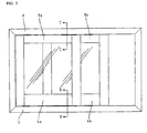
- FIG. 1 is a front view showing a window or door to which a related art window or door system is applied.
- FIG. 2 is a sectional view taken along line A-A of FIG. 1 .
- the related art window or door system includes a window frame lower member 1 and window leaf lower members 2a and 2b.
- the window frame lower member 1 is provided with exposed rails 11 and 11.
- the window leaf lower members 2a and 2b are provided with rollers 21 and 21 mounted and arranged on the rails 11, and are guided by mohair members 22,22,22, and 22 and the rails 11 and 11 to open and close.
- the window leaf is inserted into the window frame, it is simple to assembly and disassembly the window leaf. However, it is likely that the window leaf is detached due to strong wind or manipulation. Accordingly, when the window leaf is used in a multistoried building, the window leaf is likely to be fallen down by being detached from the window frame. This causes dangerous situations.
- FR-A-2 653 817 discloses a sliding window or door system with a rail that is covered by flexible seals.
- US-A- 2151033 discloses a sliding window or door system with a compressable rubberstrip inserted in the rail.
- the present invention is directed to a sliding window or door system that substantially obviates one or more of the problems due to limitations and disadvantages of the related art.
- An object of the present invention is to provide a sliding window or door system of filling a rail having an even structure to remarkably improve air tightness, water tightness, and thermal insulation.
- Another object of the present invention is to provide a sliding window or door system, which is likely to maintain a cleaning state and prevents a window leaf from being detached, thereby ensuring stability.
- Another object of the present invention is to provide a sliding window or door system, which is likely to improve appearance depending on taste and functions, thereby providing high quality.
- a sliding window or door system includes: a window or door frame lower member having a a window or door frame base member provided with surface members, rail device grooves and rail devices for inserting into the rail device grooves, the rail devices each including a rail device base member corresponding to the rail device grooves an elastic member, a rail filling member, and roller supporting members, thereby forming an even structure window or door leaf lower members for driving height control rollers provided with projections to correspond to the rail systems by inserting the height control rollers into roller grooves formed in window or door leaf base members to be guided by the projections and the rail devices, and for mounting gaskets to maintain air tightness between the window leaf base members and the surface members; a window or door frame upper member having a window or door frame base member similar to the window or door frame base member of the window or door frame lower member, except that the rail device grooves correspond to supporting grooves to which upper insertion portions of window or
- FIG. 3 is a front view showing a window or door viewed from an outside, to which a window or door system according to the present invention is applied. Sectional views taken along lines B-B and C-C are shown in FIGS. 4 , 6 , 7 , 8 , 10 , and 11 .
- FIGS. 4 , 6 , and 7 are sectional views taken along line B-B of FIG. 3 , in which main elements of a sliding window or door system are shown.
- a window frame lower member 3 includes a window frame base member 31, surface members 32, 32, and 32, rail device grooves 33 and 33, and rail devices 38 and 38.
- the rail device grooves 33 and 33 for installation of the rail devices 38 and 38 and the surface members 32, 32, and 32 are provided in the window frame base member 31.
- the rail device 38 having a rail device base member 34 corresponding to the rail device grooves 33 and 33, an elastic member 35, a rail filling member 36, and roller supporting members 37 are inserted into the rail device grooves 33 and 33 provided in the window frame base member 31.
- An even structure of the window frame lower member 3 is constructed as above (see a schematic view of the rail system of FIG. 5 ).
- window leaf lower members 4a and 4b The construction of window leaf lower members 4a and 4b will now be described.
- Height control rollers 42 and 42 provided with projections 41 and 41 to correspond to the rail devices 38 and 38 are inserted into roller grooves 44 and 44 provided in window leaf base members 43 and 43, so that the rollers 42 and 42 are guided and driven by the projections 41 and 41 and the rail devices 38 and 38.
- gaskets 45,45,45 and 45 are mounted.
- the window leaf lower members 4a and 4b can correspond to the window frame lower member 3.
- the projections 41 and 41 of the rollers 42 and 42 push the rail filling member 36 of the rail devices 38 and 38 and compress the elastic member 35.
- the projections are inserted into the grooves provided between the roller supporting members 37.
- the rollers 42 and 42 are guided to the grooves between the roller supporting members 37 and then driven. If the rollers 42 and 42 are driven, the compressed elastic member 35 is returned to its original state and the rail filling member 36 fills the grooves between the roller supporting members 37 to form an even surface.
- window frame lower members 5 and 6 include surface members 52, 52,52,62,62, and 62 provided in window frame base members 51 and 61 in a frame type. In this case, rainwater is smoothly guided to the outside.
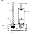
- FIGS. 8 , 10 , and 11 are sectional views taken along line C-C of FIG. 3 , in which main elements of a sliding window or door system are shown.
- a window frame base member 81 of a window frame upper member 8 is similar to the window frame base member 31 of the window frame lower member, but is mounted in an upper side of the window or door system.
- the rail device grooves 33 and 33 correspond to supporting grooves 82 and 82, to which upper insertion portions 91 and 91 of window leaf upper members 9a and 9b are inserted.
- the window leaf upper members 9a and 9b include the upper insertion portions 91 and 91 to correspond to the window frame upper member 8.
- Control rollers 93 and 93 for preventing the window leaf from being detached by cutting a cutting portion 92 of the upper insertion portions 91 and 91 are mounted in the window leaf upper members 9a and 9b (see installation view of FIG. 9 ).
- the height of the control rollers 93 and 93 is downwardly controlled.
- the upper insertion portions 91 and 91 are deeply inserted into the supporting grooves 82 and 82 to facilitate installation of the lower member.
- an inner space formed between the upper insertion portions 91 and 91 and the supporting grooves 82 and 82 is finished up by upwardly controlling the height of the control rollers 93 and 93.
- FIG. 8 shows an installation state, in which the window leaf upper members 9a and 9b cannot be detached due to the control rollers 93 and 93.
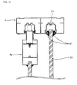
- the even structure can be constructed in a frame type structure.
- window frame upper members 10 and 20 of a frame type structure and window leaf upper members 30a and 30b are shown.
- the height of the window leaf upper members 30a and 30b is controlled to correspond to the window frame upper members 10 and 20.
- FIG. 12 is a front view showing a window or door viewed from an outside, in which an outdoor window leaf is replaced with a fixed window.
- FIGS. 13 and 14 are sectional views taken along lines D-D and E-E of FIG. 12 .
- the window leaf lower member 3 is replaced with an outdoor window leaf 4a in such a manner that a fixed window 40 is mounted into an outdoor rail device groove 39, and finished up with a gasket 401 and a supporting member 402.
- a window frame upper member 8 is replaced with an outdoor window leaf 9a in such a manner that a fixed window 40 is mounted into an indoor supporting groove 83 and finished up with a gasket 401.
- FIG. 15 is a front view showing a window or door viewed from an outside, in which an indoor window leaf is replaced with a fixed window.
- FIGS. 16 and 17 are sectional views taken along lines F-F and G-G of FIG. 15 .
- the window leaf lower member 3 is replaced with an indoor window leaf 4b in such a manner that a fixed window 50 is mounted into an indoor rail device groove 3a and finished up with gaskets 501 and 501 and a supporting member 502.
- a window frame upper member 8 is replaced with an indoor window leaf 9b in such a manner that a fixed window 50 is mounted into an indoor supporting groove 84 and finished up with gaskets 501 and 501.
- FIG. 18 a groove 60 in a portion having no fixed windows 40 and 50 in FIGS. 13 , 14 , 16 and 17 is finished up with a fixed window groove cover 70.
- the sliding window or door system according to the present invention has the following advantages.
- a drainage outlet is provided in a rail to drain out rainwater because the rail is exposed.
- rainwater is guided to the outside on the surface. Accordingly, the rainwater is essentially prevented from being induced into the indoor. Also, since no separate drainage outlet is provided, air tightness, water tightness, and thermal insulation can be improved. Since the process steps can be reduced, the productivity can be improved.
- a detachment prevention structure is applied, so that vertical movement of the window leaf in the upper and lower directions can be avoided. Accordingly, safety can be ensured by solving the problem related to detachment due to strong wind or manipulation.
- the related art window or door system has a problem in that movement and noise of the window leaf occur and a window frame should be exchanged with another one if the rail is abraded.
- a rail system is only to be exchanged with another one if the rail is abraded. Accordingly, the production cost and time can be reduced.
Landscapes
- Engineering & Computer Science (AREA)
- Civil Engineering (AREA)
- Structural Engineering (AREA)
- Mechanical Engineering (AREA)
- Support Devices For Sliding Doors (AREA)
- Specific Sealing Or Ventilating Devices For Doors And Windows (AREA)
- Wing Frames And Configurations (AREA)
- Door And Window Frames Mounted To Openings (AREA)
- Hinge Accessories (AREA)
Claims (3)
- Système de fenêtre ou de porte coulissante comprenant :un élément inférieur de cadre de fenêtre ou de porte (3) ayant un élément de base de cadre de fenêtre ou de porte (31) pourvu d'éléments de surface (32, 32, 32), des rainures pour dispositif à rail (33, 33), et des dispositifs à rail (38, 38) destinés à être insérés dans les rainures pour dispositif à rail (33, 33), les dispositifs à rail (38, 38) comprenant chacun un élément de base de dispositif à rail (34) correspondant aux rainures pour dispositif à rail (33, 33), des éléments de support à galets (37, 37), un élément élastique (35) et un élément de remplissage de rail (36), formant ainsi une structure plane ;des éléments inférieurs de panneaux de fenêtres ou de portes (4a, 4b) ayant des éléments de base de panneaux de fenêtres de portes (43, 43) pour entraîner des galets de commande de hauteur (42, 42) dotés de projections (41, 41) pour correspondre aux dispositifs à rail (38, 38) en insérant les galets de commande de hauteur (42, 42) dans des rainures à galets (44, 44) formées dans les éléments de base de panneaux de fenêtres ou de portes (43, 43) et pour monter des joints (45, 45, 45, 45) afin de maintenir l'étanchéité à l'air entre les éléments de base de panneaux de fenêtres ou de portes (43, 43) et les éléments de surface (32, 32, 32) ;dans lequel les éléments inférieurs de panneaux de fenêtres ou de portes (4a, 4b) sont guidés par les projections (41, 41) en poussant l'élément de remplissage de rail (36) et en comprimant l'élément élastique (35) afin de réaliser des rainures entre les éléments de support de galets (37, 37) pour insérer les projections (41, 41) dans celles-ci ;un élément supérieur de cadre de fenêtre ou de porte (8) ayant un élément de base de cadre de fenêtre ou de porte (81) similaire à l'élément de base de cadre de fenêtre ou de porte (31) de l'élément inférieur de cadre de fenêtre ou de porte (3), à l'exception que des rainures pour dispositif à rail (33, 33) correspondent aux rainures de support (82, 82) dans lesquelles sont insérées des portions d'insertion supérieures (91, 91) des éléments supérieurs de panneaux de fenêtres ou de portes (9a, 9b) ; etles éléments supérieurs de panneaux de fenêtres ou de portes (9a, 9b) dotés de galets de commande (93, 93) montés dans les portions d'insertion supérieures (91, 91) pour empêcher que le panneau de fenêtre se détache.
- Système de fenêtre ou de porte coulissante selon la revendication 1, comprenant en outre :des éléments inférieurs de cadres de fenêtres ou de portes (5, 6) dotés d'éléments de surface (52, 52, 52, 62, 62, 62) dans un type de cadre ;des éléments inférieurs de panneaux de fenêtres ou de portes (7a, 7b) dont la hauteur est commandée pour correspondre aux éléments inférieurs de cadres de fenêtres (5, 6) ;des éléments supérieurs de cadres de fenêtres ou de portes (10, 20) dotés d'éléments de surface (102, 102, 102, 202, 202, 202) formés dans un type de cadre ; etdes éléments supérieurs de panneaux de fenêtres ou de portes (30a, 30b) ayant une hauteur commandée de manière à correspondre aux éléments supérieurs de cadres de fenêtres ou de portes (10, 20), formant ainsi une structure du type cadre.
- Système de fenêtre ou de porte coulissante selon la revendication 1 ou 2, dans lequel les panneaux de fenêtres ou de portes (4a, 7a, 9a, 30a) depuis l'extérieur ou bien les panneaux de fenêtres ou de portes (4b, 7b, 9b, 30b) depuis l'intérieur sont remplacés avec des fenêtres ou des portes fixes (40, 50) et terminés au moyen de joints (401, 401, 501, 501), et une gorge (60) dans une portion dans laquelle les fenêtres ou les portes fixes ne sont pas montées est terminée avec une couverture de rainure de fenêtre ou de porte fixe (70).
Applications Claiming Priority (3)
| Application Number | Priority Date | Filing Date | Title |
|---|---|---|---|
| KR1019990038490A KR100324496B1 (ko) | 1999-09-10 | 1999-09-10 | 레일채움형 창호장치 |
| KR9938490 | 1999-09-10 | ||
| PCT/KR2000/001026 WO2001020115A1 (fr) | 1999-09-10 | 2000-09-08 | Systeme de fenetre/porte coulissante destine au remplissage d'un rail |
Publications (3)
| Publication Number | Publication Date |
|---|---|
| EP1214493A1 EP1214493A1 (fr) | 2002-06-19 |
| EP1214493A4 EP1214493A4 (fr) | 2008-10-29 |
| EP1214493B1 true EP1214493B1 (fr) | 2011-11-16 |
Family
ID=19610853
Family Applications (1)
| Application Number | Title | Priority Date | Filing Date |
|---|---|---|---|
| EP00959022A Expired - Lifetime EP1214493B1 (fr) | 1999-09-10 | 2000-09-08 | Systeme de fenetre ou porte coulissante |
Country Status (8)
| Country | Link |
|---|---|
| US (1) | US6901705B1 (fr) |
| EP (1) | EP1214493B1 (fr) |
| JP (1) | JP4472908B2 (fr) |
| KR (1) | KR100324496B1 (fr) |
| CN (1) | CN1154783C (fr) |
| AU (1) | AU7041200A (fr) |
| HK (1) | HK1049869B (fr) |
| WO (1) | WO2001020115A1 (fr) |
Families Citing this family (30)
| Publication number | Priority date | Publication date | Assignee | Title |
|---|---|---|---|---|
| KR20000058616A (ko) * | 2000-06-20 | 2000-10-05 | 구현석 | 레일이 보이지 않는 창틀 |
| KR20020060121A (ko) * | 2002-05-30 | 2002-07-16 | 최성준 | 미닫이 창틀의 창틀 끼임 방지와 청소의 용이. |
| US20090100760A1 (en) * | 2004-04-22 | 2009-04-23 | Ewing K Bradley | Snap fit hanging panel and locking apparatus therefore |
| CN1858391B (zh) * | 2006-05-23 | 2011-06-22 | 赖世帽 | 一种带活动上滑道的推拉门窗 |
| US10487567B1 (en) * | 2007-06-28 | 2019-11-26 | Almon Blair | Apparatus and method for installing glass |
| IL184860A (en) * | 2007-07-26 | 2012-04-30 | Amos Halfon | Automatic coupling mechanism for sliding doors of a storage unit |
| KR101180620B1 (ko) | 2010-10-08 | 2012-09-06 | 이건산업 주식회사 | 슬라이딩 도어용 트랙구조 |
| KR101070300B1 (ko) | 2011-06-17 | 2011-10-07 | (주)메탈프린스 | 붙박이장의 외측도어용 롤러 이탈 방지장치 |
| KR101068926B1 (ko) | 2011-06-17 | 2011-10-04 | (주)메탈프린스 | 붙박이장의 내측도어용 롤러 이탈 방지장치 |
| CN102536022A (zh) * | 2012-01-07 | 2012-07-04 | 潘锡波 | 一种应用在下承重门窗上的保险结构 |
| CN102777095A (zh) * | 2012-07-27 | 2012-11-14 | 南京康尼机电股份有限公司 | 带式下导轨装置 |
| CN102996027A (zh) * | 2012-12-27 | 2013-03-27 | 江苏银奕达铝业有限公司 | 一种低成本推拉窗 |
| KR101467244B1 (ko) * | 2012-12-31 | 2014-12-10 | 손동열 | 건물 외측 여닫이 및 미닫이 겸용 창호 |
| DE102013111482B4 (de) * | 2013-10-17 | 2026-01-22 | Hettich-Heinze Gmbh & Co. Kg | Führungseinrichtung für eine Schiebetür |
| KR101466870B1 (ko) * | 2013-10-25 | 2014-12-03 | 김순석 | 구조변경이 용이한 평레일 창호장치 |
| KR101387318B1 (ko) | 2013-11-05 | 2014-04-18 | 김순석 | 이형프레임 구조를 갖는 복합창호장치 조립구조 |
| KR101446899B1 (ko) | 2014-02-25 | 2014-10-06 | 김순석 | ㄷ자 형상의 롤러지지대를 구비한 평레일 창호장치 |
| CN104695811B (zh) * | 2015-03-12 | 2016-08-24 | 嘉寓门窗幕墙(临邑)有限公司 | 推拉门窗的框架型材、导轨、密封条、锁头、框架条、框架 |
| JP6576238B2 (ja) * | 2015-12-25 | 2019-09-18 | Ykk Ap株式会社 | 浴室用建具 |
| CN106437379A (zh) * | 2016-12-03 | 2017-02-22 | 江苏宇马铝业有限公司 | 一种铝合金推拉门分体式导轨结构 |
| CN106761214A (zh) * | 2017-01-04 | 2017-05-31 | 中国建材国际工程集团有限公司 | 推拉窗 |
| GR1009233B (el) * | 2017-01-13 | 2018-02-22 | ORAMA MINIMAL FRAMES EΤΑΙΡΕΙΑ ΠΕΡΙΟΡΙΣΜΕΝΗΣ ΕΥΘΥΝΗΣ με δτ ORAMA MINIMAL FRAMES E.Π.Ε | Ημι-αορατος συνδυασμος θερμομονωτικων διατομων για ανεμποδιστη διελευση του κατω μερους συρομενου πορτοπαραθυρου |
| US10801240B2 (en) * | 2017-06-30 | 2020-10-13 | Fleetwood Aluminum Products, Inc. | Flush to floor sill track and assembly for sliding glass windows |
| KR101894436B1 (ko) * | 2017-09-26 | 2018-09-04 | 김성환 | 창틀 레일홈 은닉용 승강패널 |
| KR102092632B1 (ko) * | 2018-06-14 | 2020-03-24 | 정준호 | 슬라이딩 도어시스템의 문틀용 하부프레임 |
| KR20200049987A (ko) | 2018-10-30 | 2020-05-11 | 주식회사 두테크 | 슬라이딩 도어용 하부레일 |
| KR102104749B1 (ko) | 2019-05-27 | 2020-04-24 | 한범수 | 창호 보강블럭 및 이를 이용한 창호 조립 방법 |
| WO2020264085A1 (fr) * | 2019-06-28 | 2020-12-30 | Glazcon Production, Inc. | Système de panneau pour portes ou panneaux coulissants |
| CN111301119B (zh) * | 2020-03-03 | 2022-02-18 | 福耀玻璃工业集团股份有限公司 | 一种滑动窗总成 |
| KR102610992B1 (ko) | 2022-11-02 | 2023-12-07 | 주식회사 피에이글로벌 | 기능성 창호 |
Family Cites Families (29)
| Publication number | Priority date | Publication date | Assignee | Title |
|---|---|---|---|---|
| US2151033A (en) * | 1939-03-21 | Folding partition | ||
| US134698A (en) * | 1873-01-07 | Improvement in guides for elevators | ||
| US2078811A (en) * | 1935-03-06 | 1937-04-27 | Silent Gliding Doors Ltd | Guide rail for rollers, wheels, and the like |
| BE613405A (fr) * | 1961-02-07 | 1962-05-29 | Aluco Ag | Construction de fenêtre à vitrage double ou multiple |
| US3436864A (en) * | 1966-05-04 | 1969-04-08 | Williamsburg Steel Products Co | Door support and guidance mechanism |
| US3785090A (en) * | 1972-03-20 | 1974-01-15 | D Macgillis | Metal window construction with clamped corner joints |
| US3810330A (en) * | 1972-09-05 | 1974-05-14 | American Standard Inc | Movable panel system |
| US3855732A (en) * | 1973-10-15 | 1974-12-24 | Rollyson Aluminum Prod | Threshold strip for sliding doors having replaceable bearing track |
| NL7514636A (nl) * | 1974-12-25 | 1976-06-29 | Yoshida Kogyo Kk | Venstereenheid met een hulpdorpelplaat. |
| US4051633A (en) * | 1976-06-01 | 1977-10-04 | Voegele Jr William P | Top hung sliding window assembly |
| US4398373A (en) * | 1980-11-28 | 1983-08-16 | Fiberlux Products, Inc. | Vinyl frame, multi-panel, sliding door assembly |
| JPS5831375U (ja) * | 1981-08-25 | 1983-03-01 | 積水化学工業株式会社 | 二重サッシ |
| US4633616A (en) * | 1984-07-05 | 1987-01-06 | Donat Flamand Inc. | Patio-door unit |
| US4868935A (en) * | 1985-04-05 | 1989-09-26 | Sterling Plumbing Group, Inc. | Movable glide support for tub enclosure and shower stall doors |
| US4599836A (en) * | 1985-06-20 | 1986-07-15 | Randy Melcher | Self-storing window assembly |
| DE3606501A1 (de) * | 1986-02-28 | 1987-09-03 | Juergen Guddas | Vorrichtung zum fixieren der offenstellungen und/oder schliessstellungen von schiebefluegeln |
| US4800619A (en) * | 1987-07-31 | 1989-01-31 | Douglas & Lomason Company | Wear insert for a door channel |
| FR2653817B1 (fr) * | 1989-10-27 | 1992-02-07 | Krieg & Zivy | Rail bas pour porte coulissante, notamment pour placard. |
| US5222541A (en) * | 1992-07-22 | 1993-06-29 | Kelley Company, Inc. | Industrial door having releasable beam and tension bracket retention mechanism |
| KR960009673Y1 (ko) * | 1993-05-07 | 1996-10-31 | 주식회사 주일 | 레일이 탈부착가능한 압출성형식 창 · 문틀 |
| US5488803A (en) * | 1994-10-03 | 1996-02-06 | Premier Window & Door, Inc. | Sash insert for sliding door |
| US5884361A (en) * | 1994-10-06 | 1999-03-23 | Anthony's Manufacturing Company | Slider door mechanism, running gear mechanism and closure return |
| DE4435641C2 (de) * | 1994-10-06 | 1998-12-03 | Juergen Guddas | Schiebeflügel zum bedarfsweisen Verschließen, insbesondere einer offenen Seite von Balkonen, Wintergärten u. dgl. |
| JP2832802B2 (ja) * | 1994-12-21 | 1998-12-09 | ワイケイケイアーキテクチュラルプロダクツ株式会社 | 窓 枠 |
| KR960038040U (ko) * | 1995-05-25 | 1996-12-18 | 컨벡션 오븐조리기능을 갖는 로터리 히터 | |
| US5836111A (en) * | 1996-04-16 | 1998-11-17 | Fine Industries, Inc. | Opening-closing device for windows |
| FR2756587B1 (fr) * | 1996-12-03 | 1999-01-15 | Ferco Int Usine Ferrures | Dispositif de roulement pour ouvrant coulissant |
| KR200151667Y1 (ko) * | 1997-06-04 | 1999-07-15 | 한창훈 | 창틀의 바닥구성용 수평바아의 구조 |
| US5927017A (en) * | 1998-01-30 | 1999-07-27 | The Stanley Works | Sliding door bottom roller assembly with a rotatable anti-jump member |
-
1999
- 1999-09-10 KR KR1019990038490A patent/KR100324496B1/ko not_active Expired - Lifetime
-
2000
- 2000-09-08 HK HK03101893.3A patent/HK1049869B/zh not_active IP Right Cessation
- 2000-09-08 AU AU70412/00A patent/AU7041200A/en not_active Abandoned
- 2000-09-08 EP EP00959022A patent/EP1214493B1/fr not_active Expired - Lifetime
- 2000-09-08 CN CNB008137935A patent/CN1154783C/zh not_active Expired - Fee Related
- 2000-09-08 US US10/070,980 patent/US6901705B1/en not_active Expired - Fee Related
- 2000-09-08 JP JP2001523473A patent/JP4472908B2/ja not_active Expired - Fee Related
- 2000-09-08 WO PCT/KR2000/001026 patent/WO2001020115A1/fr not_active Ceased
Also Published As
| Publication number | Publication date |
|---|---|
| CN1154783C (zh) | 2004-06-23 |
| WO2001020115A1 (fr) | 2001-03-22 |
| KR20010026968A (ko) | 2001-04-06 |
| KR100324496B1 (ko) | 2002-02-27 |
| JP2003509608A (ja) | 2003-03-11 |
| JP4472908B2 (ja) | 2010-06-02 |
| AU7041200A (en) | 2001-04-17 |
| US6901705B1 (en) | 2005-06-07 |
| EP1214493A4 (fr) | 2008-10-29 |
| HK1049869A1 (en) | 2003-05-30 |
| CN1377439A (zh) | 2002-10-30 |
| EP1214493A1 (fr) | 2002-06-19 |
| HK1049869B (zh) | 2005-03-18 |
Similar Documents
| Publication | Publication Date | Title |
|---|---|---|
| EP1214493B1 (fr) | Systeme de fenetre ou porte coulissante | |
| US4554770A (en) | Horizontal sliding window with removable fixed sash | |
| EP3859120B1 (fr) | Un dispositif d'écran pour une fenêtre de toit, une fenêtre de toit comprenant un tel dispositif d'écran, et un procédé d'installation d'un dispositif d'écran dans une fenêtre de toit | |
| EP1222353B1 (fr) | Systeme de fenetre et de porte sans rail | |
| CN102606036A (zh) | 多功能推拉门窗 | |
| CN202611454U (zh) | 一种多功能推拉门窗 | |
| CN215563922U (zh) | 高热厂房用屋面通风天窗结构 | |
| KR20200137415A (ko) | 창호용 틈새 방지구 | |
| KR20190071306A (ko) | 창호 시스템 | |
| KR200309088Y1 (ko) | 창문의 기밀 구조 | |
| CN220059369U (zh) | 一种窗户排水结构 | |
| JP3232267B2 (ja) | 改装サッシ | |
| CN215520573U (zh) | 一种推拉门窗 | |
| CN217461891U (zh) | 一种滑动推拉窗结构 | |
| KR200186904Y1 (ko) | 방풍용 창문틀 구조 | |
| CN213175296U (zh) | 高水密性内置隐纱平开窗 | |
| KR102457522B1 (ko) | 창호가 구비된 커튼월구조 | |
| CN213418871U (zh) | 一种防止铝合金推拉门窗外坠结构 | |
| JPS6220633Y2 (fr) | ||
| KR200196848Y1 (ko) | 환기창이 설치된 현관문 | |
| CN2430527Y (zh) | 门窗排水孔盖 | |
| JPH0118794Y2 (fr) | ||
| JPS634111Y2 (fr) | ||
| CN211370064U (zh) | 一种高低轨的窗扇结构 | |
| JPS6017500Y2 (ja) | 二重窓の窓枠構造 |
Legal Events
| Date | Code | Title | Description |
|---|---|---|---|
| PUAI | Public reference made under article 153(3) epc to a published international application that has entered the european phase |
Free format text: ORIGINAL CODE: 0009012 |
|
| 17P | Request for examination filed |
Effective date: 20020308 |
|
| AK | Designated contracting states |
Kind code of ref document: A1 Designated state(s): AT BE CH CY DE DK ES FI FR GB GR IE IT LI LU MC NL PT SE |
|
| AX | Request for extension of the european patent |
Free format text: AL;LT;LV;MK;RO;SI |
|
| RBV | Designated contracting states (corrected) |
Designated state(s): DE ES FR GB IT NL |
|
| A4 | Supplementary search report drawn up and despatched |
Effective date: 20081001 |
|
| RIC1 | Information provided on ipc code assigned before grant |
Ipc: E06B 3/46 20060101AFI20080925BHEP Ipc: E05D 15/06 20060101ALI20080925BHEP |
|
| 17Q | First examination report despatched |
Effective date: 20090812 |
|
| RTI1 | Title (correction) |
Free format text: SLIDING WINDOW OR DOOR SYSTEM |
|
| GRAP | Despatch of communication of intention to grant a patent |
Free format text: ORIGINAL CODE: EPIDOSNIGR1 |
|
| GRAS | Grant fee paid |
Free format text: ORIGINAL CODE: EPIDOSNIGR3 |
|
| GRAA | (expected) grant |
Free format text: ORIGINAL CODE: 0009210 |
|
| AK | Designated contracting states |
Kind code of ref document: B1 Designated state(s): DE ES FR GB IT NL |
|
| REG | Reference to a national code |
Ref country code: GB Ref legal event code: FG4D |
|
| REG | Reference to a national code |
Ref country code: DE Ref legal event code: R096 Ref document number: 60046670 Country of ref document: DE Effective date: 20120209 |
|
| REG | Reference to a national code |
Ref country code: NL Ref legal event code: T3 |
|
| PG25 | Lapsed in a contracting state [announced via postgrant information from national office to epo] |
Ref country code: IT Free format text: LAPSE BECAUSE OF FAILURE TO SUBMIT A TRANSLATION OF THE DESCRIPTION OR TO PAY THE FEE WITHIN THE PRESCRIBED TIME-LIMIT Effective date: 20111116 |
|
| PLBE | No opposition filed within time limit |
Free format text: ORIGINAL CODE: 0009261 |
|
| STAA | Information on the status of an ep patent application or granted ep patent |
Free format text: STATUS: NO OPPOSITION FILED WITHIN TIME LIMIT |
|
| 26N | No opposition filed |
Effective date: 20120817 |
|
| REG | Reference to a national code |
Ref country code: DE Ref legal event code: R097 Ref document number: 60046670 Country of ref document: DE Effective date: 20120817 |
|
| PGFP | Annual fee paid to national office [announced via postgrant information from national office to epo] |
Ref country code: FR Payment date: 20120926 Year of fee payment: 13 |
|
| PGFP | Annual fee paid to national office [announced via postgrant information from national office to epo] |
Ref country code: NL Payment date: 20120908 Year of fee payment: 13 |
|
| PG25 | Lapsed in a contracting state [announced via postgrant information from national office to epo] |
Ref country code: ES Free format text: LAPSE BECAUSE OF FAILURE TO SUBMIT A TRANSLATION OF THE DESCRIPTION OR TO PAY THE FEE WITHIN THE PRESCRIBED TIME-LIMIT Effective date: 20120227 |
|
| PGFP | Annual fee paid to national office [announced via postgrant information from national office to epo] |
Ref country code: DE Payment date: 20130904 Year of fee payment: 14 |
|
| PGFP | Annual fee paid to national office [announced via postgrant information from national office to epo] |
Ref country code: GB Payment date: 20130904 Year of fee payment: 14 |
|
| REG | Reference to a national code |
Ref country code: NL Ref legal event code: V1 Effective date: 20140401 |
|
| REG | Reference to a national code |
Ref country code: FR Ref legal event code: ST Effective date: 20140530 |
|
| PG25 | Lapsed in a contracting state [announced via postgrant information from national office to epo] |
Ref country code: NL Free format text: LAPSE BECAUSE OF NON-PAYMENT OF DUE FEES Effective date: 20140401 Ref country code: FR Free format text: LAPSE BECAUSE OF NON-PAYMENT OF DUE FEES Effective date: 20130930 |
|
| REG | Reference to a national code |
Ref country code: DE Ref legal event code: R119 Ref document number: 60046670 Country of ref document: DE |
|
| GBPC | Gb: european patent ceased through non-payment of renewal fee |
Effective date: 20140908 |
|
| PG25 | Lapsed in a contracting state [announced via postgrant information from national office to epo] |
Ref country code: DE Free format text: LAPSE BECAUSE OF NON-PAYMENT OF DUE FEES Effective date: 20150401 Ref country code: GB Free format text: LAPSE BECAUSE OF NON-PAYMENT OF DUE FEES Effective date: 20140908 |