EP1214873A1 - Dispositif d'introduction pour moissonneuse à écoulement axial - Google Patents
Dispositif d'introduction pour moissonneuse à écoulement axial Download PDFInfo
- Publication number
- EP1214873A1 EP1214873A1 EP01128206A EP01128206A EP1214873A1 EP 1214873 A1 EP1214873 A1 EP 1214873A1 EP 01128206 A EP01128206 A EP 01128206A EP 01128206 A EP01128206 A EP 01128206A EP 1214873 A1 EP1214873 A1 EP 1214873A1
- Authority
- EP
- European Patent Office
- Prior art keywords
- self
- harvesting machine
- machine according
- rotor
- propelled harvesting
- Prior art date
- Legal status (The legal status is an assumption and is not a legal conclusion. Google has not performed a legal analysis and makes no representation as to the accuracy of the status listed.)
- Granted
Links
- 238000003306 harvesting Methods 0.000 claims description 21
- 238000005461 lubrication Methods 0.000 claims description 6
- 230000002787 reinforcement Effects 0.000 claims description 4
- 230000003014 reinforcing effect Effects 0.000 claims 2
- 239000000463 material Substances 0.000 description 9
- 238000000926 separation method Methods 0.000 description 5
- 241001124569 Lycaenidae Species 0.000 description 3
- 238000000034 method Methods 0.000 description 3
- 239000000203 mixture Substances 0.000 description 3
- 238000009826 distribution Methods 0.000 description 2
- 230000000694 effects Effects 0.000 description 2
- 239000000314 lubricant Substances 0.000 description 2
- 238000003860 storage Methods 0.000 description 2
- 238000011144 upstream manufacturing Methods 0.000 description 2
- TVEXGJYMHHTVKP-UHFFFAOYSA-N 6-oxabicyclo[3.2.1]oct-3-en-7-one Chemical compound C1C2C(=O)OC1C=CC2 TVEXGJYMHHTVKP-UHFFFAOYSA-N 0.000 description 1
- 238000009825 accumulation Methods 0.000 description 1
- 230000000903 blocking effect Effects 0.000 description 1
- 238000005520 cutting process Methods 0.000 description 1
- 230000002349 favourable effect Effects 0.000 description 1
- 238000003780 insertion Methods 0.000 description 1
- 230000037431 insertion Effects 0.000 description 1
- 230000001050 lubricating effect Effects 0.000 description 1
- 239000002184 metal Substances 0.000 description 1
- 238000005192 partition Methods 0.000 description 1
- 230000000149 penetrating effect Effects 0.000 description 1
- 230000008092 positive effect Effects 0.000 description 1
- 239000010902 straw Substances 0.000 description 1
- 238000010408 sweeping Methods 0.000 description 1
Images

Classifications
-
- A—HUMAN NECESSITIES
- A01—AGRICULTURE; FORESTRY; ANIMAL HUSBANDRY; HUNTING; TRAPPING; FISHING
- A01F—PROCESSING OF HARVESTED PRODUCE; HAY OR STRAW PRESSES; DEVICES FOR STORING AGRICULTURAL OR HORTICULTURAL PRODUCE
- A01F12/00—Parts or details of threshing apparatus
- A01F12/10—Feeders
Definitions
- the invention relates to a self-propelled harvesting machine according to the preamble of the claim 1.
- Such agricultural harvesters designed as combine harvesters can both according to the pure axial process or the mixed system, with the tangential threshing unit combined with axially acting separators, work.
- Combine harvesters designed in this way are usually in parallel with one or more side by side, with inner guide strips, at least in some areas as Screen or perforated surface trained rotor housings, each of these housings receives a separating rotor, the front end for the acceptance of goods with screw sections is equipped, and arranged on the outer jacket conveyor elements are that in cooperation with the guide rails attached in the rotor housing Harvest mixture of grain, straw and chaff between the separating rotor and the housing for the rear Transport the end of the separating rotor, in particular the grains from the mixture be eliminated.
- the axis of such separating rotors is supported in at the material inlet end one that partially closes the cross section of the housing, extends over the central axis of the Rotor housing, downward extending end wall, the lower edge of the remaining Good inlet opening limited at the top.
- German patent DE 24 30 304 runs with such threshing and / or Separators the bottom edge of the bulkhead horizontally from one side to the other of the cylindrical rotor housing.
- the separating rotor is mounted in the rotor housing in such a way that the Conveyor vanes of the conveyor screw sections protrude into the material inlet opening and with their Stand the front edges close to the inner surface of the front wall.
- the object of the invention is therefore to eliminate the disturbances known from the prior art avoid.
- At least one separating rotor can at least have a further one Partially surrounded by a separating rotor to be attached to his end pointing in the direction of travel also by means of a bearing in one with the inventive lower edge provided further side wall is stored.
- the lower edges of the end walls can be reached also be arched. This ensures that there is a gap between these lower edges of the end walls and the driving elements of the separating rotors Harvest crop located in the radial direction of the separating rotor from this forming Feed gap can be brought out.
- the crop acceptance is always positively influenced when the lower edges the end walls are arranged offset from each other and that of the direction of rotation of the respective Separating rotor opposite lower edge of the respective end wall in the vertical direction is more engaged.
- the lower edges of the end walls can also be hollow profile be inside and have lubrication channels that reduce wear on the bearings Lubricants can be supplied.
- the end walls can be on the inside Wiper strips can be assigned, which remove the crop from the catchment area support of the respective separating rotor, whereby the good discharge process thereby can still be forced that the squeegees in the direction of rotation of the respective separating rotor are curved.
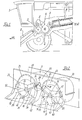
- the front part of a self-propelled combine is designated, which in known Has an inclined conveyor 2, of which the crop via a pre-accelerator 3rd the threshing mechanism 6 formed from the concave 4 and threshing drum 5 is fed.
- the Threshed crop material emerging from the threshing unit 6 is then transferred to a transfer drum 7 one of two rotor housings arranged parallel to one another in the direction of travel FR 9 and 10 existing axial separation device 8 supplied.
- the rotor housings are in on associated with guide rails, which are known and therefore not shown in detail, on the inside, the transport of the crop strand in the rear area of the axial separating device 8 support.
- the bearings 15, 16 receiving hood-shaped end walls 21, 22 are in their rear Detachable area at a boundary delimiting the material inlet area from the separating rotors 11, 12 Front plate 23 attached, the front plate 23 underside the diameter of the upstream Transfer drum 7 is adapted and in its rear area of the front ends of the rotor housing 9, 10 is added.
- the lower edges 17-20 of the end walls 21, 22 are in the region of the lower edges 17-20 reinforcement profiles 24-27 welded onto the end walls 21, 22. In the simplest and therefore not shown in detail, these stiffening profiles 24-27 of thick-walled Formed metal plates.
- the lower edges 17-20 of the end walls 21, 22 are in accordance with the invention Executed in such a way that they deviate from the horizontal Position along the bottom end of the end walls 21, 22 extend. It's in the frame of the invention that even one of the lower edges 17-20 deviates from the horizontal Takes up position to ensure a trouble-free intake of the crop.
- the lower edges 17-20 shown in FIG. 3 can also be arcuate, the Curvature of these curved lower edges 17-20 in the vertical direction extends upwards. It would also differ from the exemplary embodiment shown conceivably only one of the lower edges 17-20, namely that opposite to the direction of rotation 30, 31 lower edge 18, 19 to perform an arc to pinch the described Avoid crops during the feeding process.
- the transfer drum 7 in a known and therefore not shown Way approximately centrally separated crop flow to the separating rotors 11, 12 in the Area of the front panel 23 can be transferred and is quickly removed from this, are the separating rotors with their in a further advantageous embodiment of the invention front walls 21, 22 according to the invention arranged in mirror image to one another arranged, the ones forming the inlet area being steeper in the vertical direction lower edges 18, 19 facing each other and the separating rotors 11, 12 with opposite Rotate in the direction of rotation 30, 31.
- the distribution of the crop flow on the separating rotors 11, 12 is also supported by the fact that the rotor housing 9, 10 accommodates Partition 23 in the area between the separating rotors 11, 12, a material separating wedge 43 is formed which is at least the insertion areas delimited by the lower edges 18, 19 of the one another separating rotors 11, 12 arranged adjacent to one another.
- the ones applied to the lower edges 17-20 Reinforcement profiles 24-27 according to Figures 2 and 4 also formed profile be better to the high loads occurring in the feed area of the separating rotors 11, 12 to be able to record.
- the end walls are on the inside Scraper strips 37, 38 assigned to the removal of in the hood-shaped area of the end walls 21, 22 support the crop.
- the effect of removal the scraper strips 37, 38 further increase in the direction of rotation 30, 31 of the respective Separating rotor 11, 12 and are of arcuate shape.
- each end wall 21, 22 can also be assigned only one scraper strip 37, 38, which also not straight but straight.
- the removal movement of the crop from the area of the end walls 21, 22 is mainly realized in that the front edges 39, 40 of the rotor screw plates 41, 42 at Rotating the separating rotors 11, 12 over the scraper bars 37, 38 at a short distance and this in the area between the end walls 21, 22 and the front ends of the rotor screw plates 41, 42 convey the harvested crop out of this area.
- the disclosed invention is not according to embodiments with two separating rotors 11, 12 limited to the embodiment but can on any number of separation rotors 11, 12 available agricultural machinery to be used achieve effects described.
Landscapes
- Life Sciences & Earth Sciences (AREA)
- Environmental Sciences (AREA)
- Harvester Elements (AREA)
- Threshing Machine Elements (AREA)
- Transplanting Machines (AREA)
Priority Applications (1)
| Application Number | Priority Date | Filing Date | Title |
|---|---|---|---|
| DK01128206T DK1214873T3 (da) | 2000-12-14 | 2001-11-28 | En aksialtærskemaskines indlöb |
Applications Claiming Priority (2)
| Application Number | Priority Date | Filing Date | Title |
|---|---|---|---|
| DE10062429 | 2000-12-14 | ||
| DE10062429A DE10062429A1 (de) | 2000-12-14 | 2000-12-14 | Selbstfahrende Erntemaschine |
Publications (2)
| Publication Number | Publication Date |
|---|---|
| EP1214873A1 true EP1214873A1 (fr) | 2002-06-19 |
| EP1214873B1 EP1214873B1 (fr) | 2005-02-16 |
Family
ID=7667202
Family Applications (1)
| Application Number | Title | Priority Date | Filing Date |
|---|---|---|---|
| EP01128206A Expired - Lifetime EP1214873B1 (fr) | 2000-12-14 | 2001-11-28 | Dispositif d'introduction pour moissonneuse à écoulement axial |
Country Status (6)
| Country | Link |
|---|---|
| US (1) | US6679773B2 (fr) |
| EP (1) | EP1214873B1 (fr) |
| AT (1) | ATE289159T1 (fr) |
| DE (2) | DE10062429A1 (fr) |
| DK (1) | DK1214873T3 (fr) |
| UA (1) | UA73505C2 (fr) |
Cited By (1)
| Publication number | Priority date | Publication date | Assignee | Title |
|---|---|---|---|---|
| EP4338577A1 (fr) * | 2022-09-13 | 2024-03-20 | CLAAS Selbstfahrende Erntemaschinen GmbH | Moissonneuse-batteuse automotrice |
Families Citing this family (11)
| Publication number | Priority date | Publication date | Assignee | Title |
|---|---|---|---|---|
| US7166025B2 (en) * | 2005-02-28 | 2007-01-23 | Cnh America Llc | Combine threshing rotor front bearing and inlet section with anti-wind features |
| US7223167B2 (en) * | 2005-04-01 | 2007-05-29 | Cnh America Llc | Anti-wind wiper with adjustable extension |
| US20080058042A1 (en) * | 2006-05-25 | 2008-03-06 | Isaac Nathan E | Rigid rotor discharge deflector |
| US8920226B2 (en) * | 2012-05-17 | 2014-12-30 | Cnh Industrial America Llc | Intake feeder system for a combine harvester |
| DE102013103102A1 (de) | 2013-03-26 | 2014-10-02 | Claas Selbstfahrende Erntemaschinen Gmbh | Mähdrescher mit einer Reinigungseinrichtung |
| DE102013103450A1 (de) | 2013-04-08 | 2014-10-09 | Claas Selbstfahrende Erntemaschinen Gmbh | Als Riementriebe ausgebildetes Antriebssystem eines selbstfahrenden Mähdreschers |
| DE102014109702A1 (de) * | 2014-07-10 | 2016-01-14 | Claas Selbstfahrende Erntemaschinen Gmbh | Einlaufkopfgehäuse |
| US9807937B2 (en) * | 2015-07-16 | 2017-11-07 | Cnh Industrial America Llc | Agricultural harvester with improved rotor transition geometry |
| WO2019178466A1 (fr) * | 2018-03-15 | 2019-09-19 | Cnh Industrial America Llc | Alimentation tangentielle d'un rotor de battage |
| DE102019110990A1 (de) * | 2019-04-29 | 2020-10-29 | Claas Selbstfahrende Erntemaschinen Gmbh | Abscheidevorrichtung |
| US20240138317A1 (en) * | 2022-10-27 | 2024-05-02 | Deere & Company | Dual Rotor Deflector System and Method |
Citations (7)
| Publication number | Priority date | Publication date | Assignee | Title |
|---|---|---|---|---|
| DE2430304A1 (de) * | 1973-06-29 | 1975-01-23 | Int Harvester Co | Leitvorrichtung am einlauf einer axialdreschmaschine |
| US4250896A (en) * | 1979-06-11 | 1981-02-17 | Sperry Corporation | Anti-wrap means |
| FR2527899A1 (fr) * | 1982-06-03 | 1983-12-09 | Fortschritt Veb K | Dispositif d'introduction pour moissonneuse-batteuse a ecoulement axial |
| EP0230276A1 (fr) * | 1986-01-18 | 1987-07-29 | Claas Ohg | Moissonneuse-batteuse automotrice |
| US4900290A (en) * | 1988-08-24 | 1990-02-13 | J. I. Case Company | Crop delivery system for an axial-flow combine |
| US5145461A (en) * | 1991-03-21 | 1992-09-08 | Case Corporation | Door assembly for an axial-flow combine |
| DE19722079A1 (de) * | 1997-05-27 | 1998-12-03 | Claas Selbstfahr Erntemasch | Einzugsbereich eines Axialabscheiders |
Family Cites Families (8)
| Publication number | Priority date | Publication date | Assignee | Title |
|---|---|---|---|---|
| US3828794A (en) * | 1973-06-29 | 1974-08-13 | Int Harvester Co | Crop-diverting shed bar and bearing protector for axial flow-type combines |
| DE2830162A1 (de) | 1978-07-08 | 1980-01-17 | Deere & Co | Axial-, dresch- und trennvorrichtung fuer maehdrescher |
| US4175568A (en) * | 1978-07-14 | 1979-11-27 | Sperry Rand Corporation | Material flow retarders |
| US5257959A (en) * | 1991-03-21 | 1993-11-02 | Case Corporation | Door assembly for an axial-flow combine |
| US5387153A (en) * | 1993-04-06 | 1995-02-07 | Case Corporation | Rotary combine |
| DE19802672C2 (de) | 1998-01-24 | 1999-12-23 | Claas Selbstfahr Erntemasch | Mähdrescher |
| CA2232330C (fr) * | 1998-03-17 | 1999-06-15 | Marlin Johnson | Aube de roue pour le rotor d'une moissonneuse-batteuse a batteur axial |
| US6296566B1 (en) * | 1999-10-05 | 2001-10-02 | Case Corporation | Infeed impeller for a rotary combine |
-
2000
- 2000-12-14 DE DE10062429A patent/DE10062429A1/de not_active Withdrawn
-
2001
- 2001-11-28 DK DK01128206T patent/DK1214873T3/da active
- 2001-11-28 DE DE50105360T patent/DE50105360D1/de not_active Expired - Lifetime
- 2001-11-28 AT AT01128206T patent/ATE289159T1/de not_active IP Right Cessation
- 2001-11-28 EP EP01128206A patent/EP1214873B1/fr not_active Expired - Lifetime
- 2001-12-13 UA UA2001128604A patent/UA73505C2/uk unknown
- 2001-12-14 US US10/020,071 patent/US6679773B2/en not_active Expired - Fee Related
Patent Citations (7)
| Publication number | Priority date | Publication date | Assignee | Title |
|---|---|---|---|---|
| DE2430304A1 (de) * | 1973-06-29 | 1975-01-23 | Int Harvester Co | Leitvorrichtung am einlauf einer axialdreschmaschine |
| US4250896A (en) * | 1979-06-11 | 1981-02-17 | Sperry Corporation | Anti-wrap means |
| FR2527899A1 (fr) * | 1982-06-03 | 1983-12-09 | Fortschritt Veb K | Dispositif d'introduction pour moissonneuse-batteuse a ecoulement axial |
| EP0230276A1 (fr) * | 1986-01-18 | 1987-07-29 | Claas Ohg | Moissonneuse-batteuse automotrice |
| US4900290A (en) * | 1988-08-24 | 1990-02-13 | J. I. Case Company | Crop delivery system for an axial-flow combine |
| US5145461A (en) * | 1991-03-21 | 1992-09-08 | Case Corporation | Door assembly for an axial-flow combine |
| DE19722079A1 (de) * | 1997-05-27 | 1998-12-03 | Claas Selbstfahr Erntemasch | Einzugsbereich eines Axialabscheiders |
Cited By (1)
| Publication number | Priority date | Publication date | Assignee | Title |
|---|---|---|---|---|
| EP4338577A1 (fr) * | 2022-09-13 | 2024-03-20 | CLAAS Selbstfahrende Erntemaschinen GmbH | Moissonneuse-batteuse automotrice |
Also Published As
| Publication number | Publication date |
|---|---|
| US6679773B2 (en) | 2004-01-20 |
| US20020086721A1 (en) | 2002-07-04 |
| EP1214873B1 (fr) | 2005-02-16 |
| DK1214873T3 (da) | 2005-05-09 |
| UA73505C2 (en) | 2005-08-15 |
| DE50105360D1 (de) | 2005-03-24 |
| ATE289159T1 (de) | 2005-03-15 |
| DE10062429A1 (de) | 2002-07-11 |
Similar Documents
| Publication | Publication Date | Title |
|---|---|---|
| EP0880885B1 (fr) | Moissonneuse-batteuse | |
| DE2628414C2 (fr) | ||
| DE2245602C2 (de) | Zwischen Mäh- und Dreschwerk eines Mähdreschers angeordnete Zuführungseinrichtung für Erntegut | |
| DE2729012C2 (de) | Mähdrescher der Axialflußbauart | |
| DE2948272C2 (fr) | ||
| DE2037658C2 (de) | Mähdrescher | |
| DE2000605B2 (de) | 24.11.69 V.St.vAmerika 879214 Mähdrescher in Axialflußbauart Sperry Rand Corp, New Holland, Pa. (V.StA.) | |
| EP0521280B1 (fr) | Séparateur axial | |
| EP3420803B1 (fr) | Element de séparation ou de battage pour les récoltes céréalières | |
| EP3782454B1 (fr) | Moissonneuse-batteuse ave tambour d'alimentation et segment d'entrée pour une répartition améliorée du flux de récolte en deux courants axiaux | |
| DE29614549U1 (de) | Maschine zum reihenunabhängigen Mähen und Häckseln von Mais u.dgl. stengelartigem Erntegut | |
| EP0522267A2 (fr) | Séparateur axial | |
| DE3122920C2 (fr) | ||
| EP0230276A1 (fr) | Moissonneuse-batteuse automotrice | |
| EP0748583A1 (fr) | Moissonneuse-batteuse | |
| DE2943840A1 (de) | Maehdrescher | |
| EP1214873B1 (fr) | Dispositif d'introduction pour moissonneuse à écoulement axial | |
| EP1147702B1 (fr) | Moissonneuse-batteuse automotrice | |
| DE3041253A1 (de) | Maehdrescher | |
| DE2700093A1 (de) | Maehdrescher der axialflussbauart | |
| DE3135118C2 (de) | Mähdrescher mit Axialdreschmaschine | |
| DE2143532A1 (de) | Dreschgut-Zuführungsvorrichtung bei einem Mähdrescher der Axial-Tangentialflußbauart mit nebeneinander liegenden Arbeitsgehäusen | |
| EP1961289B1 (fr) | Machine de travail agricole | |
| DE1482851A1 (de) | Maiserntemaschine | |
| EP1869969A2 (fr) | Système à hacher la paille pour une moissonneuse-batteuse |
Legal Events
| Date | Code | Title | Description |
|---|---|---|---|
| PUAI | Public reference made under article 153(3) epc to a published international application that has entered the european phase |
Free format text: ORIGINAL CODE: 0009012 |
|
| AK | Designated contracting states |
Kind code of ref document: A1 Designated state(s): AT BE CH CY DE DK ES FI FR GB GR IE IT LI LU MC NL PT SE TR |
|
| AX | Request for extension of the european patent |
Free format text: AL;LT;LV;MK;RO;SI |
|
| 17P | Request for examination filed |
Effective date: 20021219 |
|
| AKX | Designation fees paid |
Designated state(s): AT BE CH CY DE DK ES FI FR GB GR IE IT LI LU MC NL PT SE TR |
|
| GRAP | Despatch of communication of intention to grant a patent |
Free format text: ORIGINAL CODE: EPIDOSNIGR1 |
|
| GRAS | Grant fee paid |
Free format text: ORIGINAL CODE: EPIDOSNIGR3 |
|
| GRAA | (expected) grant |
Free format text: ORIGINAL CODE: 0009210 |
|
| AK | Designated contracting states |
Kind code of ref document: B1 Designated state(s): AT BE CH CY DE DK ES FI FR GB GR IE IT LI LU MC NL PT SE TR |
|
| PG25 | Lapsed in a contracting state [announced via postgrant information from national office to epo] |
Ref country code: TR Free format text: LAPSE BECAUSE OF FAILURE TO SUBMIT A TRANSLATION OF THE DESCRIPTION OR TO PAY THE FEE WITHIN THE PRESCRIBED TIME-LIMIT Effective date: 20050216 Ref country code: IE Free format text: LAPSE BECAUSE OF FAILURE TO SUBMIT A TRANSLATION OF THE DESCRIPTION OR TO PAY THE FEE WITHIN THE PRESCRIBED TIME-LIMIT Effective date: 20050216 Ref country code: NL Free format text: LAPSE BECAUSE OF FAILURE TO SUBMIT A TRANSLATION OF THE DESCRIPTION OR TO PAY THE FEE WITHIN THE PRESCRIBED TIME-LIMIT Effective date: 20050216 Ref country code: FI Free format text: LAPSE BECAUSE OF FAILURE TO SUBMIT A TRANSLATION OF THE DESCRIPTION OR TO PAY THE FEE WITHIN THE PRESCRIBED TIME-LIMIT Effective date: 20050216 Ref country code: GB Free format text: LAPSE BECAUSE OF FAILURE TO SUBMIT A TRANSLATION OF THE DESCRIPTION OR TO PAY THE FEE WITHIN THE PRESCRIBED TIME-LIMIT Effective date: 20050216 |
|
| REG | Reference to a national code |
Ref country code: GB Ref legal event code: FG4D Free format text: NOT ENGLISH |
|
| REG | Reference to a national code |
Ref country code: CH Ref legal event code: EP |
|
| REG | Reference to a national code |
Ref country code: IE Ref legal event code: FG4D Free format text: GERMAN |
|
| REF | Corresponds to: |
Ref document number: 50105360 Country of ref document: DE Date of ref document: 20050324 Kind code of ref document: P |
|
| REG | Reference to a national code |
Ref country code: DK Ref legal event code: T3 |
|
| PG25 | Lapsed in a contracting state [announced via postgrant information from national office to epo] |
Ref country code: SE Free format text: LAPSE BECAUSE OF FAILURE TO SUBMIT A TRANSLATION OF THE DESCRIPTION OR TO PAY THE FEE WITHIN THE PRESCRIBED TIME-LIMIT Effective date: 20050516 Ref country code: GR Free format text: LAPSE BECAUSE OF FAILURE TO SUBMIT A TRANSLATION OF THE DESCRIPTION OR TO PAY THE FEE WITHIN THE PRESCRIBED TIME-LIMIT Effective date: 20050516 |
|
| PG25 | Lapsed in a contracting state [announced via postgrant information from national office to epo] |
Ref country code: ES Free format text: LAPSE BECAUSE OF FAILURE TO SUBMIT A TRANSLATION OF THE DESCRIPTION OR TO PAY THE FEE WITHIN THE PRESCRIBED TIME-LIMIT Effective date: 20050527 |
|
| PG25 | Lapsed in a contracting state [announced via postgrant information from national office to epo] |
Ref country code: PT Free format text: LAPSE BECAUSE OF FAILURE TO SUBMIT A TRANSLATION OF THE DESCRIPTION OR TO PAY THE FEE WITHIN THE PRESCRIBED TIME-LIMIT Effective date: 20050721 |
|
| NLV1 | Nl: lapsed or annulled due to failure to fulfill the requirements of art. 29p and 29m of the patents act | ||
| GBV | Gb: ep patent (uk) treated as always having been void in accordance with gb section 77(7)/1977 [no translation filed] |
Effective date: 20050216 |
|
| REG | Reference to a national code |
Ref country code: IE Ref legal event code: FD4D |
|
| PG25 | Lapsed in a contracting state [announced via postgrant information from national office to epo] |
Ref country code: CY Free format text: LAPSE BECAUSE OF FAILURE TO SUBMIT A TRANSLATION OF THE DESCRIPTION OR TO PAY THE FEE WITHIN THE PRESCRIBED TIME-LIMIT Effective date: 20051128 Ref country code: AT Free format text: LAPSE BECAUSE OF NON-PAYMENT OF DUE FEES Effective date: 20051128 |
|
| PG25 | Lapsed in a contracting state [announced via postgrant information from national office to epo] |
Ref country code: LU Free format text: LAPSE BECAUSE OF NON-PAYMENT OF DUE FEES Effective date: 20051130 Ref country code: CH Free format text: LAPSE BECAUSE OF NON-PAYMENT OF DUE FEES Effective date: 20051130 Ref country code: LI Free format text: LAPSE BECAUSE OF NON-PAYMENT OF DUE FEES Effective date: 20051130 Ref country code: MC Free format text: LAPSE BECAUSE OF NON-PAYMENT OF DUE FEES Effective date: 20051130 |
|
| ET | Fr: translation filed | ||
| PLBE | No opposition filed within time limit |
Free format text: ORIGINAL CODE: 0009261 |
|
| STAA | Information on the status of an ep patent application or granted ep patent |
Free format text: STATUS: NO OPPOSITION FILED WITHIN TIME LIMIT |
|
| 26N | No opposition filed |
Effective date: 20051117 |
|
| REG | Reference to a national code |
Ref country code: CH Ref legal event code: PL |
|
| REG | Reference to a national code |
Ref country code: FR Ref legal event code: PLFP Year of fee payment: 15 |
|
| PGFP | Annual fee paid to national office [announced via postgrant information from national office to epo] |
Ref country code: DK Payment date: 20151118 Year of fee payment: 15 |
|
| PGFP | Annual fee paid to national office [announced via postgrant information from national office to epo] |
Ref country code: FR Payment date: 20151119 Year of fee payment: 15 |
|
| REG | Reference to a national code |
Ref country code: DK Ref legal event code: EBP Effective date: 20161130 |
|
| REG | Reference to a national code |
Ref country code: FR Ref legal event code: ST Effective date: 20170731 |
|
| PG25 | Lapsed in a contracting state [announced via postgrant information from national office to epo] |
Ref country code: FR Free format text: LAPSE BECAUSE OF NON-PAYMENT OF DUE FEES Effective date: 20161130 |
|
| PG25 | Lapsed in a contracting state [announced via postgrant information from national office to epo] |
Ref country code: DK Free format text: LAPSE BECAUSE OF NON-PAYMENT OF DUE FEES Effective date: 20161130 |
|
| PGFP | Annual fee paid to national office [announced via postgrant information from national office to epo] |
Ref country code: IT Payment date: 20181126 Year of fee payment: 18 |
|
| REG | Reference to a national code |
Ref country code: DE Ref legal event code: R084 Ref document number: 50105360 Country of ref document: DE |
|
| PG25 | Lapsed in a contracting state [announced via postgrant information from national office to epo] |
Ref country code: IT Free format text: LAPSE BECAUSE OF NON-PAYMENT OF DUE FEES Effective date: 20191128 |
|
| PGFP | Annual fee paid to national office [announced via postgrant information from national office to epo] |
Ref country code: DE Payment date: 20201119 Year of fee payment: 20 |
|
| PGFP | Annual fee paid to national office [announced via postgrant information from national office to epo] |
Ref country code: BE Payment date: 20201125 Year of fee payment: 20 |
|
| REG | Reference to a national code |
Ref country code: DE Ref legal event code: R071 Ref document number: 50105360 Country of ref document: DE |
|
| REG | Reference to a national code |
Ref country code: BE Ref legal event code: MK Effective date: 20211128 |