EP1214904B1 - Am Handgelenk getragene Biosignaldetektionsvorrichtung - Google Patents
Am Handgelenk getragene Biosignaldetektionsvorrichtung Download PDFInfo
- Publication number
- EP1214904B1 EP1214904B1 EP01129635A EP01129635A EP1214904B1 EP 1214904 B1 EP1214904 B1 EP 1214904B1 EP 01129635 A EP01129635 A EP 01129635A EP 01129635 A EP01129635 A EP 01129635A EP 1214904 B1 EP1214904 B1 EP 1214904B1
- Authority
- EP
- European Patent Office
- Prior art keywords
- hand
- main body
- wrist
- detection device
- pulse wave
- Prior art date
- Legal status (The legal status is an assumption and is not a legal conclusion. Google has not performed a legal analysis and makes no representation as to the accuracy of the status listed.)
- Expired - Lifetime
Links
Images





Classifications
-
- A—HUMAN NECESSITIES
- A61—MEDICAL OR VETERINARY SCIENCE; HYGIENE
- A61B—DIAGNOSIS; SURGERY; IDENTIFICATION
- A61B5/00—Measuring for diagnostic purposes; Identification of persons
- A61B5/68—Arrangements of detecting, measuring or recording means, e.g. sensors, in relation to patient
- A61B5/6801—Arrangements of detecting, measuring or recording means, e.g. sensors, in relation to patient specially adapted to be attached to or worn on the body surface
- A61B5/6802—Sensor mounted on worn items
- A61B5/681—Wristwatch-type devices
-
- A—HUMAN NECESSITIES
- A61—MEDICAL OR VETERINARY SCIENCE; HYGIENE
- A61B—DIAGNOSIS; SURGERY; IDENTIFICATION
- A61B5/00—Measuring for diagnostic purposes; Identification of persons
- A61B5/02—Detecting, measuring or recording for evaluating the cardiovascular system, e.g. pulse, heart rate, blood pressure or blood flow
- A61B5/021—Measuring pressure in heart or blood vessels
- A61B5/022—Measuring pressure in heart or blood vessels by applying pressure to close blood vessels, e.g. against the skin; Ophthalmodynamometers
- A61B5/02233—Occluders specially adapted therefor
-
- A—HUMAN NECESSITIES
- A61—MEDICAL OR VETERINARY SCIENCE; HYGIENE
- A61B—DIAGNOSIS; SURGERY; IDENTIFICATION
- A61B2560/00—Constructional details of operational features of apparatus; Accessories for medical measuring apparatus
- A61B2560/04—Constructional details of apparatus
- A61B2560/0406—Constructional details of apparatus specially shaped apparatus housings
Definitions
- Vital sign detection which is performed on a wrist of a subject of the detection, is known to be susceptible to hand movement. This applies to both measuring the pulse wave itself and measuring the blood pressure through the detection of the pulse wave.
- the detection of a pulse wave of the artery at the wrist is performed by pressing a pressure sensing unit on the palm side of the wrist. If the movement of the hand is not restricted during detection period, the joint of the wrist is free to move, resulting in a noise generation.
- the pressure applied through the sensing unit on the wrist varies depending on the angle between the hand and the arm. Variation in that pressure results in an unexpected change in the amplitude of the measured pulse wave.
- a pressure sensing unit of a wrist blood pressure monitor which is provided between an air bag and a deflation valve, detects air pressure value and a pulse wave combined in the varying air pressure during deflation of compressed air from the air bag. If a hand used for blood pressure detection is significantly bent toward its palm side, the tendon at the wrist portion protrudes near the skin, pushing the artery deep under the skin. This results in insufficient pressurizing of the detection portion and, thus, an inaccurate detection. It is noted, however, that pulse wave detection requires more rigorous restriction of the movement of hand so as not to generate noises, while blood pressure detection needs only to restrict the inward movement of the hand so as not to hinder the detection.
- the invention is directed to a vital sign detec tion device which has a simple structure for easy mounting and yet provides vital signs with a high accuracy by restricting the movement of hand.
- the invention provides a vital sign detection device as defined in claims 1 and 5.
- the regulating portion is a plate extending from the main body on the palm side .
- the device may have plates on both sides of the hand.
- a band may be attached to one of the plates for further restricting the movement of the hand.
- There may be a hole in the band for inserting a finger.
- a positioning mark may be formed on the plate or the band for an accurate positioning of the fingers. Since the tendon on which the main body should be placed is aligned with the middle finger, an accurate positioning of the finger results in an accurate positioning of the main body.
- the regulating portion is the main body itself or a part of the main body, which is moved by a moving mechanism toward the distal portion of the hand. This movement of the main body may activate the device for operation.
- the regulating portion may also be a guide portion formed as a part of the main body, which can be extended toward the distal end of the hand for further restricting the movement of the hand. The guide portion may be detached from the main body.
- the vital sign detection device is configured to be mounted on a wrist of a subject having a main body, a pressure sensing unit for sensing vital sign, a pressurizing unit for pressing the pressure sensing unit on a detection portion of the wrist, a cuff configured for mounting the main body on the palm side of the wrist and a regulating portion for restricting movement of the hand.
- This regulating portion extends along the direction of the hand, is configured to be placed on the palm side of the hand, and comprises two parts integral to each other, which are adjustable so that the length of the regulating portion is adjusted according to the size of the hand.
- the regulating portion may be provided on either side of the hand, or on both sides.
- a band may be attached to one or both of the regulating portions.
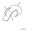
- the clip portion 4 includes a cylindrical clip base 4a with an opening along its longitudinal direction, and a plate 4b, which extends from one end of the clip base 4a and bends toward the central axis of the cylinder of the cylindrical clip base 4a.
- the clip base 4a is covered by the band 5, while the plate 4b is exposed without any cover.
- the portion of the plate 4b next to the clip base 4a is a simple extension of the surface of the cylinder of the clip base 4a, but the top portion of the plate 4b is bent toward the central axis of the cylinder of the clip base 4a.
- Surface fasteners 6, 7 are mounted on both ends of the band 5 so that the band 5 is fastened when the device is worn on a wrist.
- This pulse wave detection device has a main body 1a, which includes the pressure sensing unit 2, air bag 3, clip base 4a and the portion of the band 5 which carries or contains the aforementioned components of the device.
- the plate 4b extends from the clip base 4a toward the distal end of the hand of the subject wearing the pulse wave detection device 1.
- This configuration makes it easier to mount the device on a wrist because of the unitary combination of the main body 1a and the device for restricting the movement of a hand (plate 4b), and yet ensures an accurate and stable detection of pulse wave.
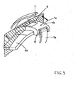
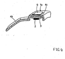
- FIG. 3 is a perspective view of a pulse wave detection device and FIG. 4 is a cross-sectional view of the device shown in FIG. 3 through the plane indicated by the arrow in FIG. 3 .
- the portion denoted by reference numeral 4c corresponds to the clip base 4a of the first embodiment shown in FIG. 1 and forms a casing for the main body 1a of the pulse wave detection device.
- a plate 4b extends from the casing 4c toward the distal end of a hand wearing the pulse wave detection device and bends toward back side of the hand.
- the size and the shape of the plate 4b are essentially the same as the plate shown in FIGS. 1 and 2 .
- One end of a band 5a is fixed to the casing 4c of the main body 1a through an axis 8 of the casing 4c, and the other end of the band 5a has a surface fastener 7, which engages with a surface fastener 9 mounted on the casing 4c.
- the pulse wave detection device of the second configuration is mounted on a wrist of a subject so that the plate 4b is, as shown in FIG. 5 , in direct contact with the palm (A) side of the hand through a proper adjustment of the band 5a and the fasteners 7, 9.
- the rotation of the wrist joint is restricted during detection, since the main body 1a and the plate 4b hinder the movement of the hand relative to the wrist portion.
- the pulse wave detection device of the first configuration shown in FIG. 1 should be mounted on the wrist of a subject so that the plate 4b is in direct contact with the palm side of the subject's hand.
- FIG. 6 is a schematic view of a pulse wave detection device of a third configuration.
- a plate 4b extends from the main body 1a toward the distal end of the hand, and bends toward the back (B) side of the hand. Although it is not shown in FIG. 6 , plate 4b is connected to and supported by the main body 1a.
- the pulse wave detection device of the third configuration is mounted on the wrist so that the plate 4b is in direct contact with the back side of the hand.
- FIG. 7 is a schematic view of a pulse wave detection device of a fourth configuration.
- This device has two p lates 4b1, 4b2, extending toward the distal end of the hand.
- Plate 4b1 on the back (B) side of the hand extends from the band 5a, and 4b2 on the palm (A) side extends from the main body 1a.
- the device is mounted on the wrist so that plate 4b1 is in direct contact with the back side of the hand and plate 4b2 is in direct contact with the palm of the hand.
- This configuration ensures more stable detection of the pulse wave because the movement of the hand is restricted by the two plates 4b1, 4b2 on both sides of the hand.
- FIG. 8 is a schematic view of a pulse wave detection device of a fifth configuration.
- This device includes a band 10, which is connected to the plate 4b at its distal end and is used for tying the palm or fingers to the plate 4b, in addition to the band 5a used for mounting the device on the wrist.
- the subject or another person first temporarily mounts the main body 1a of the pulse wave detection device on the wrist so that the plate 4b is in direct contact with the palm (A) of the hand on which the band 5a is mounted, then adjusts the position of the plate 4b relative to the hand, ties the palm or fingers to the plate 4b using the band 10, and finally tightly mounts the device on the wrist.
- the movement of the hand and the rotation of the wrist joint are further restricted because the hand is tied to the plate 4b using the belt 10.
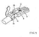
- FIG. 9 is a schematic view of a pulse wave detection device of a sixth configuration.
- This device includes a marking 11 for positioning the fingers, which is formed on the upper surface of the plate 4b at its distal end.
- the plate 4b extends from the main body 1a and has the marking along the center line of the plate 4b.
- the pressure sensing unit 2 is placed at or near the artery of the wrist for pulse wave detection.
- This configuration ensures pulse wave detection of high accuracy by adjusting the mounting of the main body 1a with the band 5a so that the marking 11 lies on the line running through the center of the middle finger.
- FIG. 10 is a schematic view of a pulse wave detection device of a seventh configuration.
- this device includes a band 10 which is connected to the plate 4b at its distal end and is used for tying the palm or fingers to the plate 4b, in addition to the band 5a used for mounting the device on the wrist. Similarly, the movement of the hand and thus the rotation of the wrist joint are further restricted with the hand being fixed to the plate 4b.
- one end of the band 10 is fixed on the upper surface of the plate 4b at its distal end.
- a marking 11 is formed for the alignment of the middle finger, and serves the same purpose as the marking 11 of the sixth configuration shown in FIG. 9 .
- the band 10 of the seventh configuration has a hole 12 for receiving the thumb when the band 10 is wrapped around the hand for tying it to the plate 4b.
- a subject of detection wears this device, he or she first puts the main body 1a on the wrist so that the plate 4b is in direct contact with the palm (A) of the hand, puts the thumb through the hole 12, grabs the plate 4b with the thumb through the hole 12, and adjusts the alignment between the marking 11 and the middle finger so that a proper positioning of the device relative to the hand is secured by fastening the two bands 5a, 10.
- This configuration ensures a reliable mounting of the pulse wave detection device even when the subject of detection wears the device by itself.
- the plate 4b and clip base 4a may be formed as two separate parts and integrally combined through a slide mechanism and fixation by a screw or other fastening structure.
- this configuration which falls within the scope of the invention according to claim 5, it is possible to adjust the length of the plate 4b in accordance with the size of the hand of a subject of detection.
- FIG. 11 is a perspective view of a pulse wave detection device of a eighth configuration
- the FIG. 12 is a perspective view of the device shown in FIG. 11 cut along a direction parallel to the longitudinal direction of the device.
- FIG. 13 shows a pulse wave detection device in which batteries 21, a display unit 22, an operation unit 23, a circuit board 24 and a compressed air manipulation system 25 including a pump and a pressure control valve are consolidated within the main body 1a.
- the size and weight of the main body 1a inevitably increase and thus result in a difficulty of mounting the device on the wrist because of an improper weight balance of the device and a high center of gravity position of the device.
- the portion indicated by the thick line in FIG. 13 is the core of the device housing only the pressure sensing unit 2 and a pressurizing unit such as an air bag 3.
- This configuration reduces the size and weight of the main body 1a by disposing in the plate 4b all or a part of the components of the device described above, including the butteries 21, the display unit 22, the operation unit 23, the circuit board 24 and the compressed air manipulation system 25. As a result, the ease of mounting the device on a wrist improves because of the improved weight balance of the device.
- FIG. 14 shows common components of blood pressure monitors described below as embodiments of this invention.
- a wrist blood pressure monitor 100E includes a main body 101 containing a control device for controlling the blood pressure detection, and a cuff 102 for mounting the main body 101 on a wrist.
- the main body 101 has a display unit 103 and a start switch 104 on its top surface, and, as shown in FIG. 15 , contains a pressure sensing unit 220, a pump 222 for compressing the air, a deflation valve 224 and a CPU for controlling these components of the blood pressure monitor.
- the cuff 102 is a band 110 which has an air bag 109 therein for receiving compressed air sent form the pump 222 contained in the main body 101 and for pressurizing the artery of wrist during blood pressure detection.
- the band also has a surface fastener 111 for fastening the band 110 around the wrist.
- the pressure sensing unit 220 does not directly touch the wrist for detecting the pulse wave of the artery as is the case with the pulse wave detection device described above. Rather, the pressure sensing unit 220 of the blood pressure monitor is placed between the air bag 109 and the deflation valve 224.
- the air bag 109 is first filled with compressed air from the pump 222 for pressurizing the wrist portion until the artery is closed, the pumping is then stopped, and the deflation valve 224 is controlled by the CPU for slowly deflating the air bag 109.
- the pressure sensing unit 220 detects the pressure of the air bag 109, which is a combination of the air pressure and pressure due to the pulse wave.
- the CPU derives the pulse wave component from the total pressure measured, and finds a maximum blood pressure when the pulse wave appears and a minimum blood pressure when the pulse wave disappears. As a modification, it is also possible to find the maximum and minimum blood pressure during the pressurization of the air bag 109 in a converse fashion.
- FIG. 15 shows a cross-sectional view of the blood pressure monitor 100E of FIG. 14 , which is mounted on a wrist and has the air bag 109 filled with the compressed air for the detection.
- the main body 101 of the blood pressure monitor 100E contains a pump 222 for generating the compressed air, a deflation valve 224, and a pressure sensing unit 220.
- the band 110 is fastened so that the air bag 109 is placed over the radialis 205 of the wrist portion for properly pressurizing the radialis 205 during detection.
- the radius 202 on the thumb side of the cross section is also shown in the figure. Also shown in the figure are the radius 202 on the thumb side of the cross section, the ulna 203 on the little finger side, flexor digitorum profundus 204a, palmaris longus 204b, flexor digitorum superficialis 206a, flexor carpi ulnaris 206b, and the ulnaris 207.
- FIG. 18 is a schematic side view of a blood pressure monitor 100A mounted on a wrist as an embodiment of this invention
- FIG. 19 is a schematic side view of the blood pressure monitor 100A in which the main body of the device is moved toward the distal end of the hand.
- the wrist blood pressure monitor 100A of thise embodiment has a main body 101 which is slidably mounted on a cuff 102.
- the mechanism for moving the main body 101 toward the distal end of the hand is a slide rail 101a provided between the main body 101 and the cuff 102. It is also possible to use other slide mechanism known in the art including linear bearings to replace the slide rail 101a as a means for moving the main body 101 in this embodiment.
- the main body 101 when moved toward the distal end of the hand as shown in FIG. 19 , serves as a regulating portion for restricting the movement of the hand.
- the range of motion of the hand is smaller when the main body 101 is moved (A2 in FIG. 19 ) than it is when the main body 101 is positioned on the cuff (A1 in FIG. 18 ).
- FIG. 20 is a schematic side view of a blood pressure monitor 100B mounted on a wrist as an embodiment of the invention
- FIG. 21 is a schematic plan view of the blood pressure monitor 100B of FIG. 20 mounted on the wrist of a subject.
- the wrist blood pressure monitor 100B of this embo diment has a guide portion 120 extending toward the distal end of the hand.
- This guide portion 120 may be made of a plastic material such as ABS or polypropylene, and may be connected to either the main body 101 or the cuff 102.
- the guide portion 120 serves as a regulating portion for restricting the movement of the hand. As a result, more accurate application of the air bag pressure to the artery is achieved because the guide portion 120 prevents the hand from bending toward its palm side enough to allow the tendons to hinder detection.
- the guide portion 120 may be detachably mounted on the blood pressure monitor 100B, or it may be retractable into the blood pressure monitor 100B itself. Either configuration improves the handling of the blood pressure monitor 100B during its mounting on and detaching from the wrist.
- FIG. 22 is a schematic plan view of a blood pressure monitor 100C mounted on a wrist as another embodiment of the invention
- FIG. 23 is a schematic plan view of the device of FIG. 22 in which a guide portion 120 is extended toward the distal end of the hand.
- the wrist blood pressure monitor 100C of the embodiment of figure 22 has a guide portion 120 which is the same as the guide portion 120 of the embodiment of figure 20 .
- the guide portion 120 of the embodiment of figure 22 is extended toward the distal end of the hand based on a slide mechanism in synchronization with the slide movement of the main body 101 toward the distal end.
- the slide mechanism of the embodiment of figure 18 may be used in the embodiment of figure 22 .
- the blood pressure monitor 100C also has a switching mechanism which activates the blood pressure monitor 100C when the main body 101 is moved toward the distal end of the hand.
- the switching mechanism may be based on a pair of a detent and a projection formed between main body 101 and slide mechanism 101a.
- the engagement of the detent and the projection for example, switches on the blood pressure monitor 100C, and disengagement of the detent and projection switches off the device.
- the engagement may switch off the device and the disengagement switch on the device.
- Other switching mechanisms known in the art may be applied to this embodiment.
- the guide portion 120 which extends toward the distal end of the hand in synchronization with the slide movement of the main body 101, serves as a regulating portion for restricting the movement of the hand. As a result, more accurate application of the air bag pressure to the artery is achieved because the guide portion 120 prevents the hand from bending toward its palm side enough to allow the tendons to hinder the detection.
- the blood pressure monitor 100C of the eleventh embodiment which is switched on for the detection only when the main body 101 is moved toward the distal end of the hand, ensures that the regulating portion for restricting the movement of the hand (the main body 101 or the guide portion 120) is always in place during the detection of blood pressure.
- this configuration elimina tes the need for a start switch mounted on the top surface of the main body 101, and thus makes it possible to have a larger display unit on the top surface of the main body 101 for better display of the information on the display unit, including measured blood pressure values.
- the wrist blood pressure monitor of the embodiment of figure 22 has both the slide mechanism for the guide portion 120 in synchronization with the slide movement of the main body 101 and the switching mechanism in synchronizatio n with the same movement, each of the two mechanisms may be provided separately for a blood pressure monitor.
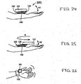
- FIG. 24 is a schematic side view of a blood pressure monitor 100D mounted on a wrist as a further embodiment of the invention
- FIG. 25 is a schematic side view of the blood pressure monitor 100D of FIG. 24 in which a guide portion is rotated out toward the distal end of the hand
- FIG. 26 is a schematic plan view of the blood pressure monitor 100D of FIG. 25 .
- the main body 101 of the wrist blood pressure monitor 100D of this embodiment can be rotated out toward the distal end of the hand from the cuff 102.
- the rotating mechanism of this embodiment is a rotation axis 130 provided between the main body 101 and the cuff 102. As shown in FIG. 25 , the main body 101 is swung around the rotation axis 130 in the direction of R shown in the figure.
- the main body 101 when rotated out toward the distal end of the hand as shown in FIG. 25 , serves as a regulating portion for restricting the movement of the hand.
- the range of motion of the hand is smaller when the main body 101 is rotated out (A2 in FIG. 25 ) than it is when the main body 101 is positioned on the cuff (A1 in FIG. 24 ).
- the features described for the pulse wave detection device may be applicable to the blood pressure meter, and those for the blood pressure meter may be applicable to the pulse wave detection device, as long as the features meet the requirements of restricting the movement of hand of a particular device.
- the plate for restricting the movement of hand of the first described configuration as a pulse wave detection device may be detachably mounted on the main body for the ease of mounting the device on the wrist, or may be extended toward the distal end of the hand for a better restriction of the movement of hand.
- a wrist blood pressure meter may have a plate extending from the main body for properly restricting the movement of hand for an accurate detection.
Landscapes
- Health & Medical Sciences (AREA)
- Life Sciences & Earth Sciences (AREA)
- Surgery (AREA)
- Animal Behavior & Ethology (AREA)
- Pathology (AREA)
- Engineering & Computer Science (AREA)
- Biomedical Technology (AREA)
- Heart & Thoracic Surgery (AREA)
- Medical Informatics (AREA)
- Molecular Biology (AREA)
- Physics & Mathematics (AREA)
- Biophysics (AREA)
- General Health & Medical Sciences (AREA)
- Public Health (AREA)
- Veterinary Medicine (AREA)
- Cardiology (AREA)
- Vascular Medicine (AREA)
- Ophthalmology & Optometry (AREA)
- Dentistry (AREA)
- Physiology (AREA)
- Measuring Pulse, Heart Rate, Blood Pressure Or Blood Flow (AREA)
Claims (9)
- Biosignal-Nachweisvorrichtung, welche für eine Anbringung an einem Handgelenk eines Subjekts eingerichtet ist, aufweisend:einen zur Anbringung auf einer Handflächenseite des Handgelenks eingerichteten Grundkörper (101);eine Druckabfühleinheit (220) zum Abfühlen einer Pulswelle;eine Unterdrucksetzungseinheit zum Aufbringen von Druck auf einen Nachweisabschnitt des Handgelenks;eine zur Anbringung des Grundkörpers an der Handflächenseite des Handgelenks eingerichtete Manschette (102); undeinen Regulierungsabschnitt zur Beschränkung der Bewegung der Hand, wobei der Regulierungsabschnitt so eingerichtet ist, dass er sich entlang der Richtung der Hand erstreckt, und so eingerichtet, dass er auf einer Handflächenseite der Hand angeordnet werden kann; gekennzeichnet durcheinen Bewegungsmechanismus (101a) zum Bewegen des Grundkörpers (101) oder eines Abschnitts des Grundkörpers zum distalen Ende der Hand hin, so dass der Grundkörper oder der Abschnitt des Grundkörpers als der Regulierungsabschnitt dient.
- Biosignal-Nachweisvorrichtung nach Anspruch 1, welche ferner einen Schaltmechanismus aufweist, welcher die Vorrichtung aktiviert, wenn der Grundkörper (101) oder der Abschnitt des Grundkörpers zum distalen Ende der Hand hin bewegt wird.
- Biosignal-Nachweisvorrichtung nach Anspruch 1, wobei der zum distalen Ende bewegte Abschnitt des Grundkörpers (101) ein zum distalen Ende hin erstreckbarer Führungsabschnitt (120) ist.
- Biosignal-Nachweisvorrichtung nach Anspruch 3, wobei der Führungsabschnitt (120) lösbar am Grundkörper (101) angebracht ist.
- Biosignal-Nachweisvorrichtung, welche für eine Anbringung an einem Handgelenk eines Subjekts eingerichtet ist, aufweisend:einen zur Anbringung auf der Handflächenseite des Handgelenks aufgebauten Grundkörper (1a);eine Druckabfühleinheit (2) zum Abfühlen einer Pulswelle;eine Unterdrucksetzungseinheit zum Aufbringen von Druck auf die Druckabfühleinheit an einem Nachweisabschnitt des Handgelenks;eine zur Anbringung des Grundkörpers (1a) an der Handflächenseite des Handgelenks eingerichtete Manschette (5); undeinen Regulierungsabschnitt (4) zur Beschränkung der Bewegung der Hand, wobei der Regulierungsabschnitt so eingerichtet ist, dass er sich entlang der Richtung der Hand erstreckt, und so eingerichtet, dass er auf einer Handflächenseite der Hand angeordnet werden kann, dadurch gekennzeichnet, dass der Regulierungsabschnitt zwei getrennte Teile (4a, 4b) aufweist, die über einen Gleitmechanismus zusammengefügt sind, so dass die Länge des Regulierungsabschnitts einstellbar ist.
- Biosignal-Nachweisvorrichtung nach Anspruch 5, wobei der Regulierungsabschnitt (4) auch für ein Vorsehen auf der Rückseite der Hand eingerichtet ist.
- Biosignal-Nachweisvorrichtung nach Anspruch 5, welche ferner einen zweiten Regulierungsabschnitt (4b1) aufweist, der für ein Vorsehen auf der Rückseite der Hand eingerichtet ist.
- Biosignal-Nachweisvorrichtung nach Anspruch 7, welche ferner ein Band (5) zum Binden der Hand an den Regulierungsabschnitt (4) aufweist.
- Biosignal-Nachweisvorrichtung nach Anspruch 7, welche ferner ein Band (5) zum Binden der Hand an die Regulierungsabschnitte (4b1, 4b2) aufweist.
Applications Claiming Priority (4)
| Application Number | Priority Date | Filing Date | Title |
|---|---|---|---|
| JP2000378437 | 2000-12-13 | ||
| JP2000378437A JP2002177227A (ja) | 2000-12-13 | 2000-12-13 | 脈波検出装置 |
| JP2001188252A JP3721410B2 (ja) | 2001-06-21 | 2001-06-21 | 手首式血圧計 |
| JP2001188252 | 2001-06-21 |
Publications (3)
| Publication Number | Publication Date |
|---|---|
| EP1214904A2 EP1214904A2 (de) | 2002-06-19 |
| EP1214904A3 EP1214904A3 (de) | 2002-08-21 |
| EP1214904B1 true EP1214904B1 (de) | 2008-02-20 |
Family
ID=26605723
Family Applications (1)
| Application Number | Title | Priority Date | Filing Date |
|---|---|---|---|
| EP01129635A Expired - Lifetime EP1214904B1 (de) | 2000-12-13 | 2001-12-12 | Am Handgelenk getragene Biosignaldetektionsvorrichtung |
Country Status (3)
| Country | Link |
|---|---|
| US (2) | US20020077558A1 (de) |
| EP (1) | EP1214904B1 (de) |
| DE (1) | DE60132875T2 (de) |
Families Citing this family (31)
| Publication number | Priority date | Publication date | Assignee | Title |
|---|---|---|---|---|
| JP2004215915A (ja) * | 2003-01-15 | 2004-08-05 | Omron Healthcare Co Ltd | 血圧計用カフ |
| JP3821099B2 (ja) * | 2003-01-24 | 2006-09-13 | オムロンヘルスケア株式会社 | 脈波測定装置 |
| US7341561B2 (en) * | 2003-05-30 | 2008-03-11 | Casio Computer Co., Ltd. | Wrist-worn high-accuracy pulsation measuring apparatus |
| JP2006000337A (ja) * | 2004-06-17 | 2006-01-05 | Omron Healthcare Co Ltd | 電子血圧計 |
| JP4590998B2 (ja) * | 2004-09-15 | 2010-12-01 | オムロンヘルスケア株式会社 | 血圧計 |
| US20060111637A1 (en) * | 2004-11-23 | 2006-05-25 | Jacober Jeffrey M | Wrist-mount blood pressure monitor with auditory feature |
| US20060111636A1 (en) * | 2004-11-23 | 2006-05-25 | Jacober Jeffrey M | Wrist-mount blood pressure monitor |
| US7585280B2 (en) | 2004-12-29 | 2009-09-08 | Codman & Shurtleff, Inc. | System and method for measuring the pressure of a fluid system within a patient |
| US7060034B1 (en) * | 2005-03-15 | 2006-06-13 | Health & Life Co., Ltd. | Tunnel type electronic sphygmomanometer measuring unit assembly |
| KR20080068471A (ko) * | 2007-01-19 | 2008-07-23 | 삼성전자주식회사 | 휴대형 생체 신호 측정 장치 |
| TWM328632U (en) * | 2007-06-08 | 2008-03-11 | Mesure Technology Co Ltd | Sensitive patch, mounting belt device and wireless monitoring device |
| WO2009017113A1 (ja) * | 2007-07-31 | 2009-02-05 | Sysmex Corporation | 非侵襲生体計測装置、および非侵襲生体計測方法 |
| JP2012200508A (ja) * | 2011-03-28 | 2012-10-22 | Omron Healthcare Co Ltd | 血圧情報測定装置用カフおよびこれを備えた血圧情報測定装置 |
| US9392970B2 (en) | 2011-08-10 | 2016-07-19 | Wristdocs Llc | Biotelemetry system |
| KR101455269B1 (ko) | 2013-04-18 | 2014-10-31 | 주식회사 비젼스케이프 | 박막형 압력 센서를 이용한 손목형 혈압측정장치 |
| CN103677131B (zh) * | 2013-12-11 | 2017-12-29 | 华为技术有限公司 | 一种穿戴式电子设备及其显示方法 |
| RS20140247A1 (en) | 2014-05-14 | 2015-12-31 | Novelic D.O.O. | RADAR SENSOR FOR DETECTION OF SIGNS OF LIFE OPERATING IN THE MILLIMETER FREQUENCY RANGE AND METHOD OF OPERATION |
| CN104434053A (zh) * | 2014-07-02 | 2015-03-25 | 许建平 | 一种电子检测装置 |
| CN105125195A (zh) * | 2015-06-24 | 2015-12-09 | 惠州Tcl移动通信有限公司 | 一种使血压传感器贴紧手腕的方法及智能穿戴设备 |
| JP6597083B2 (ja) * | 2015-09-07 | 2019-10-30 | オムロンヘルスケア株式会社 | 脈波検出装置 |
| CN105125196B (zh) * | 2015-09-18 | 2018-09-14 | 深圳邦普医疗设备系统有限公司 | 一种电子血压计 |
| CN105105760B (zh) * | 2015-09-28 | 2019-04-26 | 联想(北京)有限公司 | 一种电子设备和检测方法 |
| CN105769155A (zh) * | 2016-02-19 | 2016-07-20 | 康泰医学系统(秦皇岛)股份有限公司 | 一种无需测试时充放气的腕表血压计及其施压方法 |
| TWI670046B (zh) * | 2016-03-29 | 2019-09-01 | 豪展醫療科技股份有限公司 | 兼具情緒壓力指數檢測與血壓檢測之量測裝置與方法 |
| FR3051343B1 (fr) * | 2016-05-19 | 2018-09-28 | Spengler Sas | Brassard gonflable pour sphygmomanometre |
| JP6610433B2 (ja) | 2016-05-27 | 2019-11-27 | オムロンヘルスケア株式会社 | センサアセンブリ |
| JP6693274B2 (ja) * | 2016-05-27 | 2020-05-13 | オムロンヘルスケア株式会社 | 血圧測定用カフおよび血圧計 |
| KR101945960B1 (ko) * | 2016-11-23 | 2019-02-08 | (주)참케어 | 손목 혈압계 |
| TWI655929B (zh) * | 2016-12-01 | 2019-04-11 | 深禾醫學科技股份有限公司 | 具血壓量測功能的穿戴式裝置 |
| CN108451519A (zh) * | 2018-02-23 | 2018-08-28 | 均威科技(深圳)有限公司 | 腕式电子血压计手带 |
| CN109770869A (zh) * | 2019-03-19 | 2019-05-21 | 中北大学 | 可施压脉搏波采集装置 |
Family Cites Families (15)
| Publication number | Priority date | Publication date | Assignee | Title |
|---|---|---|---|---|
| US4993422A (en) * | 1986-05-02 | 1991-02-19 | The Hon Group | Apparatus for measuring blood pressure |
| US5240007A (en) * | 1991-05-14 | 1993-08-31 | Ivac Corporation | Apparatus and method for moving a tissue stress sensor for applanating an artery |
| US5494043A (en) * | 1993-05-04 | 1996-02-27 | Vital Insite, Inc. | Arterial sensor |
| US5558095A (en) * | 1994-08-29 | 1996-09-24 | Hynson; James M. | Method and device for increasing hand vascular resistance during blood pressure measurement |
| CN1128648A (zh) * | 1994-10-07 | 1996-08-14 | 欧姆龙株式会社 | 血压计 |
| US5766131A (en) * | 1995-08-04 | 1998-06-16 | Seiko Epson Corporation | Pulse-wave measuring apparatus |
| AU7383896A (en) * | 1995-10-02 | 1997-04-28 | Edward H. Hon | Improved blood pressure monitoring cuff |
| US5652955A (en) * | 1996-03-22 | 1997-08-05 | Skewis; Kathleen A. | Wrist protector |
| JPH1133007A (ja) * | 1997-07-14 | 1999-02-09 | Nippon Colin Co Ltd | 圧脈波検出用手首固定装置 |
| JP3164114B2 (ja) * | 1998-01-13 | 2001-05-08 | オムロン株式会社 | 手首用血圧計 |
| US6132383A (en) * | 1998-03-20 | 2000-10-17 | Hypertension Diagnostics, Inc. | Apparatus for holding and positioning an arterial pulse pressure sensor |
| AU3955500A (en) * | 1999-04-21 | 2000-11-02 | Jie Kan | A noninvasive blood pressure measuring method and apparatus |
| US6471655B1 (en) * | 1999-06-29 | 2002-10-29 | Vitalwave Corporation | Method and apparatus for the noninvasive determination of arterial blood pressure |
| US6142966A (en) * | 1999-08-05 | 2000-11-07 | Weber Orthopedic, Inc. | Wrist orthosis |
| US6839584B2 (en) * | 2000-05-02 | 2005-01-04 | Instrumentation Metrics, Inc. | Method and apparatus for minimizing spectral interference due to within and between sample variations during in-situ spectral sampling of tissue |
-
2001
- 2001-12-07 US US10/005,892 patent/US20020077558A1/en not_active Abandoned
- 2001-12-12 DE DE60132875T patent/DE60132875T2/de not_active Expired - Lifetime
- 2001-12-12 EP EP01129635A patent/EP1214904B1/de not_active Expired - Lifetime
-
2004
- 2004-09-13 US US10/938,958 patent/US20050033187A1/en not_active Abandoned
Non-Patent Citations (1)
| Title |
|---|
| None * |
Also Published As
| Publication number | Publication date |
|---|---|
| DE60132875T2 (de) | 2009-03-05 |
| EP1214904A3 (de) | 2002-08-21 |
| US20050033187A1 (en) | 2005-02-10 |
| US20020077558A1 (en) | 2002-06-20 |
| EP1214904A2 (de) | 2002-06-19 |
| DE60132875D1 (de) | 2008-04-03 |
Similar Documents
| Publication | Publication Date | Title |
|---|---|---|
| EP1214904A2 (de) | Am Handgelenk getragene Biosignaldetektionsvorrichtung | |
| JP4306381B2 (ja) | 脈波測定装置用手首固定具および脈波測定装置 | |
| US6379310B1 (en) | Wrist sphygmomanometer | |
| US20100234182A1 (en) | Neurological device | |
| US4433486A (en) | Measuring instrument for compressible objects | |
| US6651352B2 (en) | Wrist motion measurement device | |
| US5072927A (en) | Hand exercise device | |
| JP5919706B2 (ja) | バンド及び電子機器 | |
| CA1091124A (en) | Eyebrow contour guide | |
| US5904280A (en) | Wrist--mountable device | |
| CA2635383A1 (en) | Cervical dilation measurement apparatus | |
| JP2009240511A (ja) | 生体測定装置 | |
| US7033330B2 (en) | Wrist brace | |
| KR101485481B1 (ko) | 손가락 재활치료 장치 | |
| CN101204324B (zh) | 血压计 | |
| TW200816958A (en) | Pulsometer | |
| EP1440654B1 (de) | Vorrichtung zur Messung der Pulswelle | |
| JP3041401B2 (ja) | 脈波測定機器 | |
| CN212037845U (zh) | 偏瘫上肢良姿位摆放与训练装置 | |
| EP3243431B1 (de) | Gurt für eine tragbare pulsmessungsvorrichtung und tragbare pulsmessungsvorrichtung | |
| JP3721410B2 (ja) | 手首式血圧計 | |
| CN109069015A (zh) | 脉搏波检测装置和生物信息测量装置 | |
| CN113180625A (zh) | 一种血压测量手带 | |
| JPH025370Y2 (de) | ||
| CN222870504U (zh) | 一种防脱落的生命体征监护设备 |
Legal Events
| Date | Code | Title | Description |
|---|---|---|---|
| PUAI | Public reference made under article 153(3) epc to a published international application that has entered the european phase |
Free format text: ORIGINAL CODE: 0009012 |
|
| AK | Designated contracting states |
Kind code of ref document: A2 Designated state(s): AT BE CH CY DE DK ES FI FR GB GR IE IT LI LU MC NL PT SE TR |
|
| AX | Request for extension of the european patent |
Free format text: AL;LT;LV;MK;RO;SI |
|
| PUAL | Search report despatched |
Free format text: ORIGINAL CODE: 0009013 |
|
| AK | Designated contracting states |
Kind code of ref document: A3 Designated state(s): AT BE CH CY DE DK ES FI FR GB GR IE IT LI LU MC NL PT SE TR |
|
| AX | Request for extension of the european patent |
Free format text: AL;LT;LV;MK;RO;SI |
|
| 17P | Request for examination filed |
Effective date: 20030124 |
|
| AKX | Designation fees paid |
Designated state(s): DE FR GB IT |
|
| RAP1 | Party data changed (applicant data changed or rights of an application transferred) |
Owner name: OMRON HEALTHCARE CO., LTD. |
|
| RAP1 | Party data changed (applicant data changed or rights of an application transferred) |
Owner name: OMRON HEALTHCARE CO., LTD. |
|
| 17Q | First examination report despatched |
Effective date: 20051020 |
|
| GRAP | Despatch of communication of intention to grant a patent |
Free format text: ORIGINAL CODE: EPIDOSNIGR1 |
|
| GRAS | Grant fee paid |
Free format text: ORIGINAL CODE: EPIDOSNIGR3 |
|
| GRAA | (expected) grant |
Free format text: ORIGINAL CODE: 0009210 |
|
| AK | Designated contracting states |
Kind code of ref document: B1 Designated state(s): DE FR GB IT |
|
| REG | Reference to a national code |
Ref country code: GB Ref legal event code: FG4D |
|
| RIN1 | Information on inventor provided before grant (corrected) |
Inventor name: TANABE, KAZUHISA,C/O OMRON CORPORATION Inventor name: ITONAGA, KAZUNOBU,C/O OMRON CORPORATION Inventor name: KATO, HIROYUKI,C/O OMRON CORPORATION Inventor name: SANO, YOSHIHIKO,C/O OMRON CORPORATION Inventor name: TANAKA, TAKAHIDE,C/O OMRON CORPORATION Inventor name: OHTANI, TOSHIO,C/O OMRON CORPORATION Inventor name: OKU, SHOJIRO,C/O OMRON CORPORATION |
|
| REF | Corresponds to: |
Ref document number: 60132875 Country of ref document: DE Date of ref document: 20080403 Kind code of ref document: P |
|
| ET | Fr: translation filed | ||
| PLBE | No opposition filed within time limit |
Free format text: ORIGINAL CODE: 0009261 |
|
| STAA | Information on the status of an ep patent application or granted ep patent |
Free format text: STATUS: NO OPPOSITION FILED WITHIN TIME LIMIT |
|
| 26N | No opposition filed |
Effective date: 20081121 |
|
| GBPC | Gb: european patent ceased through non-payment of renewal fee |
Effective date: 20081212 |
|
| REG | Reference to a national code |
Ref country code: FR Ref legal event code: ST Effective date: 20090831 |
|
| PG25 | Lapsed in a contracting state [announced via postgrant information from national office to epo] |
Ref country code: GB Free format text: LAPSE BECAUSE OF NON-PAYMENT OF DUE FEES Effective date: 20081212 |
|
| PG25 | Lapsed in a contracting state [announced via postgrant information from national office to epo] |
Ref country code: FR Free format text: LAPSE BECAUSE OF NON-PAYMENT OF DUE FEES Effective date: 20081231 |
|
| REG | Reference to a national code |
Ref country code: DE Ref legal event code: R082 Ref document number: 60132875 Country of ref document: DE Representative=s name: KILIAN KILIAN & PARTNER, DE |
|
| PGFP | Annual fee paid to national office [announced via postgrant information from national office to epo] |
Ref country code: DE Payment date: 20121227 Year of fee payment: 12 |
|
| REG | Reference to a national code |
Ref country code: DE Ref legal event code: R119 Ref document number: 60132875 Country of ref document: DE |
|
| PG25 | Lapsed in a contracting state [announced via postgrant information from national office to epo] |
Ref country code: IT Free format text: LAPSE BECAUSE OF NON-PAYMENT OF DUE FEES Effective date: 20081212 |
|
| REG | Reference to a national code |
Ref country code: DE Ref legal event code: R119 Ref document number: 60132875 Country of ref document: DE Effective date: 20140701 |
|
| PG25 | Lapsed in a contracting state [announced via postgrant information from national office to epo] |
Ref country code: DE Free format text: LAPSE BECAUSE OF NON-PAYMENT OF DUE FEES Effective date: 20140701 |