EP1214986A1 - Atomiseur à ultrasons - Google Patents
Atomiseur à ultrasons Download PDFInfo
- Publication number
- EP1214986A1 EP1214986A1 EP00127359A EP00127359A EP1214986A1 EP 1214986 A1 EP1214986 A1 EP 1214986A1 EP 00127359 A EP00127359 A EP 00127359A EP 00127359 A EP00127359 A EP 00127359A EP 1214986 A1 EP1214986 A1 EP 1214986A1
- Authority
- EP
- European Patent Office
- Prior art keywords
- ultrasonic atomizer
- substrate board
- substrate
- piezoelectric vibrator
- liquid
- Prior art date
- Legal status (The legal status is an assumption and is not a legal conclusion. Google has not performed a legal analysis and makes no representation as to the accuracy of the status listed.)
- Withdrawn
Links
- 239000000758 substrate Substances 0.000 claims abstract description 59
- XEEYBQQBJWHFJM-UHFFFAOYSA-N Iron Chemical compound [Fe] XEEYBQQBJWHFJM-UHFFFAOYSA-N 0.000 claims description 18
- 238000004519 manufacturing process Methods 0.000 claims description 10
- 229910052742 iron Inorganic materials 0.000 claims description 8
- 239000007921 spray Substances 0.000 claims description 5
- 229910000831 Steel Inorganic materials 0.000 claims description 4
- 239000010959 steel Substances 0.000 claims description 4
- 239000002184 metal Substances 0.000 claims description 2
- 229910052751 metal Inorganic materials 0.000 claims description 2
- 239000002985 plastic film Substances 0.000 claims description 2
- 229920006255 plastic film Polymers 0.000 claims description 2
- 239000004922 lacquer Substances 0.000 claims 1
- 239000007788 liquid Substances 0.000 description 22
- 230000005284 excitation Effects 0.000 description 6
- 238000000889 atomisation Methods 0.000 description 4
- 238000009826 distribution Methods 0.000 description 4
- 239000003595 mist Substances 0.000 description 3
- XLYOFNOQVPJJNP-UHFFFAOYSA-N water Substances O XLYOFNOQVPJJNP-UHFFFAOYSA-N 0.000 description 3
- 230000005484 gravity Effects 0.000 description 2
- 238000010409 ironing Methods 0.000 description 2
- 238000000034 method Methods 0.000 description 2
- 239000000853 adhesive Substances 0.000 description 1
- 230000001070 adhesive effect Effects 0.000 description 1
- 239000012790 adhesive layer Substances 0.000 description 1
- 239000000443 aerosol Substances 0.000 description 1
- 230000000295 complement effect Effects 0.000 description 1
- 230000007797 corrosion Effects 0.000 description 1
- 238000005260 corrosion Methods 0.000 description 1
- 230000008878 coupling Effects 0.000 description 1
- 238000010168 coupling process Methods 0.000 description 1
- 238000005859 coupling reaction Methods 0.000 description 1
- 230000006735 deficit Effects 0.000 description 1
- 230000000694 effects Effects 0.000 description 1
- 230000002349 favourable effect Effects 0.000 description 1
- 239000011888 foil Substances 0.000 description 1
- 230000017525 heat dissipation Effects 0.000 description 1
- 239000000463 material Substances 0.000 description 1
- 239000003973 paint Substances 0.000 description 1
- 238000010422 painting Methods 0.000 description 1
- 238000005192 partition Methods 0.000 description 1
- 230000005855 radiation Effects 0.000 description 1
- 230000035945 sensitivity Effects 0.000 description 1
- 238000003860 storage Methods 0.000 description 1
- 238000002604 ultrasonography Methods 0.000 description 1
- 239000002966 varnish Substances 0.000 description 1
- 238000009736 wetting Methods 0.000 description 1
Images


Classifications
-
- B—PERFORMING OPERATIONS; TRANSPORTING
- B05—SPRAYING OR ATOMISING IN GENERAL; APPLYING FLUENT MATERIALS TO SURFACES, IN GENERAL
- B05B—SPRAYING APPARATUS; ATOMISING APPARATUS; NOZZLES
- B05B17/00—Apparatus for spraying or atomising liquids or other fluent materials, not covered by the preceding groups
- B05B17/04—Apparatus for spraying or atomising liquids or other fluent materials, not covered by the preceding groups operating with special methods
- B05B17/06—Apparatus for spraying or atomising liquids or other fluent materials, not covered by the preceding groups operating with special methods using ultrasonic or other kinds of vibrations
- B05B17/0607—Apparatus for spraying or atomising liquids or other fluent materials, not covered by the preceding groups operating with special methods using ultrasonic or other kinds of vibrations generated by electrical means, e.g. piezoelectric transducers
- B05B17/0638—Apparatus for spraying or atomising liquids or other fluent materials, not covered by the preceding groups operating with special methods using ultrasonic or other kinds of vibrations generated by electrical means, e.g. piezoelectric transducers spray being produced by discharging the liquid or other fluent material through a plate comprising a plurality of orifices
- B05B17/0646—Vibrating plates, i.e. plates being directly subjected to the vibrations, e.g. having a piezoelectric transducer attached thereto
-
- D—TEXTILES; PAPER
- D06—TREATMENT OF TEXTILES OR THE LIKE; LAUNDERING; FLEXIBLE MATERIALS NOT OTHERWISE PROVIDED FOR
- D06F—LAUNDERING, DRYING, IRONING, PRESSING OR FOLDING TEXTILE ARTICLES
- D06F75/00—Hand irons
- D06F75/08—Hand irons internally heated by electricity
- D06F75/22—Hand irons internally heated by electricity with means for supplying liquid to the article being ironed
Definitions
- the invention relates to an ultrasonic atomizer for production of a liquid spray.
- Ultrasonic atomizers are used when the to generating spray mist high demands especially in relation distribution as homogeneous as possible or as possible good meterability. Possible areas of application are e.g. use in painting equipment, air humidification systems, medical devices - where a medical effective aerosol generated in a certain dosage - but also household appliances, such as Iron, in those to generate particularly good work success Ultrasonic atomizers are used to make a to produce water mist that supports the ironing process.
- EP 1 005 917 A1 describes an inhaler with an ultrasonic atomizer described. This consists of a first and a second substrate, and a vibration generator.
- the two substrates and the vibrator are essentially three-dimensional, specially designed bodies.
- the first substrate which is the outlet device for the atomized liquid is very important elaborately designed to the excited main vibration mode optimal support.
- the invention is therefore based on the object of an ultrasonic atomizer indicate which one is easy to manufacture, a favorable radiation behavior with regard to the to be generated Has spray mist and covers a wide range of uses.
- the task is performed by an ultrasonic atomizer solved with a piezoelectric transducer, at which the piezoelectric transducer as a whole-surface table is formed and connected to a substrate board.
- the invention is Ultrasonic atomizer easy to manufacture because it is used to manufacture the essential components of which do not require any special manufacturing steps in which one or more components of the atomizer a complicated three-dimensional geometric shape is given.
- Ultrasonic atomizer not limited to applications, where a relatively small amount of liquid is atomized shall be.
- Ultrasound atomizer understood a plate-like structure which are two flat, parallel interfaces having. Furthermore, this plate-like structure is said to be one have a small thickness compared to its length.
- a board is called the whole area if on one of the Interfaces two with respect to the center of gravity of the panel the opposite edge points always by a straight line Route can be connected, the routes being completely in of the respective area. Minor irregularities on The edge of the respective interface should not be considered become.
- the substrate board advantageously has at least one recess on.
- the targeted geometric design of the recess in the substrate board allows to set the vibration modes of the Formed consisting of piezoelectric vibrator and thus connected substrate board.
- the working frequency of the ultrasonic atomizer targeted to a frequency range far from the hearing limit away to avoid acoustic impairments to avoid during operation.
- the variation in the size and geometric shape of the recess the substrate board also allows targeted influence to take on the size of the atomization process resulting liquid droplets.
- the geometry of the piezoelectric transducer represents the Variation of the geometry of the recess of the substrate plate one technically easy to accomplish task.
- the recess advantageously extends over the geometric one Center of gravity of the substrate board with elliptical, circular or regular polynomial cross section of the substrate plate so about the center. This will make the adjustment to the desired vibration mode particularly easily.
- the piezoelectric vibrator and / or the substrate plate formed as at least essentially round plates.
- the vibrations along the surface of the piezoelectric Schwingers particularly homogeneous.
- the substrate board's job is to set certain vibration modes to stimulate or suppress is one in many Advantageous in terms of symmetrical shape of the substrate board, to achieve this effect as homogeneously as possible.
- round boards are easy to manufacture.
- Both the piezoelectric vibrator is advantageous as well as the substrate board as a round board, the substrate panel having a central hole.
- the symmetry properties come of the components involved are particularly good and complementary to unfolding.
- there is a middle one Hole can be easily made as a recess in the substrate board.
- Steel is a material that can be easily procured or manufactured is. Furthermore, a large number of simple ones and easy processing options for steel.
- the piezoelectric vibrator on the substrate board is advantageous glued on, especially the transducer and substrate board largely glued together.
- An adhesive connection is easy to produce and offers at Ultrasonic atomizer according to the invention the advantage that the most homogeneous possible distribution of the adhesive layer in comparison the vibrations of the piezoelectric vibrator connected to the substrate panel be little affected.
- the substrate board has at least one hole and this is closed by at least one aid.
- the aid has a thickness which is clear is below the thickness of the substrate board.
- Closing the hole in the substrate board with a tool offers the advantage that the especially in operation without Liquid heat generated by the piezoelectric vibrator can be dissipated more easily because the heat on the with aids in contact with the piezoelectric vibrator passes over and is distributed over its surface. If the surface of the aid is at least somewhat larger than the cross section of the hole, the heat input is improved, because the surface of the aid is directly related to the environment communicates. In operation with liquid offers the aid also has the advantage of corrosion protection of the piezoelectric transducer when the feed the liquid to be atomized from that facing away from the transducer Side of the substrate board. Then she kicks no longer in direct contact with the surface of the piezoelectric Oscillator.
- the aid is advantageously a plastic film and / or a paint and / or a metal foil.
- the ultrasonic atomizer in an iron is advantageous used to generate a spray.
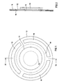
- the substrate board 12 has a recess 14 center hole. Both the piezoelectric vibrator 10 as well as the substrate board 12 are in this embodiment designed as round plates.
- the piezoelectric vibrator 10 and the substrate panel 12 form a sandwich arrangement and are preferably glued together flat.
- the one to be atomized This sandwich arrangement is on a liquid Not shown in FIG 1 way can be supplied.
- the substrate board 12 has through openings 16, through which, when operating the ultrasonic atomizer, the one to be atomized or pass through already atomized liquid can.
- the recess 14 of the substrate board 12 can be of geometrical sizes such as. Target length, width, area or diameter be designed so that the one is not closer shown excitation device consisting of excited unit with piezoelectric vibrator 10 and substrate board 12 with a desired working frequency swings.
- FIG. 2 shows a side view of FIG. 2 along the section II-II.
- the passage openings 16 are of a perforated film 18, which is perforated in the present exemplary embodiment Ring disc is covered.
- the not shown Holes in the perforated film 18 preferably have a diameter of approx. 50 ⁇ m. The purpose of these holes is that no liquid can pass through it if the ultrasonic atomizer is not actuated, i.e. the piezoelectric Vibrator is not excited.
- the perforated film 18 is preferably glued flat to the substrate board 12.
- FIG. 3 shows an ultrasonic atomizer 19. This is connected with a tank housing 29, which consists of two by one Partition 31 separate rooms (30, 32) there. In both There is clearing during the operation of the ultrasonic atomizer 16 liquid 34.
- the liquid in the working space 32 is the one which the next time you press a button, not shown Actuator of the ultrasonic atomizer 16 is used for atomization. A particularly good atomization result is obtained if one is possible in the work area 32 even distribution of pressure in the liquid prevails.
- liquid from the storage room 30 are specifically transported to the work area 32 in order to be there occurring during the operation of the ultrasonic atomizer 16 Compensate for pressure fluctuations in the liquid.
- the ultrasonic atomizer 19 further comprises an entire surface piezoelectric vibrator 20, which is on a substrate board 22, which in the present embodiment is designed as a disc, is glued on.
- the substrate board 22 has a central hole, which with a Aid 35, for example closed with a varnish is.
- the thickness of the aid 35 should be compared to the thickness the substrate board 22 may be small.
- the substrate panel 22 also has passage openings 26, which with a annular perforated film 28 or a porous washer are.
- the ultrasonic atomizer 19 is now operated by a Actuating device, not shown, is operated, so the piezoelectric vibrator 20 also experiences Excitation device, not shown, an electrical Excitation which is the unit which is made of piezoelectric Vibrator and substrate panel 22 is made to vibrate. With this excitation, the liquid is atomized into Liquid droplets that are small enough to pass through the Holes of the perforated film 28 to reach and through the passage openings 26 to be ejected in the R direction.
- the tool 35 with which the central hole of the substrate board is closed, then especially improves the Heat dissipation of the piezoelectric vibrator 20 when there is no liquid 34 in the tank housing 29 and the ultrasonic atomizer 19 is operated anyway. Furthermore offers closing the central hole of the substrate board by means of the aid 35 the advantage that the forces which is on the border between piezoelectric vibrator and Substrate board occur, are reduced and so the sensitivity to breakage is reduced.
- the iron 40 includes an ultrasonic atomizer, which is fed with liquid from a tank housing 46 and a perforated film 54, a substrate board 52 and a piezoelectric Contains transducer 48.
- the piezoelectric Vibrator 48 is connected via a connecting line 50 from one Excitation device, not shown, controlled and closed Vibrations stimulated.
- the ultrasonic atomizer or at least whose excitation device is also not one Actuator shown actuates what to swing of the piezoelectric vibrator 48 leads.
- Vibrations form in the tank housing 46 near the piezoelectric vibrator 48 or the substrate board 52 Water droplets that are small enough to not pass through holes of the perforated film 54 to pass through. The water droplets can then pass through the openings of the substrate board 52 and are passed through the openings 44 of the soleplate 42 in the direction of the ironing Ejected good things.
Landscapes
- Engineering & Computer Science (AREA)
- Textile Engineering (AREA)
- Apparatuses For Generation Of Mechanical Vibrations (AREA)
- Special Spraying Apparatus (AREA)
- Investigating Or Analyzing Materials By The Use Of Ultrasonic Waves (AREA)
- Mechanical Treatment Of Semiconductor (AREA)
- Surgical Instruments (AREA)
- Piezo-Electric Transducers For Audible Bands (AREA)
- Transducers For Ultrasonic Waves (AREA)
Priority Applications (7)
| Application Number | Priority Date | Filing Date | Title |
|---|---|---|---|
| EP00127359A EP1214986A1 (fr) | 2000-12-13 | 2000-12-13 | Atomiseur à ultrasons |
| JP2002549390A JP2004515353A (ja) | 2000-12-13 | 2001-11-29 | 超音波噴霧器 |
| AT01991768T ATE269167T1 (de) | 2000-12-13 | 2001-11-29 | Ultraschallzerstäuber |
| PCT/EP2001/013983 WO2002047828A1 (fr) | 2000-12-13 | 2001-11-29 | Pulverisateur ultrasonique |
| EP01991768A EP1341615B1 (fr) | 2000-12-13 | 2001-11-29 | Pulverisateur ultrasonique |
| DE50102639T DE50102639D1 (de) | 2000-12-13 | 2001-11-29 | Ultraschallzerstäuber |
| US10/461,912 US20040256482A1 (en) | 2000-12-13 | 2003-06-13 | Ultrasonic atomizer and steam iron with the ultrasonic atomizer |
Applications Claiming Priority (1)
| Application Number | Priority Date | Filing Date | Title |
|---|---|---|---|
| EP00127359A EP1214986A1 (fr) | 2000-12-13 | 2000-12-13 | Atomiseur à ultrasons |
Publications (1)
| Publication Number | Publication Date |
|---|---|
| EP1214986A1 true EP1214986A1 (fr) | 2002-06-19 |
Family
ID=8170658
Family Applications (2)
| Application Number | Title | Priority Date | Filing Date |
|---|---|---|---|
| EP00127359A Withdrawn EP1214986A1 (fr) | 2000-12-13 | 2000-12-13 | Atomiseur à ultrasons |
| EP01991768A Expired - Lifetime EP1341615B1 (fr) | 2000-12-13 | 2001-11-29 | Pulverisateur ultrasonique |
Family Applications After (1)
| Application Number | Title | Priority Date | Filing Date |
|---|---|---|---|
| EP01991768A Expired - Lifetime EP1341615B1 (fr) | 2000-12-13 | 2001-11-29 | Pulverisateur ultrasonique |
Country Status (6)
| Country | Link |
|---|---|
| US (1) | US20040256482A1 (fr) |
| EP (2) | EP1214986A1 (fr) |
| JP (1) | JP2004515353A (fr) |
| AT (1) | ATE269167T1 (fr) |
| DE (1) | DE50102639D1 (fr) |
| WO (1) | WO2002047828A1 (fr) |
Cited By (2)
| Publication number | Priority date | Publication date | Assignee | Title |
|---|---|---|---|---|
| EP1386672A1 (fr) * | 2002-08-02 | 2004-02-04 | PARI GmbH Spezialisten für effektive Inhalation | Appareil de production de gouttelettes de fluide |
| CN102995370A (zh) * | 2012-10-30 | 2013-03-27 | 吴江新劲纺织有限公司 | 一种快速熨烫装置 |
Families Citing this family (14)
| Publication number | Priority date | Publication date | Assignee | Title |
|---|---|---|---|---|
| US7517568B2 (en) * | 2004-03-23 | 2009-04-14 | The Clorox Company | Packaging for dilute hypochlorite |
| ATE491491T1 (de) * | 2004-06-09 | 2011-01-15 | Microflow Eng Sa | Verbessertes modulares flüssigkeitssprühsystem |
| US20060251784A1 (en) * | 2005-05-03 | 2006-11-09 | Sells Joel M | Method for cooking meat using steam |
| US20060251785A1 (en) | 2005-05-06 | 2006-11-09 | Stefania Fraccon | Method for cooking food using steam |
| US20070227930A1 (en) * | 2006-03-28 | 2007-10-04 | Bromberg Steven E | Antimicrobial Product Combination |
| US7867534B2 (en) | 2006-10-18 | 2011-01-11 | Whirlpool Corporation | Cooking appliance with steam generator |
| US7789278B2 (en) * | 2007-04-12 | 2010-09-07 | The Clorox Company | Dual chamber aerosol container |
| US8207477B2 (en) | 2007-11-26 | 2012-06-26 | Whirlpool Corporation | Method for cooking vegetables using steam |
| EP2418318A1 (fr) * | 2010-08-12 | 2012-02-15 | Koninklijke Philips Electronics N.V. | Fer à repasser avec hydratation de vêtement à phase liquide |
| GB2485553B (en) * | 2010-11-17 | 2014-01-22 | Richards Morphy N I Ltd | Electric iron with nozzle for water mist |
| WO2012156170A1 (fr) | 2011-05-13 | 2012-11-22 | Unilever N.V. | Dispositif de pulvérisation |
| CA159445S (en) | 2014-09-26 | 2015-06-09 | Richards Morphy N I Ltd | Iron |
| WO2019192441A1 (fr) * | 2018-04-03 | 2019-10-10 | 广东东阳光药业有限公司 | Plaque d'atomisation microporeuse |
| WO2023077295A1 (fr) * | 2021-11-03 | 2023-05-11 | 深圳摩尔雾化健康医疗科技有限公司 | Dispositif d'atomisation et atomiseur |
Citations (6)
| Publication number | Priority date | Publication date | Assignee | Title |
|---|---|---|---|---|
| JPS61259779A (ja) * | 1985-05-14 | 1986-11-18 | Matsushita Electric Ind Co Ltd | 超音波霧化装置 |
| EP0614055A1 (fr) * | 1993-03-04 | 1994-09-07 | Mario Bonzi | Dispositif pour l'humidification et l'ionisation d'air |
| EP0689879A1 (fr) | 1994-06-29 | 1996-01-03 | Siemens Aktiengesellschaft | Atomiseur à ultrasons |
| DE19735214C2 (de) | 1996-08-24 | 1998-07-09 | Rowenta Werke Gmbh | Elektrisches Bügeleisen mit einer Bügelsohle |
| US5823428A (en) * | 1994-06-23 | 1998-10-20 | The Technology Partnership Plc | Liquid spray apparatus and method |
| EP1005917A1 (fr) | 1998-12-01 | 2000-06-07 | Microflow Engineering SA | Inhalateur à atomiseur ultrasonique dont les orifices sont superposé aux amplitudes maximales d'une onde stationaire |
Family Cites Families (9)
| Publication number | Priority date | Publication date | Assignee | Title |
|---|---|---|---|---|
| US2855244A (en) * | 1955-06-03 | 1958-10-07 | Bendix Aviat Corp | Sonic liquid-spraying and atomizing apparatus |
| SE349676B (fr) * | 1971-01-11 | 1972-10-02 | N Stemme | |
| AU553251B2 (en) * | 1981-10-15 | 1986-07-10 | Matsushita Electric Industrial Co., Ltd. | Arrangement for ejecting liquid |
| US4545561A (en) * | 1982-07-30 | 1985-10-08 | Mcdonnell Douglas Corporation | Piezoelectric valve operator |
| DE3616713A1 (de) * | 1986-05-20 | 1987-11-26 | Siemens Ag | Ultraschall-mhz-schwinger, insbesondere zur fluessigkeitszerstaeubung |
| ATE131421T1 (de) * | 1991-12-04 | 1995-12-15 | The Technology Partnership Plc | Vorrichtung und verfahren zur erzeugung von fluessigkeitstroepfchen |
| GB9903433D0 (en) * | 1999-02-15 | 1999-04-07 | The Technology Partnership Plc | Droplet generation method and device |
| JP2002538001A (ja) * | 1999-03-08 | 2002-11-12 | エス.シー. ジョンソン アンド サン、インコーポレイテッド | 圧電素子の改良取付方法 |
| FR2816963B1 (fr) * | 2000-11-22 | 2003-01-24 | Rowenta Werke Gmbh | Fer a repasser sans cordon avec atomiseur d'eau piezo-electrique |
-
2000
- 2000-12-13 EP EP00127359A patent/EP1214986A1/fr not_active Withdrawn
-
2001
- 2001-11-29 WO PCT/EP2001/013983 patent/WO2002047828A1/fr not_active Ceased
- 2001-11-29 EP EP01991768A patent/EP1341615B1/fr not_active Expired - Lifetime
- 2001-11-29 DE DE50102639T patent/DE50102639D1/de not_active Expired - Lifetime
- 2001-11-29 JP JP2002549390A patent/JP2004515353A/ja not_active Withdrawn
- 2001-11-29 AT AT01991768T patent/ATE269167T1/de not_active IP Right Cessation
-
2003
- 2003-06-13 US US10/461,912 patent/US20040256482A1/en not_active Abandoned
Patent Citations (7)
| Publication number | Priority date | Publication date | Assignee | Title |
|---|---|---|---|---|
| JPS61259779A (ja) * | 1985-05-14 | 1986-11-18 | Matsushita Electric Ind Co Ltd | 超音波霧化装置 |
| EP0614055A1 (fr) * | 1993-03-04 | 1994-09-07 | Mario Bonzi | Dispositif pour l'humidification et l'ionisation d'air |
| US5823428A (en) * | 1994-06-23 | 1998-10-20 | The Technology Partnership Plc | Liquid spray apparatus and method |
| EP0689879A1 (fr) | 1994-06-29 | 1996-01-03 | Siemens Aktiengesellschaft | Atomiseur à ultrasons |
| DE19735214C2 (de) | 1996-08-24 | 1998-07-09 | Rowenta Werke Gmbh | Elektrisches Bügeleisen mit einer Bügelsohle |
| US6035563A (en) * | 1996-08-24 | 2000-03-14 | Rowenta-Werke Gmbh | Electric iron with a soleplate and piezoelectric sprayer |
| EP1005917A1 (fr) | 1998-12-01 | 2000-06-07 | Microflow Engineering SA | Inhalateur à atomiseur ultrasonique dont les orifices sont superposé aux amplitudes maximales d'une onde stationaire |
Non-Patent Citations (1)
| Title |
|---|
| PATENT ABSTRACTS OF JAPAN vol. 011, no. 115 (C - 415) 10 April 1987 (1987-04-10) * |
Cited By (6)
| Publication number | Priority date | Publication date | Assignee | Title |
|---|---|---|---|---|
| EP1386672A1 (fr) * | 2002-08-02 | 2004-02-04 | PARI GmbH Spezialisten für effektive Inhalation | Appareil de production de gouttelettes de fluide |
| WO2004014569A1 (fr) * | 2002-08-02 | 2004-02-19 | Pari GmbH Spezialisten für effektive Inhalation | Appareil et procede de production de gouttelettes de fluide |
| US7931212B2 (en) | 2002-08-02 | 2011-04-26 | Pari Pharma Gmbh | Fluid droplet production apparatus and method |
| US20110155768A1 (en) * | 2002-08-02 | 2011-06-30 | Pari Pharma Gmbh | Fluid droplet production apparatus and method |
| US8511581B2 (en) | 2002-08-02 | 2013-08-20 | Pari Pharma Gmbh | Fluid droplet production apparatus and method |
| CN102995370A (zh) * | 2012-10-30 | 2013-03-27 | 吴江新劲纺织有限公司 | 一种快速熨烫装置 |
Also Published As
| Publication number | Publication date |
|---|---|
| JP2004515353A (ja) | 2004-05-27 |
| ATE269167T1 (de) | 2004-07-15 |
| DE50102639D1 (de) | 2004-07-22 |
| EP1341615A1 (fr) | 2003-09-10 |
| WO2002047828A1 (fr) | 2002-06-20 |
| US20040256482A1 (en) | 2004-12-23 |
| EP1341615B1 (fr) | 2004-06-16 |
Similar Documents
| Publication | Publication Date | Title |
|---|---|---|
| EP1341615B1 (fr) | Pulverisateur ultrasonique | |
| DE102009026636B4 (de) | Verfahren zum Verschweißen einer Membran mit einem Träger bei der Herstellung eines Membranverneblers | |
| DE4142320A1 (de) | Ultraschall-zerstaeuber | |
| AT512219B1 (de) | Zerstäubungsvorrichtung | |
| DE10392996T5 (de) | Verbesserungen für Duschköpfe | |
| DE202012104279U1 (de) | Vernebelungsstruktur | |
| DE202012105005U1 (de) | Vernebelungsstruktur mit einer verbesserten Spritzlochscheibe und deren Vernebelungsvorrichtung | |
| DE2415481A1 (de) | Ultraschallgenerator | |
| DE19532105C2 (de) | Verfahren und Vorrichtung zur Behandlung von dreidimensionalen Werkstücken mit einer direkten Barrierenentladung sowie Verfahren zur Herstellung einer mit einer Barriere versehenen Elektrode für diese Barrierenentladung | |
| DE3034196C2 (de) | Schalldämmplatten in Doppelsandwichbauweise und Verfahren zu ihrer Herstellung | |
| EP3592486B1 (fr) | Installation à faisceau d'électrons et procédé de traitement d'un matériau pulvérulent | |
| WO2004048001A1 (fr) | Systeme de pulverisation a ondes stationnaires ultrasonores | |
| DD294609A5 (de) | Verfahren zur herstellung von hochenergieelektronenmauern mit hoher leistung | |
| DE2901712C2 (fr) | ||
| DE19928140A1 (de) | Verfahren zur Kompensation von Schallwellen und Vorrichtung zur Durchführung des Verfahrens | |
| DE102015108444A1 (de) | 3D-Druck-Vorrichtung und 3D-Druck-Verfahren | |
| DE10229538A1 (de) | Ultraschallzerstäuber | |
| EP1633493B1 (fr) | Systeme de pulverisation a ondes ultrasonores stationnaires | |
| DE102019106146A1 (de) | Düsenanordnung zum auftragen von fluiden, system mit einer solchen düsenanordnung und verfahren zum auftragen von fluiden | |
| DE102005024518A1 (de) | Verfahren und Anordnung zum Beschichten eines Substrates | |
| DE102018217659A1 (de) | Anordnung und Verfahren zur Herstellung einer elektrisch leitfähigen Verbindung zwischen zwei Substraten | |
| DE102016208894B4 (de) | Vorrichtung zur Reinigung von Oberflächen mit mindestens einem Flüssigkeitsstrahl | |
| DE19853076A1 (de) | Gaslaser-Oszillatorvorrichtung | |
| DE1127764B (de) | Pfeife zur Schall- oder Ultraschallerzeugung | |
| DE4407866A1 (de) | Ultraschallintensivverfahren |
Legal Events
| Date | Code | Title | Description |
|---|---|---|---|
| PUAI | Public reference made under article 153(3) epc to a published international application that has entered the european phase |
Free format text: ORIGINAL CODE: 0009012 |
|
| AK | Designated contracting states |
Kind code of ref document: A1 Designated state(s): AT BE CH CY DE DK ES FI FR GB GR IE IT LI LU MC NL PT SE TR |
|
| AX | Request for extension of the european patent |
Free format text: AL;LT;LV;MK;RO;SI |
|
| AKX | Designation fees paid | ||
| REG | Reference to a national code |
Ref country code: DE Ref legal event code: 8566 |
|
| STAA | Information on the status of an ep patent application or granted ep patent |
Free format text: STATUS: THE APPLICATION IS DEEMED TO BE WITHDRAWN |
|
| 18D | Application deemed to be withdrawn |
Effective date: 20021220 |