EP1215028A2 - Verfahren zum Verhinderen eines unkontrollierten Polymerstromes in einem Vorformhals während der Nachdrück- und Kühlungsstufe - Google Patents
Verfahren zum Verhinderen eines unkontrollierten Polymerstromes in einem Vorformhals während der Nachdrück- und Kühlungsstufe Download PDFInfo
- Publication number
- EP1215028A2 EP1215028A2 EP02075822A EP02075822A EP1215028A2 EP 1215028 A2 EP1215028 A2 EP 1215028A2 EP 02075822 A EP02075822 A EP 02075822A EP 02075822 A EP02075822 A EP 02075822A EP 1215028 A2 EP1215028 A2 EP 1215028A2
- Authority
- EP
- European Patent Office
- Prior art keywords
- region
- neck
- flow
- tapered
- layer
- Prior art date
- Legal status (The legal status is an assumption and is not a legal conclusion. Google has not performed a legal analysis and makes no representation as to the accuracy of the status listed.)
- Withdrawn
Links
- 238000000034 method Methods 0.000 title claims abstract description 40
- 229920000642 polymer Polymers 0.000 title claims abstract description 37
- 238000012856 packing Methods 0.000 title claims abstract description 21
- 238000001816 cooling Methods 0.000 title claims abstract description 20
- 238000001746 injection moulding Methods 0.000 claims abstract description 15
- 230000007423 decrease Effects 0.000 claims abstract description 7
- 238000000465 moulding Methods 0.000 claims abstract description 7
- 229920003023 plastic Polymers 0.000 claims abstract description 6
- 239000004033 plastic Substances 0.000 claims abstract description 6
- 238000013459 approach Methods 0.000 claims abstract description 5
- 239000000463 material Substances 0.000 claims description 47
- 238000002347 injection Methods 0.000 claims description 26
- 239000007924 injection Substances 0.000 claims description 26
- 238000007789 sealing Methods 0.000 claims description 20
- 239000011888 foil Substances 0.000 claims description 8
- 238000011161 development Methods 0.000 claims description 5
- 238000000071 blow moulding Methods 0.000 claims description 4
- 230000037396 body weight Effects 0.000 claims description 4
- 230000000979 retarding effect Effects 0.000 claims 1
- 239000010410 layer Substances 0.000 description 61
- 229920000139 polyethylene terephthalate Polymers 0.000 description 59
- 239000005020 polyethylene terephthalate Substances 0.000 description 59
- 230000004888 barrier function Effects 0.000 description 35
- 230000000694 effects Effects 0.000 description 33
- 239000000155 melt Substances 0.000 description 15
- 239000011112 polyethylene naphthalate Substances 0.000 description 13
- -1 polyethylene terephthalate Polymers 0.000 description 13
- 230000008569 process Effects 0.000 description 13
- LYCAIKOWRPUZTN-UHFFFAOYSA-N Ethylene glycol Chemical compound OCCO LYCAIKOWRPUZTN-UHFFFAOYSA-N 0.000 description 11
- 229920003207 poly(ethylene-2,6-naphthalate) Polymers 0.000 description 10
- 239000004743 Polypropylene Substances 0.000 description 8
- 235000008960 ketchup Nutrition 0.000 description 8
- 229920000728 polyester Polymers 0.000 description 8
- 229920001155 polypropylene Polymers 0.000 description 8
- 229910052760 oxygen Inorganic materials 0.000 description 6
- 239000001301 oxygen Substances 0.000 description 6
- 239000000243 solution Substances 0.000 description 6
- 229940123973 Oxygen scavenger Drugs 0.000 description 5
- QVGXLLKOCUKJST-UHFFFAOYSA-N atomic oxygen Chemical compound [O] QVGXLLKOCUKJST-UHFFFAOYSA-N 0.000 description 5
- 239000012792 core layer Substances 0.000 description 5
- 239000004677 Nylon Substances 0.000 description 4
- KKEYFWRCBNTPAC-UHFFFAOYSA-N benzene-dicarboxylic acid Natural products OC(=O)C1=CC=C(C(O)=O)C=C1 KKEYFWRCBNTPAC-UHFFFAOYSA-N 0.000 description 4
- 230000002950 deficient Effects 0.000 description 4
- 230000003628 erosive effect Effects 0.000 description 4
- 238000002844 melting Methods 0.000 description 4
- 230000008018 melting Effects 0.000 description 4
- 229920001778 nylon Polymers 0.000 description 4
- 229920002239 polyacrylonitrile Polymers 0.000 description 4
- VGGSQFUCUMXWEO-UHFFFAOYSA-N Ethene Chemical compound C=C VGGSQFUCUMXWEO-UHFFFAOYSA-N 0.000 description 3
- 239000004952 Polyamide Substances 0.000 description 3
- 239000004698 Polyethylene Substances 0.000 description 3
- 230000008901 benefit Effects 0.000 description 3
- 239000000356 contaminant Substances 0.000 description 3
- 230000007547 defect Effects 0.000 description 3
- 238000013461 design Methods 0.000 description 3
- 229920002647 polyamide Polymers 0.000 description 3
- 229920000573 polyethylene Polymers 0.000 description 3
- 239000004800 polyvinyl chloride Substances 0.000 description 3
- 238000004064 recycling Methods 0.000 description 3
- 239000005977 Ethylene Substances 0.000 description 2
- 229920000106 Liquid crystal polymer Polymers 0.000 description 2
- 239000004977 Liquid-crystal polymers (LCPs) Substances 0.000 description 2
- 229920002292 Nylon 6 Polymers 0.000 description 2
- 239000004372 Polyvinyl alcohol Substances 0.000 description 2
- 230000004913 activation Effects 0.000 description 2
- 239000000853 adhesive Substances 0.000 description 2
- 230000001070 adhesive effect Effects 0.000 description 2
- 239000012790 adhesive layer Substances 0.000 description 2
- 230000015572 biosynthetic process Effects 0.000 description 2
- 238000010586 diagram Methods 0.000 description 2
- GYUVMLBYMPKZAZ-UHFFFAOYSA-N dimethyl naphthalene-2,6-dicarboxylate Chemical compound C1=C(C(=O)OC)C=CC2=CC(C(=O)OC)=CC=C21 GYUVMLBYMPKZAZ-UHFFFAOYSA-N 0.000 description 2
- 235000013305 food Nutrition 0.000 description 2
- 238000010438 heat treatment Methods 0.000 description 2
- QQVIHTHCMHWDBS-UHFFFAOYSA-N isophthalic acid Chemical compound OC(=O)C1=CC=CC(C(O)=O)=C1 QQVIHTHCMHWDBS-UHFFFAOYSA-N 0.000 description 2
- 238000004519 manufacturing process Methods 0.000 description 2
- 239000000203 mixture Substances 0.000 description 2
- XNGIFLGASWRNHJ-UHFFFAOYSA-L phthalate(2-) Chemical compound [O-]C(=O)C1=CC=CC=C1C([O-])=O XNGIFLGASWRNHJ-UHFFFAOYSA-L 0.000 description 2
- 229920001707 polybutylene terephthalate Polymers 0.000 description 2
- 229920001225 polyester resin Polymers 0.000 description 2
- 239000004645 polyester resin Substances 0.000 description 2
- 229920000098 polyolefin Polymers 0.000 description 2
- 229920002451 polyvinyl alcohol Polymers 0.000 description 2
- 229920000915 polyvinyl chloride Polymers 0.000 description 2
- 239000000047 product Substances 0.000 description 2
- 239000002516 radical scavenger Substances 0.000 description 2
- 229920005989 resin Polymers 0.000 description 2
- 239000011347 resin Substances 0.000 description 2
- 230000002000 scavenging effect Effects 0.000 description 2
- 238000007711 solidification Methods 0.000 description 2
- 230000008023 solidification Effects 0.000 description 2
- 239000002904 solvent Substances 0.000 description 2
- 239000000126 substance Substances 0.000 description 2
- 230000007704 transition Effects 0.000 description 2
- 230000000007 visual effect Effects 0.000 description 2
- ISPYQTSUDJAMAB-UHFFFAOYSA-N 2-chlorophenol Chemical compound OC1=CC=CC=C1Cl ISPYQTSUDJAMAB-UHFFFAOYSA-N 0.000 description 1
- VEXZGXHMUGYJMC-UHFFFAOYSA-M Chloride anion Chemical compound [Cl-] VEXZGXHMUGYJMC-UHFFFAOYSA-M 0.000 description 1
- IMROMDMJAWUWLK-UHFFFAOYSA-N Ethenol Chemical compound OC=C IMROMDMJAWUWLK-UHFFFAOYSA-N 0.000 description 1
- 239000004793 Polystyrene Substances 0.000 description 1
- 206010037660 Pyrexia Diseases 0.000 description 1
- CDBYLPFSWZWCQE-UHFFFAOYSA-L Sodium Carbonate Chemical compound [Na+].[Na+].[O-]C([O-])=O CDBYLPFSWZWCQE-UHFFFAOYSA-L 0.000 description 1
- YIMQCDZDWXUDCA-UHFFFAOYSA-N [4-(hydroxymethyl)cyclohexyl]methanol Chemical compound OCC1CCC(CO)CC1 YIMQCDZDWXUDCA-UHFFFAOYSA-N 0.000 description 1
- NIXOWILDQLNWCW-UHFFFAOYSA-N acrylic acid group Chemical group C(C=C)(=O)O NIXOWILDQLNWCW-UHFFFAOYSA-N 0.000 description 1
- 230000002411 adverse Effects 0.000 description 1
- 125000001931 aliphatic group Chemical group 0.000 description 1
- XAGFODPZIPBFFR-UHFFFAOYSA-N aluminium Chemical compound [Al] XAGFODPZIPBFFR-UHFFFAOYSA-N 0.000 description 1
- 229910052782 aluminium Inorganic materials 0.000 description 1
- 150000001408 amides Chemical class 0.000 description 1
- 230000005540 biological transmission Effects 0.000 description 1
- 239000006227 byproduct Substances 0.000 description 1
- 235000012174 carbonated soft drink Nutrition 0.000 description 1
- 230000015556 catabolic process Effects 0.000 description 1
- 239000003518 caustics Substances 0.000 description 1
- 239000000470 constituent Substances 0.000 description 1
- 238000010276 construction Methods 0.000 description 1
- 230000008602 contraction Effects 0.000 description 1
- 229920001577 copolymer Polymers 0.000 description 1
- 230000005574 cross-species transmission Effects 0.000 description 1
- 239000013078 crystal Substances 0.000 description 1
- 238000002425 crystallisation Methods 0.000 description 1
- 230000008025 crystallization Effects 0.000 description 1
- VEIOBOXBGYWJIT-UHFFFAOYSA-N cyclohexane;methanol Chemical compound OC.OC.C1CCCCC1 VEIOBOXBGYWJIT-UHFFFAOYSA-N 0.000 description 1
- 230000007812 deficiency Effects 0.000 description 1
- 238000006731 degradation reaction Methods 0.000 description 1
- 238000000280 densification Methods 0.000 description 1
- 238000009826 distribution Methods 0.000 description 1
- 238000005516 engineering process Methods 0.000 description 1
- 239000012530 fluid Substances 0.000 description 1
- 235000011389 fruit/vegetable juice Nutrition 0.000 description 1
- 230000009477 glass transition Effects 0.000 description 1
- 150000002334 glycols Chemical class 0.000 description 1
- 238000009998 heat setting Methods 0.000 description 1
- 229920001903 high density polyethylene Polymers 0.000 description 1
- 239000004700 high-density polyethylene Substances 0.000 description 1
- 229920001519 homopolymer Polymers 0.000 description 1
- 150000002440 hydroxy compounds Chemical class 0.000 description 1
- WGCNASOHLSPBMP-UHFFFAOYSA-N hydroxyacetaldehyde Natural products OCC=O WGCNASOHLSPBMP-UHFFFAOYSA-N 0.000 description 1
- 230000006872 improvement Effects 0.000 description 1
- 230000006698 induction Effects 0.000 description 1
- 230000000977 initiatory effect Effects 0.000 description 1
- 238000010103 injection stretch blow moulding Methods 0.000 description 1
- 229920001684 low density polyethylene Polymers 0.000 description 1
- 239000004702 low-density polyethylene Substances 0.000 description 1
- 238000005259 measurement Methods 0.000 description 1
- 239000000289 melt material Substances 0.000 description 1
- 238000013508 migration Methods 0.000 description 1
- 230000005012 migration Effects 0.000 description 1
- 238000012986 modification Methods 0.000 description 1
- 230000004048 modification Effects 0.000 description 1
- 125000005487 naphthalate group Chemical group 0.000 description 1
- 229920000620 organic polymer Polymers 0.000 description 1
- 239000005022 packaging material Substances 0.000 description 1
- 230000000149 penetrating effect Effects 0.000 description 1
- 230000000704 physical effect Effects 0.000 description 1
- 229920000058 polyacrylate Polymers 0.000 description 1
- 229920005644 polyethylene terephthalate glycol copolymer Polymers 0.000 description 1
- 239000002861 polymer material Substances 0.000 description 1
- 229920002223 polystyrene Polymers 0.000 description 1
- 239000002243 precursor Substances 0.000 description 1
- 230000002028 premature Effects 0.000 description 1
- 238000004886 process control Methods 0.000 description 1
- 238000012545 processing Methods 0.000 description 1
- 230000009467 reduction Effects 0.000 description 1
- 238000005204 segregation Methods 0.000 description 1
- 239000002356 single layer Substances 0.000 description 1
- 230000007847 structural defect Effects 0.000 description 1
- 239000011145 styrene acrylonitrile resin Substances 0.000 description 1
- 229920001169 thermoplastic Polymers 0.000 description 1
- 238000012546 transfer Methods 0.000 description 1
- 239000002699 waste material Substances 0.000 description 1
Images








Classifications
-
- B—PERFORMING OPERATIONS; TRANSPORTING
- B29—WORKING OF PLASTICS; WORKING OF SUBSTANCES IN A PLASTIC STATE IN GENERAL
- B29C—SHAPING OR JOINING OF PLASTICS; SHAPING OF MATERIAL IN A PLASTIC STATE, NOT OTHERWISE PROVIDED FOR; AFTER-TREATMENT OF THE SHAPED PRODUCTS, e.g. REPAIRING
- B29C45/00—Injection moulding, i.e. forcing the required volume of moulding material through a nozzle into a closed mould; Apparatus therefor
- B29C45/16—Making multilayered or multicoloured articles
- B29C45/1642—Making multilayered or multicoloured articles having a "sandwich" structure
- B29C45/1646—Injecting parison-like articles
-
- B—PERFORMING OPERATIONS; TRANSPORTING
- B29—WORKING OF PLASTICS; WORKING OF SUBSTANCES IN A PLASTIC STATE IN GENERAL
- B29C—SHAPING OR JOINING OF PLASTICS; SHAPING OF MATERIAL IN A PLASTIC STATE, NOT OTHERWISE PROVIDED FOR; AFTER-TREATMENT OF THE SHAPED PRODUCTS, e.g. REPAIRING
- B29C45/00—Injection moulding, i.e. forcing the required volume of moulding material through a nozzle into a closed mould; Apparatus therefor
- B29C45/16—Making multilayered or multicoloured articles
- B29C45/1642—Making multilayered or multicoloured articles having a "sandwich" structure
- B29C45/1643—Making multilayered or multicoloured articles having a "sandwich" structure from at least three different materials or with at least four layers
-
- B—PERFORMING OPERATIONS; TRANSPORTING
- B29—WORKING OF PLASTICS; WORKING OF SUBSTANCES IN A PLASTIC STATE IN GENERAL
- B29C—SHAPING OR JOINING OF PLASTICS; SHAPING OF MATERIAL IN A PLASTIC STATE, NOT OTHERWISE PROVIDED FOR; AFTER-TREATMENT OF THE SHAPED PRODUCTS, e.g. REPAIRING
- B29C45/00—Injection moulding, i.e. forcing the required volume of moulding material through a nozzle into a closed mould; Apparatus therefor
- B29C45/16—Making multilayered or multicoloured articles
- B29C45/1642—Making multilayered or multicoloured articles having a "sandwich" structure
- B29C2045/1656—Injecting the skin material through the central passage of the multiway nozzle
-
- B—PERFORMING OPERATIONS; TRANSPORTING
- B29—WORKING OF PLASTICS; WORKING OF SUBSTANCES IN A PLASTIC STATE IN GENERAL
- B29C—SHAPING OR JOINING OF PLASTICS; SHAPING OF MATERIAL IN A PLASTIC STATE, NOT OTHERWISE PROVIDED FOR; AFTER-TREATMENT OF THE SHAPED PRODUCTS, e.g. REPAIRING
- B29C2949/00—Indexing scheme relating to blow-moulding
- B29C2949/07—Preforms or parisons characterised by their configuration
- B29C2949/081—Specified dimensions, e.g. values or ranges
- B29C2949/0811—Wall thickness
- B29C2949/0813—Wall thickness of the neck
-
- B—PERFORMING OPERATIONS; TRANSPORTING
- B29—WORKING OF PLASTICS; WORKING OF SUBSTANCES IN A PLASTIC STATE IN GENERAL
- B29C—SHAPING OR JOINING OF PLASTICS; SHAPING OF MATERIAL IN A PLASTIC STATE, NOT OTHERWISE PROVIDED FOR; AFTER-TREATMENT OF THE SHAPED PRODUCTS, e.g. REPAIRING
- B29C2949/00—Indexing scheme relating to blow-moulding
- B29C2949/07—Preforms or parisons characterised by their configuration
- B29C2949/081—Specified dimensions, e.g. values or ranges
- B29C2949/082—Diameter
- B29C2949/0822—Diameter of the neck
-
- B—PERFORMING OPERATIONS; TRANSPORTING
- B29—WORKING OF PLASTICS; WORKING OF SUBSTANCES IN A PLASTIC STATE IN GENERAL
- B29C—SHAPING OR JOINING OF PLASTICS; SHAPING OF MATERIAL IN A PLASTIC STATE, NOT OTHERWISE PROVIDED FOR; AFTER-TREATMENT OF THE SHAPED PRODUCTS, e.g. REPAIRING
- B29C2949/00—Indexing scheme relating to blow-moulding
- B29C2949/07—Preforms or parisons characterised by their configuration
- B29C2949/081—Specified dimensions, e.g. values or ranges
- B29C2949/0829—Height, length
- B29C2949/0831—Height, length of the neck
-
- B—PERFORMING OPERATIONS; TRANSPORTING
- B29—WORKING OF PLASTICS; WORKING OF SUBSTANCES IN A PLASTIC STATE IN GENERAL
- B29C—SHAPING OR JOINING OF PLASTICS; SHAPING OF MATERIAL IN A PLASTIC STATE, NOT OTHERWISE PROVIDED FOR; AFTER-TREATMENT OF THE SHAPED PRODUCTS, e.g. REPAIRING
- B29C2949/00—Indexing scheme relating to blow-moulding
- B29C2949/07—Preforms or parisons characterised by their configuration
- B29C2949/0861—Other specified values, e.g. values or ranges
- B29C2949/0862—Crystallinity
- B29C2949/0863—Crystallinity at the neck portion
-
- B—PERFORMING OPERATIONS; TRANSPORTING
- B29—WORKING OF PLASTICS; WORKING OF SUBSTANCES IN A PLASTIC STATE IN GENERAL
- B29C—SHAPING OR JOINING OF PLASTICS; SHAPING OF MATERIAL IN A PLASTIC STATE, NOT OTHERWISE PROVIDED FOR; AFTER-TREATMENT OF THE SHAPED PRODUCTS, e.g. REPAIRING
- B29C2949/00—Indexing scheme relating to blow-moulding
- B29C2949/07—Preforms or parisons characterised by their configuration
- B29C2949/0861—Other specified values, e.g. values or ranges
- B29C2949/0862—Crystallinity
- B29C2949/0865—Crystallinity at the body portion
-
- B—PERFORMING OPERATIONS; TRANSPORTING
- B29—WORKING OF PLASTICS; WORKING OF SUBSTANCES IN A PLASTIC STATE IN GENERAL
- B29C—SHAPING OR JOINING OF PLASTICS; SHAPING OF MATERIAL IN A PLASTIC STATE, NOT OTHERWISE PROVIDED FOR; AFTER-TREATMENT OF THE SHAPED PRODUCTS, e.g. REPAIRING
- B29C2949/00—Indexing scheme relating to blow-moulding
- B29C2949/30—Preforms or parisons made of several components
- B29C2949/3008—Preforms or parisons made of several components at neck portion
- B29C2949/3009—Preforms or parisons made of several components at neck portion partially
-
- B—PERFORMING OPERATIONS; TRANSPORTING
- B29—WORKING OF PLASTICS; WORKING OF SUBSTANCES IN A PLASTIC STATE IN GENERAL
- B29C—SHAPING OR JOINING OF PLASTICS; SHAPING OF MATERIAL IN A PLASTIC STATE, NOT OTHERWISE PROVIDED FOR; AFTER-TREATMENT OF THE SHAPED PRODUCTS, e.g. REPAIRING
- B29C2949/00—Indexing scheme relating to blow-moulding
- B29C2949/30—Preforms or parisons made of several components
- B29C2949/3012—Preforms or parisons made of several components at flange portion
-
- B—PERFORMING OPERATIONS; TRANSPORTING
- B29—WORKING OF PLASTICS; WORKING OF SUBSTANCES IN A PLASTIC STATE IN GENERAL
- B29C—SHAPING OR JOINING OF PLASTICS; SHAPING OF MATERIAL IN A PLASTIC STATE, NOT OTHERWISE PROVIDED FOR; AFTER-TREATMENT OF THE SHAPED PRODUCTS, e.g. REPAIRING
- B29C2949/00—Indexing scheme relating to blow-moulding
- B29C2949/30—Preforms or parisons made of several components
- B29C2949/3016—Preforms or parisons made of several components at body portion
-
- B—PERFORMING OPERATIONS; TRANSPORTING
- B29—WORKING OF PLASTICS; WORKING OF SUBSTANCES IN A PLASTIC STATE IN GENERAL
- B29C—SHAPING OR JOINING OF PLASTICS; SHAPING OF MATERIAL IN A PLASTIC STATE, NOT OTHERWISE PROVIDED FOR; AFTER-TREATMENT OF THE SHAPED PRODUCTS, e.g. REPAIRING
- B29C2949/00—Indexing scheme relating to blow-moulding
- B29C2949/30—Preforms or parisons made of several components
- B29C2949/302—Preforms or parisons made of several components at bottom portion
-
- B—PERFORMING OPERATIONS; TRANSPORTING
- B29—WORKING OF PLASTICS; WORKING OF SUBSTANCES IN A PLASTIC STATE IN GENERAL
- B29C—SHAPING OR JOINING OF PLASTICS; SHAPING OF MATERIAL IN A PLASTIC STATE, NOT OTHERWISE PROVIDED FOR; AFTER-TREATMENT OF THE SHAPED PRODUCTS, e.g. REPAIRING
- B29C2949/00—Indexing scheme relating to blow-moulding
- B29C2949/30—Preforms or parisons made of several components
- B29C2949/3024—Preforms or parisons made of several components characterised by the number of components or by the manufacturing technique
- B29C2949/3026—Preforms or parisons made of several components characterised by the number of components or by the manufacturing technique having two or more components
- B29C2949/3028—Preforms or parisons made of several components characterised by the number of components or by the manufacturing technique having two or more components having three or more components
-
- B—PERFORMING OPERATIONS; TRANSPORTING
- B29—WORKING OF PLASTICS; WORKING OF SUBSTANCES IN A PLASTIC STATE IN GENERAL
- B29C—SHAPING OR JOINING OF PLASTICS; SHAPING OF MATERIAL IN A PLASTIC STATE, NOT OTHERWISE PROVIDED FOR; AFTER-TREATMENT OF THE SHAPED PRODUCTS, e.g. REPAIRING
- B29C2949/00—Indexing scheme relating to blow-moulding
- B29C2949/30—Preforms or parisons made of several components
- B29C2949/3024—Preforms or parisons made of several components characterised by the number of components or by the manufacturing technique
- B29C2949/3026—Preforms or parisons made of several components characterised by the number of components or by the manufacturing technique having two or more components
- B29C2949/3028—Preforms or parisons made of several components characterised by the number of components or by the manufacturing technique having two or more components having three or more components
- B29C2949/303—Preforms or parisons made of several components characterised by the number of components or by the manufacturing technique having two or more components having three or more components having more than three components
-
- B—PERFORMING OPERATIONS; TRANSPORTING
- B29—WORKING OF PLASTICS; WORKING OF SUBSTANCES IN A PLASTIC STATE IN GENERAL
- B29C—SHAPING OR JOINING OF PLASTICS; SHAPING OF MATERIAL IN A PLASTIC STATE, NOT OTHERWISE PROVIDED FOR; AFTER-TREATMENT OF THE SHAPED PRODUCTS, e.g. REPAIRING
- B29C2949/00—Indexing scheme relating to blow-moulding
- B29C2949/30—Preforms or parisons made of several components
- B29C2949/3032—Preforms or parisons made of several components having components being injected
- B29C2949/3034—Preforms or parisons made of several components having components being injected having two or more components being injected
- B29C2949/3036—Preforms or parisons made of several components having components being injected having two or more components being injected having three or more components being injected
-
- B—PERFORMING OPERATIONS; TRANSPORTING
- B29—WORKING OF PLASTICS; WORKING OF SUBSTANCES IN A PLASTIC STATE IN GENERAL
- B29C—SHAPING OR JOINING OF PLASTICS; SHAPING OF MATERIAL IN A PLASTIC STATE, NOT OTHERWISE PROVIDED FOR; AFTER-TREATMENT OF THE SHAPED PRODUCTS, e.g. REPAIRING
- B29C2949/00—Indexing scheme relating to blow-moulding
- B29C2949/30—Preforms or parisons made of several components
- B29C2949/3032—Preforms or parisons made of several components having components being injected
- B29C2949/3034—Preforms or parisons made of several components having components being injected having two or more components being injected
- B29C2949/3036—Preforms or parisons made of several components having components being injected having two or more components being injected having three or more components being injected
- B29C2949/3038—Preforms or parisons made of several components having components being injected having two or more components being injected having three or more components being injected having more than three components being injected
-
- B—PERFORMING OPERATIONS; TRANSPORTING
- B29—WORKING OF PLASTICS; WORKING OF SUBSTANCES IN A PLASTIC STATE IN GENERAL
- B29C—SHAPING OR JOINING OF PLASTICS; SHAPING OF MATERIAL IN A PLASTIC STATE, NOT OTHERWISE PROVIDED FOR; AFTER-TREATMENT OF THE SHAPED PRODUCTS, e.g. REPAIRING
- B29C49/00—Blow-moulding, i.e. blowing a preform or parison to a desired shape within a mould; Apparatus therefor
- B29C49/42—Component parts, details or accessories; Auxiliary operations
- B29C49/64—Heating or cooling preforms, parisons or blown articles
- B29C49/6604—Thermal conditioning of the blown article
- B29C49/6605—Heating the article, e.g. for hot fill
Definitions
- the present invention relates to a method for avoiding structural defects in injection-molded articles, such as preforms, caused by uncontrolled backflow and/or top sealing surface erosion which occur during the packing and cooling stage of the injection cycle.
- CPT Continental PET Technologies, Inc.
- U.S. Patent Nos. 4,550,043, 4,609,516 and 4,781,954 These containers are currently in use as hot-fill juice and ketchup containers.
- the CPT process enables the use of thin layers of expensive barrier materials (for oxygen sensitive products), external layers of thermal-resistant materials (for high temperature filling and/or caustic wash refill applications), and/or interior layers of recycled materials (e.g., core layers not in contact with the food product).
- U.S. Patent No. 4,781,954 describes CPT's sequential injection process for making a five-layer container having inner and outer layers of polyethylene terephthalate (PET), a central core layer of PET, and first and second intermediate layers of a barrier polymer.
- PET polyethylene terephthalate
- the intermediate layers can be made very thin, e.g., 0.01 - 0.15 mm, based upon the relative melting points of the different polymers and the layer solidification/tunnel flow characteristic of the sequential process -- wherein later-injected molten polymers push prior-injected molten polymers between outer layers which have solidified on the cold mold cavity and core walls.
- a first metered shot of PET is injected into the end cap (via the injection gate or sprue) of the preform mold and flows about halfway up the sidewall where it momentarily slows or stops, before a second injection is made.
- Inner and outer solidified layers of PET are formed along the cold mold cavity and core walls, while the interior PET remains warm and fluid.
- a second metered shot of a barrier polymer is made through the gate, which forms a melt pool at the bottom of the preform.
- the flow resistance provided by the first shot (PET) in the sequential injection process has a self-leveling effect on the second shot, causing the second shot (barrier) to form a melt pool that is substantially evenly distributed at all points (360°) around the circumference at the cavity end cap.
- a third metered shot of PET is made which pushes the barrier melt pool up the sidewall to form two thin intermediate layers adjacent the solidified inner and outer PET layers, with the molten PET core layer (third shot) there between.
- the barrier material e.g., EVOH
- the barrier material normally has a lower melting temperature than the first-injected (PET) material, and therefore the cooling effect of the solidified first layers on the barrier material is not as great as the cooling effect of the mold surfaces on the first (PET) material.
- the third injected (PET) material will remelt some of the solidified barrier material and advance it together with the remaining barrier melt material up through the center of the preform (tunnel flow), thereby further reducing the thickness of the intermediate barrier layers.
- the five-layer PET/EVOH ketchup bottles made by this process have largely replaced the prior commercial polypropylene/EVOH/adhesive bottles, for at least three reasons.
- the five-layer PET/EVOH container is transparent. PET provides a sparkling clear container which is aesthetically superior to the prior translucent polypropylene container.
- the EVOH layers in the PET container constitute only 1.5 percent of the bottle's weight and do not require adhesive layers to adhere the EVOH to the PET.
- the CPT process maintains the PET/EVOH layer relationship during manufacture and use, but allows the layers to separate readily when the bottle is reground for recycling; the two polymers are then separated by conventional gravimetric and other means and the PET reprocessed as part of the PET soda bottle recycling stream.
- the prior polypropylene bottle utilizes about 6 to 10 percent EVOH barrier and olefinic adhesive layers which, not only are more expensive, but also prevent post-use segregation of the constituent polymers. As a result, most of these bottles end up in municipal waste dumps.
- a third important commercial benefit is that the PET/EVOH container (unlike the polypropylene version) is substantially shatterproof when dropped onto a hard surface. For at least the above reasons, the CPT container has been a significant commercial success and recognized by the industry with various design awards.
- injection molding methods, articles and molds are provided which reduce or eliminate the problems of backflow and sealing defects brought on during the packing and cooling stage of the injection molding cycle. Both the source of these problems, and methods of preventing the same, have been discovered.
- tapered regions in the injection mold have caused minor leading edge effects at the polymer flow fronts to increase unacceptably.
- a minor leading edge effect may be caused, for example, by a slight misalignment between the core and outer cavity of the mold, or by slight temperature differences around the circumference of the mold. When these minor leading edge effects are enhanced by traversal through a restricted region, it may lead to unavoidable backflow during the subsequent packing stage of the injection molding process.
- a method of injection molding a multi-layer article wherein a first flow front of a first material precedes a second flow front of a second material in the mold. If the first flow front develops a leading edge effect, a tapered region in the mold may cause a circumferential flow of material at the first flow front; this will reduce the leading edge effect in the first flow front, but unfortunately leads to development/enhancement of a more significant leading edge effect in the second (or subsequent) flow front. It has been found that this circumferential flow of the first material may be reduced by increasing the minimum width of any tapered region or construction in the mold. Note that as used herein "first" and “second” are relative to the sequence of injections into the mold and are not meant to exclude prior, subsequent or intermediate injections of other materials.
- a multilayer preform has (from top to bottom) a neck finish, a tapered neck region, a sidewall and a base.
- the wall thickness of the tapered neck region is selected such that an interior barrier layer (second material) extends substantially up to the neck finish at all points around the circumference and the second material does not exhibit a flow reversal during the packing and cooling stage.
- second material an interior barrier layer
- This is particularly useful in making preforms for stretch blow-molded containers having a relatively long and thin (narrow) neck profile, such as ketchup containers.
- the tapered neck region of the preform may be adapted to be radially stretched on the order of 1 to 2 times, and axially stretched on the order of 2 to 3 times in order to provide the desired biaxial orientation for strength; note that the radial stretch is low due to the long and thin neck profile of the container.
- a minimum wall thickness of the tapered neck region of the preform is at least on the order of 2 mm or greater.
- the tapered neck region, sidewall and base together comprise a body portion having a body weight; the remaining neck finish has a finish weight.
- a ratio of finish to body weight of 1:4 there is generally no problem with backflow (the reason being the relatively large finish).
- a ratio of 1:6 is a transition region for which backflow may or may not be a problem; above this ratio there is likely to be a backflow problem.
- a ratio of 1:8 may produce backflow most of the time.
- the present invention is useful where a ratio of the finish height to body height is no greater than on the order of 0.2:1; i.e., a small finish height is more likely to have a backflow problem.
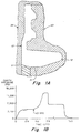
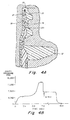
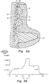
- Figs. 1-7 In an attempt to better understand the backflow problem, a series of short shots were performed to illustrate what happens during the end of the filling stage, and during the packing and cooling stage. These short shots are illustrated in Figs. 1-7, and include a series of preform neck finish cross sections and related pressure versus time graphs. Each of Figs. 1B-7B shows the same pressure/time cycle, with a movable arrow indicating the time in the cycle at which the preform cross section (shown above in Figs. 1A-7A) was evaluated.
- the pressure/time curve of Figs. 1-7 is typical for CPT's sequential injection molding process for making a five-layer PET/EVOH container wherein: a first shot of virgin PET forms exterior inner and outer layers of the preform; a second shot of EVOH forms first and second intermediate barrier layers adjacent the inner and outer layers; and a third shot of virgin or recycled PET forms a central core layer between the intermediate layers.
- the cavity pressure increases rapidly during the initial portion of the first shot and then levels off at about 4000 psi for the remainder of the 5.5 second filling time.
- the second and third shots are substantially below this point and not visible in Fig. 1A.
- a second flow front 16 (EVOH) is just reaching the lowermost end 11 of the flange, followed by a third flow front 17 (of virgin or recycled PET).
- the first shot has formed inner and outer layers (20, 21) throughout substantially all of the neck finish, and filled the flange 12.
- a second flow front 22 (EVOH) is nearing a top sealing surface 13 of the preform, but has not broken through the first shot.
- a third flow front 23 (PET) is close behind the second shot. There are some corners 25-28 of the neck finish which have not yet been filled. It should be understood in Figs. 2-8 that lines 18, 19 represent the inner intermediate and outer intermediate second shot (EVOH) material layers in the preform, respectively, which surround a central core layer 30 of the third shot (PET) material.
- the first shot has completely filled all areas of contact with the core and cavity walls, and the second and third shots (layers 18, 19, 30) extend substantially vertically throughout the neck finish without penetrating the top sealing surface 13.
- the holding pressure is intended to maintain the preform in contact with the cold mold cavity and core walls, and therefore the inner and outer preform layers (20, 21) are cooler than the interior second (18, 19) and third (30) shot layers. If the second and third shots are still molten, they seek a flow path of least resistance which in this case is back down towards the flange 12 (where the greatest amount of contraction is occurring in the outer layer).
- a spill over or fingering portion 40 forms at the terminal end including both of the second and third shot layers; the fingering portion, which is the initiation of backflow, is directed radially outwardly and back down towards the flange.
- the tapered neck region in the preform mold has a surprising affect on what may be considered, a relatively minor leading edge effect caused for example by a misalignment between the core and cavity.
- a relatively small leading edge effect may develop in the first flow front (caused by core misalignment), prior to reaching the tapered region.
- the first flow front advances through the tapered region, there is an increase in the velocity of the flow which causes an increased circumferential flow of material from the leading to the trailing edge at the first flow front.
- Fig. 9 shows an exemplary ketchup container 50 having an upper neck finish 51, a long and thin neck 52, a sidewall 53, and a base 54.
- the neck finish includes threads 55 and a lowermost support ring or flange 56.
- a preform is used, such as that shown in Figs. 10-12, having a tapered neck region 82. Because the long and thin container neck 52 undergoes relatively little radial stretch, it is necessary to enhance the axial stretch in order to achieve the necessary biaxial orientation (and resulting mechanical strength) in the neck 52.
- a tapered neck region is provided in the preform which decreases in wall thickness going towards the neck finish 81(see Fig. 12); the decrease in wall thickness is achieved by reducing the diameter of the outer wall 85 as it approaches the neck finish.
- the reduced thickness portion of the neck region is caused to undergo greater axial stretch during the initial axial elongation of the preform (because it is thinner than the remaining sidewall and outer base portions and thus easier to stretch).
- an upper portion 95 undergoes relatively greater axial stretch than a lower portion 96, because of the tapering wall thickness.
- Fig. 10 shows one potential cause of a leading edge effect, namely a misalignment of the core and cavity.
- Core shift is a common phenomenon that occurs to some degree in all injection tools -- single or multicavity, mono or multilayer.
- Fig. 10A is a cross-section along the length of the preform mold 60.
- a core 58 is positioned in an outer cavity to define a space for molding a preform between the core wall 61 and cavity wall 62.
- a misalignment of the core and cavity is illustrated at a circumference 59 near the lower end of the preform, which is illustrated in cross-section in Fig. 10B.
- the core is shifted slightly to the left, so that the distance between the core wall and cavity wall on the right side (t a ) is greater than the distance between the core wall 61 and cavity wall 62 on the left side (t b ).
- Container manufacturers impose limits on the maximum wall variation in the preform, which is defined by: ⁇ a 2 + b 2 , the minimum and maximum radial wall thicknesses.
- leading edge effect Other potential causes of a leading edge effect include nonsymmetric cooling, i.e., temperature differences at various points along the core and cavity walls, and melt non-uniformity, i.e., polymer temperature differences due to variations in the hot runner system.
- nonsymmetric cooling i.e., temperature differences at various points along the core and cavity walls
- melt non-uniformity i.e., polymer temperature differences due to variations in the hot runner system.
- core/cavity misalignment has now been identified as a primary cause of the leading edge effect in sequential co-injection.
- Fig. 11 illustrates schematically the preform mold cavity defined by core wall 61 and cavity wall 62, and an injection nozzle 65 for sequentially injecting different polymer materials into a gate 66 at the bottom of the preform mold.
- first shot material 70 is injected from a central channel 67 in the nozzle, and flows about halfway up the preform wall.
- any leading edge difference in the first shot is very small, i.e., about 1 mm, when it reaches the upper end of the sidewall, at the lower boundary 63 of the tapered neck region. Furthermore, when examining short shots it has been found that this small difference does not increase as the first shot proceeds up through the tapered region to the upper boundary 64.
- the second (barrier) shot 72 also does not require complex equipment or process controls.
- sequential molding it is possible to introduce the barrier melt through an unbalanced and non-concentric single drill channel 68, as shown in Fig. 11.
- the flow resistance provided by the virgin PET (first shot) already in the cavity forces the barrier material to form a circumferentially-balanced, disk-like melt pool within the frozen PET skin layers.
- This "self-leveling" feature of sequential injection means there is substantially no leading edge effect due to introduction of the materials into the mold cavity.
- a third shot of virgin or recycled PET can be injected via offset channel 69, and likewise forms a self-leveling melt pool, which subsequently pushes the first and second shots ahead of it to fill the mold.
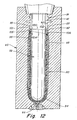
- Fig. 12 shows the first, second and third shot layers as they are moving up through the tapered region.
- the preform profile 80 is defined by the core wall 61 and cavity wall 62, and includes the neck finish 81, tapered region 82, sidewall 83 and base 84.
- the first shot material has a first flow front 100 with a difference in height of the advancing front (as measured from the bottom of the preform) between upper point 101 (on the left) and lower point 102 (on the right), at different points on the circumference.
- a second shot material with second flow front 104 has developed an enhanced difference between upper point 105 (on the left) and lower point 106 (on the right).
- the second front 104 is developing a larger edge effect (greater difference between leading and trailing points) around the circumference than the first front 100.
- Figure 13 is a lengthwise cross-section showing a melt front 90 across a width of a preform having a leading point 91 at the center of a vertical axis 97 and trailing points 92, 93 at each of the outer side edges of the melt front.
- the melt front direction is represented by a number of parallel vertical arrows 94 pointing up. Because of the leading point/trailing point difference, the velocity of the melt front is not parallel to the melt flow direction, but rather at an angle thereto. As shown, the velocity of the melt (V melt ) has both an axial component (V axial ) and a circumferential component (V cir ).
- the circumferential component causes material to flow circumferentially in the cavity, transverse to the filling direction.
- the first shot of virgin PET may develop a leading edge effect as it moves up the injection cavity due to nonsymmetric conditions that may exist in the system, such as the lack of concentricity between the core and cavity walls, nonsymmetric temperature conditions, etc.
- the circumferential component of the melt velocity causes the virgin PET in the vicinity of the leading point to flow toward the trailing point.
- Such a circumferential flow would increase the size of the melt pool in front (ahead) of the second and third melt fronts in line (circumferentially) with the first front trailing point, and at the same time, decrease it ahead of the second and third melt fronts in line (circumferentially) with the first front leading point.
- the circumferential flow of the first material would thus reduce the difference between the leading and trailing points in the first flow front, and thus reduce the edge effect in the first flow front. However, it has the opposite effect on the second and subsequent flow fronts. Because of the transfer of material circumferentially, there would be an unbalanced circumferential flow ahead of the second (and subsequent) flow front which may cause or enhance a leading edge effect in the second (and subsequent) flow front.
- the width of the tapered region has a substantial effect on the development of a leading edge effect in the second flow front. It has been found that increasing the minimum width in this tapered neck region, within the limits allowed by the desired preform/container axial stretch ratios, has a substantial affect on reducing development of a leading edge effect in the second or subsequent flow fronts.
- Adjusting the minimum wall thickness of the tapered neck region can substantially reduce or eliminate the problem.
- it may not be possible to completely eliminate backflow because the thickness of the tapered neck region would be too great to provide the necessary axial stretch in a corresponding portion of the blow-molded container.
- backflow can be reduced by increasing the tapered neck region wall thickness to the extent possible.
- TSS top sealing surface
- Figs. 14A-14C show schematically in side plan and cross-sectional views a neck finish 103 in which a minimal amount of backflow has occurred (see backflow 109a), and there is a substantial distance d 1 between the top 107a of the internal EVOH barrier layer and the TSS 108.
- d 1 1.0mm and there has been no backflow into the flange 110.
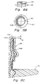
- Figs. 15A-17A, 15B-17B and 15C-17C are similar to Figs. 14A, 14B and 14C respectively, but with increasing amounts of barrier layer backflow (109b-109d) which not only structurally weaken the neck finish, but cause the top (107b-107d) of the EVOH barrier layer to approach the TSS.
- the EVOH has backflowed (109b) into the flangc, at greater than 180° but less than 270° around the flange, and the distance d 1 from the top sealing surface is reduced to about 0.4mm. This still enables formation of an effective heat seal.
- Fig. 15A-17A, 15B-17B and 15C-17C are similar to Figs. 14A, 14B and 14C respectively, but with increasing amounts of barrier layer backflow (109b-109d) which not only structurally weaken the neck finish, but cause the top (107b-107d) of the EVOH barrier layer to approach the TSS.
- the EVOH has backflowed (109b
- the EVOH has backflowed (109c) further into the flange and the distance d 3 now extends about 320° around the flange, and has approached to within 0.1mm of the top sealing surface. This distance is the minimum for an acceptable seal.
- the EVOH barrier has backflowed (109d) such that it extends completely around the full 360° flange, and the distance d 4 is less than 0.1mm; this is too close to the TSS and will lead to inevitable seal failures.
- Fig. 18 is an enlarged cross-section of a neck finish with a heat-bonded seal and cap, according to one embodiment. More specifically, a neck finish 120 has a TSS 122, with a heat-bonded laminated foil liner or seal 124. The liner 124 lies within an inner surface of a cap 126. The liner 124 is intended to ensure a tight seal to prevent leakage, in the event there is any deformation in the neck finish.
- Fig. 19 shows an alternative low-height neck finish 130.
- the height of the finish reduced but there are no threads on the upper neck finish portion 131, and there is no lowermost flange.
- a radially indented groove 133 is provided, which is engaged by a projection 135 on a snap-fit cap 136.
- a foil liner 134 is heat bonded to a top sealing surface 132 of the neck finish.
- the present invention has many potential applications for preventing significant leading edge effects which cause backflow or sealing defects in a multilayer article, including preforms and stretch blow-molded containers.
- recycled PET has a larger color component than virgin PET, it has been found that the recycled PET heats more quickly (i.e., during the reheat process, prior to blow molding). If there is a circumferential difference in the final flow front of the recycled PET layer, the circumferential imbalance may lead to a circumferential imbalance in the heating of the layer and a resulting imbalance in the amount of stretching during blow molding.
- Another problem which may result from an uneven circumferential distribution of a polymer layer in a preform or container is a visual "lensing" effect which renders the preform/container unacceptable.
- a difference in a barrier (e.g., EVOH) flow front may produce an oriented bottle wall with a visual distortion or defect in the oriented neck region.
- one or more layers of the preform and container, or portions thereof can be made of various polyesters and various other polymers, such as polyolefins (e.g., polypropylene and polyethylene), polyvinyl chloride, polyacrylate, etc.
- Suitable polyesters include homopolymers, copolymers or blends of polyethylene terephthalate (PET), polybutylene terephthalate (PBT), polypropylene terephthalate (PPT), polyethylene naphthalate (PEN), and a cyclohexane dimethanol/PET copolymer, known as PETG (available from Eastman Chemical Company, Kingsport, Tennessee).
- Polyesters based on terephthalic or isophthalic acid are commercially available and convenient.
- the hydroxy compounds are typically ethylene glycol and 1,4-di-(hydroxy methyl)-cyclohexane.
- the phthalate polyester may include polymer linkages, side chains, and end groups not related to the formal precursors of a simple phthalate polyester previously specified.
- at least 90 mole percent will be terephthalic acid and at least 90 mole percent an aliphatic glycol or glycols, especially ethylene glycol.
- PC-PET Recycled or post-consumer PET
- PC-PET is prepared from PET plastic containers and other recyclables that are returned by consumers for a recycling operation, and has now been approved by the FDA for use in certain food containers.
- PC-PET is known to have a certain level of I.V. (intrinsic viscosity), moisture content, and contaminants.
- I.V. intrinsic viscosity
- typical PC-PET having a flake size of one-half inch maximum
- PEN polyethylene naphthalate
- PEN provides a 3-5X improvement in barrier property and enhanced thermal resistance, at some additional expense.
- Polyethylene naphthalate (PEN) is a polyester produced when dimethyl 2,6-naphthalene dicarboxylate (NDC) is reacted with ethylene glycol.
- NDC dimethyl 2,6-naphthalene dicarboxylate
- the PEN polymer comprises repeating units of ethylene 2,6 naphthalate.
- PEN resin is available having an inherent viscosity of 0.67dl/g and a molecular weight of about 20,000 from Amoco Chemical Company, Chicago, Illinois.
- PEN has a glass transition temperature T g of about 123°C, and a melting temperature T m of about 267°C.
- PET and PEN may be blended or copolymerizcd in various amounts. In the ranges of about 0-20% PEN and 80-100% PEN, the material may be crystallized, while from about 20-80% PEN the material can not be crystallized and remains substantially amorphous.
- PET and PEN The structures of PET and PEN are shown below:
- Suitable polyamides include PA6, PA6,6, PA6,4, PA6,10, PA11, PA12, etc.
- Other options include acrylic/amide, amorphous nylon, polyacrylonitrile (PAN), polystyrene, crystallizable nylon (MXD-6), polyethylene (PE), polypropylene (PP), and polyvinyl chloride (PVC).
- the multilayer preform/container may also include one or more layers of an oxygen barrier material such as ethylene/vinyl alcohol (EVOH), PEN, polyvinyl alcohol (PVOH), polyvinyldene chloride (PVDC), nylon 6, crystallizable nylon (MXD-6), LCP (liquid crystal polymer), amorphous nylon, polyacrylonitrile (PAN) and styrene acrylonitrile (SAN).
- an oxygen barrier material such as ethylene/vinyl alcohol (EVOH), PEN, polyvinyl alcohol (PVOH), polyvinyldene chloride (PVDC), nylon 6, crystallizable nylon (MXD-6), LCP (liquid crystal polymer), amorphous nylon, polyacrylonitrile (PAN) and styrene acrylonitrile (SAN).
- EVOH ethylene/vinyl alcohol
- PEN polyvinyl alcohol
- PVDC polyvinyldene chloride
- MXD-6 crystallizable nylon
- LCP liquid crystal
- the intrinsic viscosity (I.V.) effects the processability of the resins.
- Polyethylene terephthalate having an intrinsic viscosity of about 0.8 is widely used in the carbonated soft drink (CSD) industry.
- Polyester resins for various applications may range from about 0.55 to about 1.04, and more particularly from about 0.65 to 0.85dl/g.
- Intrinsic viscosity measurements of polyester resins are made according to the procedure of ASTM D-2857, by employing 0.0050 ⁇ 0.0002 g/ml of the polymer in a solvent comprising o-chlorophenol (melting point 0°C), respectively, at 30°C.
- the blown container body in one embodiment is substantially transparent.
- the diffuse and specular light transmission values are measured in accordance with ASTM Method D 1003, using any standard color difference meter such as model D25D3P manufactured by Hunterlab, Inc.
- the container body in this embodiment should have a percent haze (through the panel wall) of less than about 10%, and more preferably less than about 5%.
- the preform body-forming portion in this embodiment should also be substantially amorphous and transparent, having a percent haze across the wall of no more than about 10%, and more preferably no more than about 5%.
- the container will have varying levels of crystallinity at various positions along the height of the bottle from the neck finish to the base.
- the panel or sidewall portion 53 of the container is stretched the greatest and preferably has an average percent crystallinity of at least about 10%, and more preferably at least about 15%.
- the percent crystallinity in the neck region 52 is preferably 5-10%.
- Crystallinity can be achieved by heat setting to provide a combination of strain-induced and thermal-induced crystallization.
- Thermal-induced crystallinity is achieved at low temperatures to preserve transparency, e.g., holding the container in contact with a low temperature blow mold. In some applications, a high level of crystallinity at the surface of the sidewall alone is sufficient.
- the preform may include one or more layers of an oxygen-scavenging material.
- suitable oxygen- scavenging materials are described in U.S. Serial No. 08/355,703 filed December 14, 1994 by Collette et al., entitled "Oxygen Scavenging Composition For Multilayer Preform And Container,” which is hereby incorporated by reference in its entirety.
- the oxygen scavenger may be a metal-catalyzed oxidizable organic polymer, such as a polyamide.
- the oxygen scavenger may be mixed with PC-PET to accelerate activation of the scavenger.
- the oxygen scavenger may be advantageously combined with other thermoplastic polymers to provide the desired injection molding and stretch blow molding characteristics for making substantially amorphous injection molded preforms and substantially transparent biaxially- oriented polyester containers.
- the oxygen scavenger may be provided as an interior layer to retard migration of the oxygen scavenger or its byproducts, and to prevent premature activation of the scavenger.
Landscapes
- Manufacturing & Machinery (AREA)
- Mechanical Engineering (AREA)
- Engineering & Computer Science (AREA)
- Blow-Moulding Or Thermoforming Of Plastics Or The Like (AREA)
- Injection Moulding Of Plastics Or The Like (AREA)
- Processing And Handling Of Plastics And Other Materials For Molding In General (AREA)
- Moulds For Moulding Plastics Or The Like (AREA)
- Laminated Bodies (AREA)
- Biological Depolymerization Polymers (AREA)
- Sealing Material Composition (AREA)
- Wrappers (AREA)
- Polymerisation Methods In General (AREA)
- Auxiliary Devices For And Details Of Packaging Control (AREA)
- Packages (AREA)
Applications Claiming Priority (3)
| Application Number | Priority Date | Filing Date | Title |
|---|---|---|---|
| US08/702,755 US6063325A (en) | 1996-08-22 | 1996-08-22 | Method for preventing uncontrolled polymer flow in preform neck finish during packing and cooling stage |
| US702755 | 1996-08-22 | ||
| EP97938361A EP0921928B1 (de) | 1996-08-22 | 1997-08-18 | Verfahren zum vermeiden von unkontrollierten polymerströmen im vorformhals beim verdichtungs- und kühlvorgang |
Related Parent Applications (1)
| Application Number | Title | Priority Date | Filing Date |
|---|---|---|---|
| EP97938361A Division EP0921928B1 (de) | 1996-08-22 | 1997-08-18 | Verfahren zum vermeiden von unkontrollierten polymerströmen im vorformhals beim verdichtungs- und kühlvorgang |
Publications (2)
| Publication Number | Publication Date |
|---|---|
| EP1215028A2 true EP1215028A2 (de) | 2002-06-19 |
| EP1215028A3 EP1215028A3 (de) | 2003-01-02 |
Family
ID=24822455
Family Applications (2)
| Application Number | Title | Priority Date | Filing Date |
|---|---|---|---|
| EP97938361A Expired - Lifetime EP0921928B1 (de) | 1996-08-22 | 1997-08-18 | Verfahren zum vermeiden von unkontrollierten polymerströmen im vorformhals beim verdichtungs- und kühlvorgang |
| EP02075822A Withdrawn EP1215028A3 (de) | 1996-08-22 | 1997-08-18 | Verfahren zum Verhinderen eines unkontrollierten Polymerstromes in einem Vorformhals während der Nachdrück- und Kühlungsstufe |
Family Applications Before (1)
| Application Number | Title | Priority Date | Filing Date |
|---|---|---|---|
| EP97938361A Expired - Lifetime EP0921928B1 (de) | 1996-08-22 | 1997-08-18 | Verfahren zum vermeiden von unkontrollierten polymerströmen im vorformhals beim verdichtungs- und kühlvorgang |
Country Status (16)
| Country | Link |
|---|---|
| US (1) | US6063325A (de) |
| EP (2) | EP0921928B1 (de) |
| JP (1) | JP4104022B2 (de) |
| CN (2) | CN1159147C (de) |
| AT (1) | ATE227632T1 (de) |
| AU (1) | AU727103B2 (de) |
| BR (1) | BR9711343A (de) |
| CA (1) | CA2263845C (de) |
| DE (1) | DE69717119T2 (de) |
| DK (1) | DK0921928T3 (de) |
| ES (1) | ES2187808T3 (de) |
| HU (1) | HUP9903957A3 (de) |
| NO (1) | NO313817B1 (de) |
| NZ (1) | NZ334575A (de) |
| PT (1) | PT921928E (de) |
| WO (1) | WO1998007556A1 (de) |
Cited By (2)
| Publication number | Priority date | Publication date | Assignee | Title |
|---|---|---|---|---|
| EP1997603A1 (de) * | 2007-05-31 | 2008-12-03 | Alliance for business solutions A4BS | Modifizierte Heißkanalsysteme zum Spritz-Blasformen |
| US8715563B2 (en) | 2009-11-30 | 2014-05-06 | Alliance For Business Solutions A4Bs | Modified hot runner systems for injection blow molding |
Families Citing this family (42)
| Publication number | Priority date | Publication date | Assignee | Title |
|---|---|---|---|---|
| US6123211A (en) * | 1997-10-14 | 2000-09-26 | American National Can Company | Multilayer plastic container and method of making the same |
| DE69929055T2 (de) * | 1998-05-01 | 2006-07-20 | Duramed Pharmaceuticals Inc., Cincinnati | Verfahren zur spritzgussherstellung von vorrichtungen mit kontrollierter wirkstofffreisetzung und damit hergestellte vorrichtung |
| US7543713B2 (en) | 2001-04-19 | 2009-06-09 | Graham Packaging Company L.P. | Multi-functional base for a plastic, wide-mouth, blow-molded container |
| JP3896524B2 (ja) * | 2000-12-20 | 2007-03-22 | 株式会社吉野工業所 | 合成樹脂製2軸延伸ブロー成形壜体成形用プリフォーム |
| US20030161977A1 (en) * | 2001-04-06 | 2003-08-28 | Douglas Sabin | Four layer nozzle for forming four layer articles |
| US6908581B2 (en) * | 2001-04-06 | 2005-06-21 | Kortec, Inc. | Optimized flow to prevent core layer breakthrough |
| US6596213B2 (en) * | 2001-04-06 | 2003-07-22 | Kortec, Inc. | Method of molding multi-layer polymer plastic articles with control of relative shifting of the core layer |
| JP2004532756A (ja) * | 2001-06-18 | 2004-10-28 | ベクトン・ディキンソン・アンド・カンパニー | 多層容器および多層容器の形成方法 |
| JP3994146B2 (ja) * | 2001-12-18 | 2007-10-17 | 株式会社吉野工業所 | 合成樹脂製容器本体およびプリフォームの金型装置 |
| WO2003064133A1 (en) * | 2002-01-31 | 2003-08-07 | Kortec, Inc. | Optimized flow to prevent core layer breakthrough |
| ATE390383T1 (de) | 2003-07-30 | 2008-04-15 | Graham Packaging Co | Behälterhandhabungssystem |
| CA2573139C (en) * | 2004-07-07 | 2015-08-25 | Kortec, Inc. | Multilayer molding using temperature adjustment of flow rate in conjunction with shooting pot technology |
| US8017065B2 (en) | 2006-04-07 | 2011-09-13 | Graham Packaging Company L.P. | System and method for forming a container having a grip region |
| US8857637B2 (en) | 2006-03-06 | 2014-10-14 | Plastipak Packaging, Inc. | Lightweight plastic container and preform |
| US10457437B2 (en) | 2006-03-06 | 2019-10-29 | Plastipak Packaging, Inc. | Lightweight plastic container and preform |
| US8747727B2 (en) | 2006-04-07 | 2014-06-10 | Graham Packaging Company L.P. | Method of forming container |
| US9707711B2 (en) | 2006-04-07 | 2017-07-18 | Graham Packaging Company, L.P. | Container having outwardly blown, invertible deep-set grips |
| EP1955835A1 (de) | 2007-02-07 | 2008-08-13 | Aisapack Holding SA | Verfahren zur Herstellung eines mehrschichtigen Objekts |
| US20090223920A1 (en) * | 2008-03-07 | 2009-09-10 | Graham Packaging Company, Lp | Abuse resistant preform and container neck finish |
| US8627944B2 (en) | 2008-07-23 | 2014-01-14 | Graham Packaging Company L.P. | System, apparatus, and method for conveying a plurality of containers |
| US8597748B2 (en) * | 2008-09-02 | 2013-12-03 | Graham Packaging Company, L.P. | Preform for making plastic container |
| US8636944B2 (en) * | 2008-12-08 | 2014-01-28 | Graham Packaging Company L.P. | Method of making plastic container having a deep-inset base |
| US7926243B2 (en) | 2009-01-06 | 2011-04-19 | Graham Packaging Company, L.P. | Method and system for handling containers |
| WO2011112613A1 (en) * | 2010-03-08 | 2011-09-15 | Kortec, Inc. | Methods of molding multi-layer polymeric articles having control over the breakthrough of the core layer |
| GB2478732B (en) | 2010-03-15 | 2014-08-20 | Kraft Foods R & D Inc | Improvements in injection moulding |
| PL2593285T3 (pl) * | 2010-07-16 | 2019-08-30 | Milacron Llc | Ulepszona nieprzepuszczalność gazowa pojemników formowanych wtryskowo |
| US8580294B2 (en) | 2010-10-19 | 2013-11-12 | International Partnership For Microbicides | Platinum-catalyzed intravaginal rings |
| US8962114B2 (en) | 2010-10-30 | 2015-02-24 | Graham Packaging Company, L.P. | Compression molded preform for forming invertible base hot-fill container, and systems and methods thereof |
| JP6035609B2 (ja) * | 2010-11-24 | 2016-11-30 | ミラクロン エルエルシー | ヒートシール欠陥の防止方法および製品 |
| US9994378B2 (en) | 2011-08-15 | 2018-06-12 | Graham Packaging Company, L.P. | Plastic containers, base configurations for plastic containers, and systems, methods, and base molds thereof |
| US9150320B2 (en) | 2011-08-15 | 2015-10-06 | Graham Packaging Company, L.P. | Plastic containers having base configurations with up-stand walls having a plurality of rings, and systems, methods, and base molds thereof |
| US8919587B2 (en) | 2011-10-03 | 2014-12-30 | Graham Packaging Company, L.P. | Plastic container with angular vacuum panel and method of same |
| CH707196A1 (de) * | 2012-11-07 | 2014-05-15 | Alpla Werke | Spritzgegossener Preform zur Herstellung von Kunststoffbehältern in einem Streckblasverfahren. |
| US9022776B2 (en) | 2013-03-15 | 2015-05-05 | Graham Packaging Company, L.P. | Deep grip mechanism within blow mold hanger and related methods and bottles |
| US9254937B2 (en) | 2013-03-15 | 2016-02-09 | Graham Packaging Company, L.P. | Deep grip mechanism for blow mold and related methods and bottles |
| US10137031B2 (en) | 2013-11-14 | 2018-11-27 | International Partnership For Microbicides, Inc. | Combination therapy intravaginal rings |
| DE102014004221A1 (de) | 2014-03-25 | 2015-10-01 | Hpt Hochwertige Pharmatechnik Gmbh & Co. Kg | Spritzstation für die Herstellung von Multilayer-Vorformlingen |
| US10583602B2 (en) * | 2016-03-11 | 2020-03-10 | Ring Container Technologies, Llc | Container and method of manufacture |
| JP6870079B2 (ja) * | 2016-10-05 | 2021-05-12 | ハスキー インジェクション モールディング システムズ リミテッドHusky Injection Molding Systems Limited | マルチ材料ホットランナーノズル |
| CH716662A1 (de) * | 2019-10-02 | 2021-04-15 | Alpla Werke Alwin Lehner Gmbh & Co Kg | Wiederbefüllbarer Kunststoffbehälter mit einem Hals mit einer Halsöffnung und einen ein Füllvolumen umschliessenden Behälterkörper. |
| CN112223725B (zh) * | 2020-09-23 | 2022-06-28 | 四川科伦药业股份有限公司 | 一种塑料输液容器注吹一体制造方法 |
| CN117565332B (zh) * | 2023-12-22 | 2024-06-11 | 太仓市众翔精密五金有限公司 | 一种二次成型模具注射流道结构及注塑成型装置 |
Family Cites Families (9)
| Publication number | Priority date | Publication date | Assignee | Title |
|---|---|---|---|---|
| US4332545A (en) * | 1977-12-23 | 1982-06-01 | Emhart Industries, Inc. | Core pin support and adjusting arrangement |
| US4627952A (en) * | 1982-09-03 | 1986-12-09 | Celanese Corporation | Injection molding process |
| US4554190A (en) * | 1983-04-13 | 1985-11-19 | American Can Company | Plastic containers with folded-over internal layers and methods for making same |
| US4609516A (en) * | 1984-02-17 | 1986-09-02 | Continental Pet Technologies, Inc. | Method of forming laminated preforms |
| US4550043A (en) * | 1984-02-17 | 1985-10-29 | Continental Plastic Containers, Inc. | Preform with internal barrier and internal layer of high thermal stability and products made from the same |
| US4847129A (en) * | 1988-09-16 | 1989-07-11 | Continental Pet Technologies, Inc. | Multilayer preform for hot fill containers |
| US4954376A (en) * | 1988-12-30 | 1990-09-04 | Continental Pet Technologies, Inc. | Two material three/five layer preform |
| US5539675A (en) * | 1993-12-30 | 1996-07-23 | General Electric Company | Automated thickness measuring device |
| US5464106A (en) * | 1994-07-06 | 1995-11-07 | Plastipak Packaging, Inc. | Multi-layer containers |
-
1996
- 1996-08-22 US US08/702,755 patent/US6063325A/en not_active Expired - Fee Related
-
1997
- 1997-08-18 BR BR9711343A patent/BR9711343A/pt not_active IP Right Cessation
- 1997-08-18 CN CNB011238941A patent/CN1159147C/zh not_active Expired - Fee Related
- 1997-08-18 HU HU9903957A patent/HUP9903957A3/hu unknown
- 1997-08-18 WO PCT/US1997/014451 patent/WO1998007556A1/en not_active Ceased
- 1997-08-18 JP JP51084698A patent/JP4104022B2/ja not_active Expired - Fee Related
- 1997-08-18 CA CA002263845A patent/CA2263845C/en not_active Expired - Fee Related
- 1997-08-18 DK DK97938361T patent/DK0921928T3/da active
- 1997-08-18 CN CN97198668A patent/CN1082427C/zh not_active Expired - Fee Related
- 1997-08-18 NZ NZ334575A patent/NZ334575A/xx unknown
- 1997-08-18 EP EP97938361A patent/EP0921928B1/de not_active Expired - Lifetime
- 1997-08-18 EP EP02075822A patent/EP1215028A3/de not_active Withdrawn
- 1997-08-18 AT AT97938361T patent/ATE227632T1/de not_active IP Right Cessation
- 1997-08-18 AU AU40710/97A patent/AU727103B2/en not_active Ceased
- 1997-08-18 DE DE69717119T patent/DE69717119T2/de not_active Expired - Fee Related
- 1997-08-18 PT PT97938361T patent/PT921928E/pt unknown
- 1997-08-18 ES ES97938361T patent/ES2187808T3/es not_active Expired - Lifetime
-
1999
- 1999-02-22 NO NO19990826A patent/NO313817B1/no unknown
Cited By (7)
| Publication number | Priority date | Publication date | Assignee | Title |
|---|---|---|---|---|
| EP1997603A1 (de) * | 2007-05-31 | 2008-12-03 | Alliance for business solutions A4BS | Modifizierte Heißkanalsysteme zum Spritz-Blasformen |
| WO2008145746A1 (en) * | 2007-05-31 | 2008-12-04 | Alliance For Business Solutions A4Bs | Modified hot runner system s for injection blow molding |
| RU2479425C2 (ru) * | 2007-05-31 | 2013-04-20 | Альянс фо Бизнес Солюшнз А4БС | Модифицированные системы горячих литниковых каналов для инжекционно-выдувного формования |
| MD4309C1 (ro) * | 2007-05-31 | 2015-06-30 | Alliance For Business Solutions A4Bs | Procedee de formare prin injecţie-suflare pentru fabricarea unui recipient, semifabricate pentru recipiente, recipient şi aplicarea acestuia |
| US8715563B2 (en) | 2009-11-30 | 2014-05-06 | Alliance For Business Solutions A4Bs | Modified hot runner systems for injection blow molding |
| US10106646B2 (en) | 2009-11-30 | 2018-10-23 | Keiryo Packaging Sa | Modified hot runner systems for injection blow molding |
| US10954337B2 (en) | 2009-11-30 | 2021-03-23 | Keiryo Packaging Sa | Modified hot runner systems for injection blow molding |
Also Published As
| Publication number | Publication date |
|---|---|
| CA2263845A1 (en) | 1998-02-26 |
| NO313817B1 (no) | 2002-12-09 |
| CA2263845C (en) | 2006-12-05 |
| BR9711343A (pt) | 1999-08-17 |
| JP2000516167A (ja) | 2000-12-05 |
| HUP9903957A2 (hu) | 2001-09-28 |
| AU727103B2 (en) | 2000-11-30 |
| CN1082427C (zh) | 2002-04-10 |
| EP1215028A3 (de) | 2003-01-02 |
| WO1998007556A1 (en) | 1998-02-26 |
| NO990826D0 (no) | 1999-02-22 |
| ATE227632T1 (de) | 2002-11-15 |
| EP0921928B1 (de) | 2002-11-13 |
| AU4071097A (en) | 1998-03-06 |
| JP4104022B2 (ja) | 2008-06-18 |
| CN1233207A (zh) | 1999-10-27 |
| CN1159147C (zh) | 2004-07-28 |
| US6063325A (en) | 2000-05-16 |
| DE69717119T2 (de) | 2003-08-21 |
| ES2187808T3 (es) | 2003-06-16 |
| EP0921928A1 (de) | 1999-06-16 |
| PT921928E (pt) | 2003-03-31 |
| DE69717119D1 (de) | 2002-12-19 |
| DK0921928T3 (da) | 2003-03-10 |
| NZ334575A (en) | 2000-10-27 |
| CN1377765A (zh) | 2002-11-06 |
| HUP9903957A3 (en) | 2001-10-29 |
| NO990826L (no) | 1999-04-21 |
Similar Documents
| Publication | Publication Date | Title |
|---|---|---|
| EP0921928B1 (de) | Verfahren zum vermeiden von unkontrollierten polymerströmen im vorformhals beim verdichtungs- und kühlvorgang | |
| CA2248106C (en) | Multilayer container resistant to elevated temperatures and pressures, and method of making the same | |
| CA2226230C (en) | Sleeve molding | |
| EP1147872B1 (de) | Verfahren zum Formen von mehrschichtigen Kunststoffgegenständen | |
| AU674528B2 (en) | Method of forming multi-layer preform and container with low crystallizing interior layer | |
| EP0734316B2 (de) | Mehrschichtiger vorformling und behälter aus polyäthylennaphtalat (pen) und dessen herstellungsverfahren | |
| US5902539A (en) | Process for making PEN/PET blends and transparent articles therefrom | |
| CA2183203A1 (en) | Process for injection molding a preform of a polyester resin, injection screw and process for stretch blow molding the same | |
| AU2003277521B2 (en) | Preform, process for producing the same, and biaxially drawn container made from the preform | |
| MXPA99001762A (en) | Method for preventing uncontrolled polymer flow in preform neck finish during packing and cooling stage | |
| CA2436981A1 (en) | Sleeve molding | |
| JPH01214423A (ja) | 延伸ブローポリエステル容器及びその製法 | |
| MXPA96003357A (en) | Process to mold by injection a preform of a polyester resin, a screw of injection and process to mold by stretched by blowing lami |
Legal Events
| Date | Code | Title | Description |
|---|---|---|---|
| PUAI | Public reference made under article 153(3) epc to a published international application that has entered the european phase |
Free format text: ORIGINAL CODE: 0009012 |
|
| 17P | Request for examination filed |
Effective date: 20020301 |
|
| AC | Divisional application: reference to earlier application |
Ref document number: 921928 Country of ref document: EP |
|
| AK | Designated contracting states |
Kind code of ref document: A2 Designated state(s): AT BE CH DE DK ES FI FR GB GR IE IT LI LU MC NL PT SE |
|
| PUAL | Search report despatched |
Free format text: ORIGINAL CODE: 0009013 |
|
| AK | Designated contracting states |
Kind code of ref document: A3 Designated state(s): AT BE CH DE DK ES FI FR GB GR IE IT LI LU MC NL PT SE |
|
| AKX | Designation fees paid |
Designated state(s): AT BE CH DE DK ES FI FR GB GR IE IT LI LU MC NL PT SE |
|
| 17Q | First examination report despatched |
Effective date: 20040802 |
|
| RAP1 | Party data changed (applicant data changed or rights of an application transferred) |
Owner name: GRAHAM PACKAGING PET TECHNOLOGIES INC. |
|
| GRAP | Despatch of communication of intention to grant a patent |
Free format text: ORIGINAL CODE: EPIDOSNIGR1 |
|
| STAA | Information on the status of an ep patent application or granted ep patent |
Free format text: STATUS: THE APPLICATION IS DEEMED TO BE WITHDRAWN |
|
| 18D | Application deemed to be withdrawn |
Effective date: 20090303 |