EP1215079A1 - Fixation de housses pour sièges de véhicule - Google Patents
Fixation de housses pour sièges de véhicule Download PDFInfo
- Publication number
- EP1215079A1 EP1215079A1 EP00311250A EP00311250A EP1215079A1 EP 1215079 A1 EP1215079 A1 EP 1215079A1 EP 00311250 A EP00311250 A EP 00311250A EP 00311250 A EP00311250 A EP 00311250A EP 1215079 A1 EP1215079 A1 EP 1215079A1
- Authority
- EP
- European Patent Office
- Prior art keywords
- cord
- channel
- fastening means
- male
- female
- Prior art date
- Legal status (The legal status is an assumption and is not a legal conclusion. Google has not performed a legal analysis and makes no representation as to the accuracy of the status listed.)
- Granted
Links
- 239000000463 material Substances 0.000 claims abstract description 4
- 239000002991 molded plastic Substances 0.000 claims abstract description 3
- 229920006324 polyoxymethylene Polymers 0.000 claims description 6
- 229930040373 Paraformaldehyde Natural products 0.000 claims description 4
- 229920000139 polyethylene terephthalate Polymers 0.000 claims description 4
- 239000005020 polyethylene terephthalate Substances 0.000 claims description 4
- 229930182556 Polyacetal Natural products 0.000 claims description 2
- 238000006073 displacement reaction Methods 0.000 claims description 2
- -1 polyoxymethylene Polymers 0.000 claims description 2
- 230000000717 retained effect Effects 0.000 abstract 1
- 239000004033 plastic Substances 0.000 description 3
- 230000032683 aging Effects 0.000 description 1
- 230000004888 barrier function Effects 0.000 description 1
- 230000003993 interaction Effects 0.000 description 1
- 238000000034 method Methods 0.000 description 1
- 238000000465 moulding Methods 0.000 description 1
- 230000002093 peripheral effect Effects 0.000 description 1
- 235000013580 sausages Nutrition 0.000 description 1
- 230000003313 weakening effect Effects 0.000 description 1
Images


Classifications
-
- B—PERFORMING OPERATIONS; TRANSPORTING
- B60—VEHICLES IN GENERAL
- B60N—SEATS SPECIALLY ADAPTED FOR VEHICLES; VEHICLE PASSENGER ACCOMMODATION NOT OTHERWISE PROVIDED FOR
- B60N2/00—Seats specially adapted for vehicles; Arrangement or mounting of seats in vehicles
- B60N2/58—Seat coverings
- B60N2/5816—Seat coverings attachments thereof
- B60N2/5825—Seat coverings attachments thereof by hooks, staples, clips, snap fasteners or the like
Definitions
- This invention relates to a fastening device for fixing a cover to a car seat.
- a car seat cover required to be held firmly in position over the car seat, in a stretched condition.
- Such a cover tends to be fitted onto a seat by means of a hem, where the cover sits on top of the seat, and the hem fits underneath the seat.
- the strap of a fastening device is commonly threaded through the hem, then the fastening device is closed and the strap tightened, to hold the cover to the seat.
- US5459907 describes an annular fastening device for use with a car seat cover, wherein the fastener comprises a male attachment, a female attachment, and a flexible strap.
- the male attachment has a series of ratchet teeth, which engage with a resilient tongue in the female attachment if an attempt is made to withdraw the male fastening means.
- the male attachment may slip out of position with ageing and weakening of the plastic, or with excess temperature.
- the loose end of the male attachment may trail untidily after the fastener is closed, but the plastic may be too tough to trim this loose end easily with scissors.
- the fastening device is limited to a narrow range of sizes which it can accommodate, as the strap has an optimal length range in order to allow enough variability for tightening and fastening the cover, but without reducing the flexibility of the greater part of the strap. It may not thus be suitable for use with smaller car seat covers, such as a child seat cover.
- This invention involves a new type of fastening device, which improves on these problems.
- the fastening device of the invention comprises a flexible cord, male fastening means mounted on the cord adjacent one end, and female fastening means mounted at the other end of the cord, wherein said female fastening means is fabricated from a moulded plastic material in which a channel is defined between an entry end and an exit end, and the female fastening means comprises an engagement means for engaging with the male fastening means, the engagement means allowing passage of the male fastening means when the male fastening means is pulled through the channel from the entry end to the exit end, but preventing reverse movement of the male fastening means, characterised in that the male fastening means comprises a plurality of stops mounted at intervals along the cord.
- the female fastening element is mounted onto the cord in such an orientation that the channel lies perpendicular to the direction of the cord as it leaves the female fastening element. This will make the fastening device stronger, as during an attempt to retract the male fastening means from the female fastening element, the force exerted by the male fastening means on the engagement means of the female fastening element will not be a direct force. It is also easier to thread a fastening device wherein the male fastening element is inserted in a perpendicular direction to the cord.
- the engagement means of the female fastening element comprises a resilient tongue, which is pivotally secured to the inner surface of the channel at the entry end to the channel, protruding into the channel towards the exit end of the channel.
- the wall of the channel directly behind the resilient tongue contains a hollow recessed cavity, into which the tongue can be displaced.
- the stops of the male fastening element are shaped with a rounded end and a flattened end, whereby the rounded ends make contact with and displace the resilient tongue of the female fastening element when the male fastening element is pulled through the channel from entry to exit end, but the flattened end engages with and prevents displacement of the resilient tongue of the female fastening element when the male fastening element is attempted to be pulled through the channel from exit to entry end.
- An ideal shape for each stop is a bullet shape, wherein the stops are mounted onto the cord such that the cord runs through the central axis of the bullet.
- each stop is such that the stop can pass through the channel when the tongue is folded towards the channel wall, but the stop is too wide to pass through the channel when the tongue is projecting fully into the channel. It is preferable that the stops of male fastening element are positioned at regular intervals along the cord.
- the stop-mounted cord thus behaves as a ratchet, wherein each stop corresponds to a tooth of the ratchet, and the teeth engage with the resilient tongue of the female fastening element as the cord is pulled through the channel.
- the fastening device of the invention further comprises a threading guide mounted at the end of the cord, which makes it easier to insert the cord into the channel.
- the threading guide has an elongated shape, such as a sausage shape or a cylinder, and its diameter is small enough to enable it to pass through the channel without contacting the tongue.
- the threading guide and the stops of the male fastening element are preferably moulded onto the cord by insert moulding.
- the threading guide, the stops of the male fastening element, and the female fastening element are made of a plastic such as polyoxymethylene (POM) or polyacetal, and the cord is made of a flexible material, such as polyethyleneterephthalate (PET).
- POM polyoxymethylene
- PET polyethyleneterephthalate
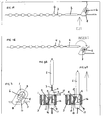
- Figure 1 is a side view of the steps involved during operation of the fastening device.
- Figure 1A shows the arrangement of the fastening device elements on the cord.
- Figure 1B shows the fastening device after the cord has been cut between the threading guide and the female fastening element.
- Figure 1C shows the threading guide being inserted into the female fastening element.
- Figure 1D shows a stop in position just beyond the resilient tongue of the female fastening element, and the configuration of the device when a force is applied to the cord.
- Figure 2 shows a top view of the steps involved during operation of the fastening device.
- Figure 2A shows the fastening device after the cord has been cut between the threading guide and the female fastening element.
- Figure 2B shows the threading guide being inserted into the female fastening element.
- Figure 2C shows the cord being pulled through the channel of the female fastening element, with a stop in position just beyond the resilient tongue.
- Figure 2D shows the configuration of the device when a force is applied to the cord.
- Figure 3 shows a cross sectional view through plane A-A of the female fastening element, as indicated in figure 2A.
- Figure 4 shows a cross sectional view of the fastening channel, taken along line B-B of figure 3.
- Figure 4A shows the threading guide in the channel.
- figure 4B a first stop has been pulled through the channel.
- Figure 5 shows a car seat cover with a hem, through which the fastening device is threaded.
- Figure 5A shows the cover before the fastening device is fastened, and
- figure 5B shows the fastening device after the fastening device has been fastened.
- the fastener comprises a female fastening element (1), a threading guide (2), a flexible cord (3) and a plurality of stops (4).
- the female fastening element (1), threading guide (2) and stops (4) are all mounted or moulded onto the cord (3).
- the stops (4) are attached at regular intervals along the cord (3).
- the fastening device is initially provided as a closed loop, and the cord (3) must be cut directly between the threading guide (2) and female fastening element (1), prior to use.
- Figure 1B shows the fastening device after it has been cut as shown in figure 1A.
- the threading guide (2) is now ready to be inserted into the channel (6) of the female fastening element (1).
- Figure 1C shows the threading guide (2) inside the channel (6).
- the diameter of the threading guide (2) is small enough to allow it to thread through the channel (6) without interaction with the resilient tongue (8).
- Figure 1D shows a stop (11) inside the channel (6), just past the resilient tongue (8).
- the fastening device has been subjected to an applied force F, the result of which is to tilt the female fastening element (1) and to engage the stop (11) against the resilient tongue (8), preventing the withdrawal of the stop-mounted end of the cord (3) from the channel (6).
- the fact that the female fastening element (1) tilts in this way results in the cord (3) doubling back on itself when a force F is applied. This doubling back improves the strength of the fastening device.
- Figure 2 shows a top view of the same process as figure 1.
- Figure 2A corresponds to figure 1B, and shows the fastening device when the threading guide (2) is ready to be inserted into the channel (6).
- Figure 2B corresponds to figure 1C, and shows the threading guide (2) inside the channel (6).
- the channel (6) runs through the female fastening element (1) in a direction perpendicular to that in which the cord (3) runs through the female fastening element (1).
- Figure 2C shows a first stop (11) inserted almost completely through the channel (6), and a second stop beginning to enter the channel (6).
- the first stop (11) is sufficiently far through the channel (6) that it has passed the resilient tongue (8).
- Figure 2D corresponds to figure 1D, showing the first stop (11) and second stop in the same position relative to the channel (6) as was shown in figure 2C, and with a force F applied to the cord (3).
- the region of the stop-mounted end of the cord (3) just before it enters the channel (6) is approximately co-linear with the region of the opposite end of the cord (3) which exits from the female fastening element (1).
- FIG. 3 shows a more detailed view of the female fastening element (1).
- the female fastening element (1) is mounted onto the cord (3), and the direction in which the cord (3) runs inside the female fastening element (1) is perpendicular to the direction of the channel (6).
- a tongue (8) projects into the channel (6), and on the wall of the channel (6) directly behind the tongue (8), a hollow recessed cavity (10) provides a space into which the tongue (8) can be displaced.
- Figure 4 shows the operation of the device in more detail.
- Figure 4A shows the threading guide (2) inside the channel (6), and almost completely past the tongue (8).
- Figure 4B shows a first stop (11) pushed through the channel (6) and past the tongue (8), and a second stop which has not yet reached the tongue (8).
- One end (18) of the tongue (8) is attached to the wall of the channel (6) at the entry end (14) of the channel (6).
- the other end (19) of the tongue (8) has a flat surface, and projects into the channel (6) towards the exit end (15) of the channel (6).
- the cavity (10) is located in the wall of the channel (6), directly behind the tongue (8).
- the stops (4) are bullet shaped, having a rounded front surface (16) and a flattened rear surface (17). This makes it easy for the front of a stop to displace the tongue (8) into the cavity (10) as it enters the channel (6) from the entry end (14).
- the flat rear surface (17) of the stop engages with the flat end surface (19) of the tongue (8), providing a barrier which prevents any further movement of the stop in a direction back into the channel (6).
- Figure 5 shows a car seat cover, in which a hem (20) is peripheral to an opening (23) of the cover.
- the hem (20) fits below the car seat, and the remaining part (21) of the cover fits on top of the car seat.
- a fastening device (24) according to the present invention is shown threaded through the hem (20).
- the cover is slid onto the seat by means of the opening (23), and the fastening device (24) is then closed and tightened to tension the cover on the seat.
- this fastening device (24) is unfastened, but in figure 5B, the fastening device (24) has been fastened, forming a loop, although it has not yet been fully tightened.
Landscapes
- Engineering & Computer Science (AREA)
- Aviation & Aerospace Engineering (AREA)
- Transportation (AREA)
- Mechanical Engineering (AREA)
- Seats For Vehicles (AREA)
- Non-Silver Salt Photosensitive Materials And Non-Silver Salt Photography (AREA)
- Liquid Crystal (AREA)
- Rear-View Mirror Devices That Are Mounted On The Exterior Of The Vehicle (AREA)
- Chair Legs, Seat Parts, And Backrests (AREA)
Priority Applications (5)
| Application Number | Priority Date | Filing Date | Title |
|---|---|---|---|
| PT00311250T PT1215079E (pt) | 2000-12-15 | 2000-12-15 | Fecho para capas de assento de carro |
| AT00311250T ATE269238T1 (de) | 2000-12-15 | 2000-12-15 | Befestigung von kraftfahrzeugsitzbezügen |
| DE60011641T DE60011641T2 (de) | 2000-12-15 | 2000-12-15 | Befestigung von Kraftfahrzeugsitzbezügen |
| EP00311250A EP1215079B1 (fr) | 2000-12-15 | 2000-12-15 | Fixation de housses pour sièges de véhicule |
| ES00311250T ES2221831T3 (es) | 2000-12-15 | 2000-12-15 | Fijacion para fundas de asiento de automovil. |
Applications Claiming Priority (1)
| Application Number | Priority Date | Filing Date | Title |
|---|---|---|---|
| EP00311250A EP1215079B1 (fr) | 2000-12-15 | 2000-12-15 | Fixation de housses pour sièges de véhicule |
Publications (2)
| Publication Number | Publication Date |
|---|---|
| EP1215079A1 true EP1215079A1 (fr) | 2002-06-19 |
| EP1215079B1 EP1215079B1 (fr) | 2004-06-16 |
Family
ID=8173450
Family Applications (1)
| Application Number | Title | Priority Date | Filing Date |
|---|---|---|---|
| EP00311250A Expired - Lifetime EP1215079B1 (fr) | 2000-12-15 | 2000-12-15 | Fixation de housses pour sièges de véhicule |
Country Status (5)
| Country | Link |
|---|---|
| EP (1) | EP1215079B1 (fr) |
| AT (1) | ATE269238T1 (fr) |
| DE (1) | DE60011641T2 (fr) |
| ES (1) | ES2221831T3 (fr) |
| PT (1) | PT1215079E (fr) |
Cited By (2)
| Publication number | Priority date | Publication date | Assignee | Title |
|---|---|---|---|---|
| FR2964349A1 (fr) * | 2010-09-07 | 2012-03-09 | Ykk France | Fixation d'une housse a un cadre |
| EP3066944A1 (fr) * | 2015-03-09 | 2016-09-14 | Ingo Schröder | Agencement d'un element en forme de bande sur un systeme de serrage de cordon, produit textile comprenant un tel agencement et procede de fabrication d'un element en forme de bande |
Citations (3)
| Publication number | Priority date | Publication date | Assignee | Title |
|---|---|---|---|---|
| US3967345A (en) * | 1975-02-07 | 1976-07-06 | Tokyo Style Company, Ltd. | Binding strap |
| US5150947A (en) * | 1991-09-20 | 1992-09-29 | Saddleman, Inc. | Dual-tongue seat cover attachment |
| US5459907A (en) | 1992-11-04 | 1995-10-24 | Itw De France | Annular fastening device |
-
2000
- 2000-12-15 AT AT00311250T patent/ATE269238T1/de not_active IP Right Cessation
- 2000-12-15 EP EP00311250A patent/EP1215079B1/fr not_active Expired - Lifetime
- 2000-12-15 PT PT00311250T patent/PT1215079E/pt unknown
- 2000-12-15 ES ES00311250T patent/ES2221831T3/es not_active Expired - Lifetime
- 2000-12-15 DE DE60011641T patent/DE60011641T2/de not_active Expired - Lifetime
Patent Citations (3)
| Publication number | Priority date | Publication date | Assignee | Title |
|---|---|---|---|---|
| US3967345A (en) * | 1975-02-07 | 1976-07-06 | Tokyo Style Company, Ltd. | Binding strap |
| US5150947A (en) * | 1991-09-20 | 1992-09-29 | Saddleman, Inc. | Dual-tongue seat cover attachment |
| US5459907A (en) | 1992-11-04 | 1995-10-24 | Itw De France | Annular fastening device |
Cited By (2)
| Publication number | Priority date | Publication date | Assignee | Title |
|---|---|---|---|---|
| FR2964349A1 (fr) * | 2010-09-07 | 2012-03-09 | Ykk France | Fixation d'une housse a un cadre |
| EP3066944A1 (fr) * | 2015-03-09 | 2016-09-14 | Ingo Schröder | Agencement d'un element en forme de bande sur un systeme de serrage de cordon, produit textile comprenant un tel agencement et procede de fabrication d'un element en forme de bande |
Also Published As
| Publication number | Publication date |
|---|---|
| ATE269238T1 (de) | 2004-07-15 |
| DE60011641T2 (de) | 2005-06-30 |
| PT1215079E (pt) | 2004-08-31 |
| ES2221831T3 (es) | 2005-01-16 |
| EP1215079B1 (fr) | 2004-06-16 |
| DE60011641D1 (de) | 2004-07-22 |
Similar Documents
| Publication | Publication Date | Title |
|---|---|---|
| US5379496A (en) | Cord release buckle | |
| US4800629A (en) | Plastic buckle | |
| CN1149031C (zh) | 带端固定器 | |
| US5758390A (en) | Reversible cable tie | |
| EP0665807B1 (fr) | Serre-cable s'enfilant facilement | |
| US20030042350A1 (en) | Extendible and retractable lead | |
| US4862560A (en) | Irreversible tie strap with specialized clasp to permit the strap to be inserted through the clasp twice | |
| US5459907A (en) | Annular fastening device | |
| US5566427A (en) | Strap clip and retainer | |
| GB2308153A (en) | Flexible tie for cables | |
| AU2004244195A1 (en) | Cable tie | |
| US20050166369A1 (en) | Buckle | |
| US20020062543A1 (en) | Aid for threading a seat belt through a child safety restraint | |
| US6401310B1 (en) | Snowshoe buckle | |
| US6473942B1 (en) | Cable tie with thread force reducing structure | |
| DE4239812A1 (fr) | ||
| US10704646B2 (en) | Bungee cord lock and method of use | |
| US5622136A (en) | Boat canopy mounting system | |
| EP0522033B1 (fr) | Element de fixation servant a fixer un ecran de protection a un echafaudage ou a toute autre structure de support similaire, et outil utilise pour le montage de cet element de fixation | |
| EP1215079B1 (fr) | Fixation de housses pour sièges de véhicule | |
| US4358081A (en) | Bundling fastener for bars and wires | |
| US5005910A (en) | Apparatus for restricting relative movement of belt portions | |
| EP1136331B1 (fr) | Ensemble languette de verrouillage pour une ceinture de sécurité de véhicule | |
| US7036849B2 (en) | Stop device | |
| GB2097053A (en) | Plastics tie |
Legal Events
| Date | Code | Title | Description |
|---|---|---|---|
| PUAI | Public reference made under article 153(3) epc to a published international application that has entered the european phase |
Free format text: ORIGINAL CODE: 0009012 |
|
| AK | Designated contracting states |
Kind code of ref document: A1 Designated state(s): AT BE CH CY DE DK ES FI FR GB GR IE IT LI LU MC NL PT SE TR |
|
| AX | Request for extension of the european patent |
Free format text: AL;LT;LV;MK;RO;SI |
|
| 17P | Request for examination filed |
Effective date: 20021219 |
|
| AKX | Designation fees paid |
Designated state(s): AT BE CH CY DE DK ES FI FR GB GR IE IT LI LU MC NL PT SE TR |
|
| GRAP | Despatch of communication of intention to grant a patent |
Free format text: ORIGINAL CODE: EPIDOSNIGR1 |
|
| GRAS | Grant fee paid |
Free format text: ORIGINAL CODE: EPIDOSNIGR3 |
|
| GRAA | (expected) grant |
Free format text: ORIGINAL CODE: 0009210 |
|
| AK | Designated contracting states |
Kind code of ref document: B1 Designated state(s): AT BE CH CY DE DK ES FI FR GB GR IE IT LI LU MC NL PT SE TR |
|
| PG25 | Lapsed in a contracting state [announced via postgrant information from national office to epo] |
Ref country code: LI Free format text: LAPSE BECAUSE OF FAILURE TO SUBMIT A TRANSLATION OF THE DESCRIPTION OR TO PAY THE FEE WITHIN THE PRESCRIBED TIME-LIMIT Effective date: 20040616 Ref country code: CH Free format text: LAPSE BECAUSE OF FAILURE TO SUBMIT A TRANSLATION OF THE DESCRIPTION OR TO PAY THE FEE WITHIN THE PRESCRIBED TIME-LIMIT Effective date: 20040616 Ref country code: TR Free format text: LAPSE BECAUSE OF FAILURE TO SUBMIT A TRANSLATION OF THE DESCRIPTION OR TO PAY THE FEE WITHIN THE PRESCRIBED TIME-LIMIT Effective date: 20040616 Ref country code: CY Free format text: LAPSE BECAUSE OF FAILURE TO SUBMIT A TRANSLATION OF THE DESCRIPTION OR TO PAY THE FEE WITHIN THE PRESCRIBED TIME-LIMIT Effective date: 20040616 Ref country code: NL Free format text: LAPSE BECAUSE OF FAILURE TO SUBMIT A TRANSLATION OF THE DESCRIPTION OR TO PAY THE FEE WITHIN THE PRESCRIBED TIME-LIMIT Effective date: 20040616 Ref country code: AT Free format text: LAPSE BECAUSE OF FAILURE TO SUBMIT A TRANSLATION OF THE DESCRIPTION OR TO PAY THE FEE WITHIN THE PRESCRIBED TIME-LIMIT Effective date: 20040616 Ref country code: FI Free format text: LAPSE BECAUSE OF FAILURE TO SUBMIT A TRANSLATION OF THE DESCRIPTION OR TO PAY THE FEE WITHIN THE PRESCRIBED TIME-LIMIT Effective date: 20040616 |
|
| REG | Reference to a national code |
Ref country code: GB Ref legal event code: FG4D |
|
| REG | Reference to a national code |
Ref country code: CH Ref legal event code: EP |
|
| REF | Corresponds to: |
Ref document number: 60011641 Country of ref document: DE Date of ref document: 20040722 Kind code of ref document: P |
|
| REG | Reference to a national code |
Ref country code: IE Ref legal event code: FG4D |
|
| REG | Reference to a national code |
Ref country code: PT Ref legal event code: SC4A Free format text: AVAILABILITY OF NATIONAL TRANSLATION Effective date: 20040630 |
|
| PG25 | Lapsed in a contracting state [announced via postgrant information from national office to epo] |
Ref country code: DK Free format text: LAPSE BECAUSE OF FAILURE TO SUBMIT A TRANSLATION OF THE DESCRIPTION OR TO PAY THE FEE WITHIN THE PRESCRIBED TIME-LIMIT Effective date: 20040916 Ref country code: SE Free format text: LAPSE BECAUSE OF FAILURE TO SUBMIT A TRANSLATION OF THE DESCRIPTION OR TO PAY THE FEE WITHIN THE PRESCRIBED TIME-LIMIT Effective date: 20040916 Ref country code: GR Free format text: LAPSE BECAUSE OF FAILURE TO SUBMIT A TRANSLATION OF THE DESCRIPTION OR TO PAY THE FEE WITHIN THE PRESCRIBED TIME-LIMIT Effective date: 20040916 |
|
| NLV1 | Nl: lapsed or annulled due to failure to fulfill the requirements of art. 29p and 29m of the patents act | ||
| PG25 | Lapsed in a contracting state [announced via postgrant information from national office to epo] |
Ref country code: LU Free format text: LAPSE BECAUSE OF NON-PAYMENT OF DUE FEES Effective date: 20041215 Ref country code: IE Free format text: LAPSE BECAUSE OF NON-PAYMENT OF DUE FEES Effective date: 20041215 |
|
| ET | Fr: translation filed | ||
| PG25 | Lapsed in a contracting state [announced via postgrant information from national office to epo] |
Ref country code: MC Free format text: LAPSE BECAUSE OF NON-PAYMENT OF DUE FEES Effective date: 20041231 |
|
| REG | Reference to a national code |
Ref country code: CH Ref legal event code: PL |
|
| REG | Reference to a national code |
Ref country code: ES Ref legal event code: FG2A Ref document number: 2221831 Country of ref document: ES Kind code of ref document: T3 |
|
| PLBE | No opposition filed within time limit |
Free format text: ORIGINAL CODE: 0009261 |
|
| STAA | Information on the status of an ep patent application or granted ep patent |
Free format text: STATUS: NO OPPOSITION FILED WITHIN TIME LIMIT |
|
| 26N | No opposition filed |
Effective date: 20050317 |
|
| REG | Reference to a national code |
Ref country code: IE Ref legal event code: MM4A |
|
| PGFP | Annual fee paid to national office [announced via postgrant information from national office to epo] |
Ref country code: PT Payment date: 20081204 Year of fee payment: 9 |
|
| PGFP | Annual fee paid to national office [announced via postgrant information from national office to epo] |
Ref country code: IT Payment date: 20081224 Year of fee payment: 9 |
|
| PGFP | Annual fee paid to national office [announced via postgrant information from national office to epo] |
Ref country code: ES Payment date: 20090120 Year of fee payment: 9 |
|
| PGFP | Annual fee paid to national office [announced via postgrant information from national office to epo] |
Ref country code: GB Payment date: 20081210 Year of fee payment: 9 |
|
| PGFP | Annual fee paid to national office [announced via postgrant information from national office to epo] |
Ref country code: BE Payment date: 20090112 Year of fee payment: 9 |
|
| REG | Reference to a national code |
Ref country code: PT Ref legal event code: MM4A Free format text: LAPSE DUE TO NON-PAYMENT OF FEES Effective date: 20100615 |
|
| BERE | Be: lapsed |
Owner name: *YKK FRANCE S.A.R.L. Effective date: 20091231 |
|
| PG25 | Lapsed in a contracting state [announced via postgrant information from national office to epo] |
Ref country code: PT Free format text: LAPSE BECAUSE OF NON-PAYMENT OF DUE FEES Effective date: 20100615 |
|
| GBPC | Gb: european patent ceased through non-payment of renewal fee |
Effective date: 20091215 |
|
| PG25 | Lapsed in a contracting state [announced via postgrant information from national office to epo] |
Ref country code: BE Free format text: LAPSE BECAUSE OF NON-PAYMENT OF DUE FEES Effective date: 20091231 |
|
| PG25 | Lapsed in a contracting state [announced via postgrant information from national office to epo] |
Ref country code: GB Free format text: LAPSE BECAUSE OF NON-PAYMENT OF DUE FEES Effective date: 20091215 |
|
| PG25 | Lapsed in a contracting state [announced via postgrant information from national office to epo] |
Ref country code: IT Free format text: LAPSE BECAUSE OF NON-PAYMENT OF DUE FEES Effective date: 20091215 |
|
| REG | Reference to a national code |
Ref country code: ES Ref legal event code: FD2A Effective date: 20110401 |
|
| PG25 | Lapsed in a contracting state [announced via postgrant information from national office to epo] |
Ref country code: ES Free format text: LAPSE BECAUSE OF NON-PAYMENT OF DUE FEES Effective date: 20110322 |
|
| PG25 | Lapsed in a contracting state [announced via postgrant information from national office to epo] |
Ref country code: ES Free format text: LAPSE BECAUSE OF NON-PAYMENT OF DUE FEES Effective date: 20091216 |
|
| PGFP | Annual fee paid to national office [announced via postgrant information from national office to epo] |
Ref country code: DE Payment date: 20131211 Year of fee payment: 14 |
|
| PGFP | Annual fee paid to national office [announced via postgrant information from national office to epo] |
Ref country code: FR Payment date: 20131209 Year of fee payment: 14 |
|
| REG | Reference to a national code |
Ref country code: DE Ref legal event code: R119 Ref document number: 60011641 Country of ref document: DE |
|
| REG | Reference to a national code |
Ref country code: FR Ref legal event code: ST Effective date: 20150831 |
|
| PG25 | Lapsed in a contracting state [announced via postgrant information from national office to epo] |
Ref country code: DE Free format text: LAPSE BECAUSE OF NON-PAYMENT OF DUE FEES Effective date: 20150701 |
|
| PG25 | Lapsed in a contracting state [announced via postgrant information from national office to epo] |
Ref country code: FR Free format text: LAPSE BECAUSE OF NON-PAYMENT OF DUE FEES Effective date: 20141231 |