EP1215151A2 - Système de traitement de fils - Google Patents
Système de traitement de fils Download PDFInfo
- Publication number
- EP1215151A2 EP1215151A2 EP01126223A EP01126223A EP1215151A2 EP 1215151 A2 EP1215151 A2 EP 1215151A2 EP 01126223 A EP01126223 A EP 01126223A EP 01126223 A EP01126223 A EP 01126223A EP 1215151 A2 EP1215151 A2 EP 1215151A2
- Authority
- EP
- European Patent Office
- Prior art keywords
- thread
- bobbin
- processing system
- mandrel
- spool
- Prior art date
- Legal status (The legal status is an assumption and is not a legal conclusion. Google has not performed a legal analysis and makes no representation as to the accuracy of the status listed.)
- Withdrawn
Links
Images
Classifications
-
- D—TEXTILES; PAPER
- D04—BRAIDING; LACE-MAKING; KNITTING; TRIMMINGS; NON-WOVEN FABRICS
- D04B—KNITTING
- D04B15/00—Details of, or auxiliary devices incorporated in, weft knitting machines, restricted to machines of this kind
- D04B15/38—Devices for supplying, feeding, or guiding threads to needles
- D04B15/48—Thread-feeding devices
- D04B15/482—Thread-feeding devices comprising a rotatable or stationary intermediate storage drum from which the thread is axially and intermittently pulled off; Devices which can be switched between positive feed and intermittent feed
-
- D—TEXTILES; PAPER
- D03—WEAVING
- D03D—WOVEN FABRICS; METHODS OF WEAVING; LOOMS
- D03D47/00—Looms in which bulk supply of weft does not pass through shed, e.g. shuttleless looms, gripper shuttle looms, dummy shuttle looms
- D03D47/34—Handling the weft between bulk storage and weft-inserting means
-
- D—TEXTILES; PAPER
- D04—BRAIDING; LACE-MAKING; KNITTING; TRIMMINGS; NON-WOVEN FABRICS
- D04B—KNITTING
- D04B15/00—Details of, or auxiliary devices incorporated in, weft knitting machines, restricted to machines of this kind
- D04B15/38—Devices for supplying, feeding, or guiding threads to needles
- D04B15/40—Holders or supports for thread packages
Definitions
- the invention relates to a thread processing system according to the preamble of the claim 1.
- Thread delivery device at least one supply spool held on a spool so assigned that the supply spool with its unwinding end at some distance from the rear of the thread feeder housing and from the supply spool pulled thread from backwards into the mouth of the feed channel in the thread delivery device enters.
- Each coil mandrel is held stationary, for example in one so-called coil frame. This requires considerable construction work and a lot Space behind the thread delivery devices and a long one, which is the cause of faults Thread travel from the supply spool into the thread delivery device.
- the invention has for its object to a system of the type mentioned create, while maintaining the advantage of the central thread feed by the Feed channel of the delivery device the structural effort for holding the supply reel reduced and the thread travel to the stationary storage body is optimally short are.
- the housing of the thread delivery device acts as a carrier for the bobbin mandrel and Coil holder. This significantly reduces the construction effort and enables it, the thread travel from the supply spool into the thread feed channel optimally to keep short. Anyhow existing on the back of the housing of the delivery device Space is used optimally.
- Several thread delivery devices equipped with their supply bobbins can be grouped close together in the system.
- Assembly and replacement of the supply spool are user-friendly, if on the Housing attached coil mandrel at least one fastener for the coil core is arranged, the spool being mounted so that its unwinding end of the back of the housing of the thread delivery device points away.
- the distance of the supply spool from the back of the thread delivery device can be also keep it short because the coil holder has a U-shaped bracket is who fix the spool between his U-legs with a holding block leaves.
- a is used to fix the coil core on the coil dome known gear-shaped holder with elastically deformable clamping wings used.
- the full supply spool is only attached to the holder and clamped. An empty coil core can be easily pulled off. By longitudinally adjusting the holder different supply reel sizes can be securely attached.
- a brake hub is arranged on the spool, on which by means of a thread brake element, e.g. a straw ring that controls the thread run and the thread tension be kept constant.
- a thread brake element e.g. a straw ring that controls the thread run and the thread tension be kept constant.
- Handling is user-friendly if there is a holding bush on the mandrel is longitudinally adjustable for the brake hub and the cover plate.
- the holding bush should be a Have wing with a stop for the cover plate.
- Front locking elements which interact with counter-locking elements of the brake hub to quickly remove the brake hub and cover plate when changing the supply spool and put it back behind the new, full supply spool.
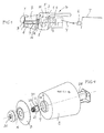
- a thread processing system S in FIG. 1 comprises a thread-consuming one as main components Textile machine T, e.g. a loom, a thread in that Tray of the weaving machine intermittently input device E, upstream the entry device E a thread delivery device F, and directly on the thread delivery device F one Supply spool B for a thread Y, which goes from the supply spool B into the thread delivery device F retracted, cached therein and intermittent by the entry device is entered in the textile machine T.
- Textile machine T e.g. a loom
- the thread delivery device F has a stationary housing 1, in which one Winding shaft 2 with a winding element 3 can be driven in rotation by a drive motor M. is. Furthermore, a storage body 4 is arranged stationary in the housing.
- the Winding shaft 2 and the winding element 3 are hollow and form together an internal feed channel for the thread Y, the feed channel being its Mouth 8 has at the rear R of the housing 1.
- a coil holder H attached directly to the rear R or to the housing 1, the one an extension of the winding shaft 2 forming hollow mandrel 7 defines.
- the coil mandrel 7 has at its free end pointing away from the rear R. a feed opening 9 for the thread Y.
- the supply spool B is from the rear R technological unwinding end held on the coil dome 7 by means of its coil core 6.
- a cover disk on the reel mandrel 7 D arranged, the outer diameter of which is approximately the outer diameter of the unwinding end of the supply reel B corresponds.
- Thread runs around the cover disk D and passes through the feed opening 9 in the mandrel 7. After he has passed through the coil dome 7, he runs through the mouth 8 and the feed channel of the rotating winding element up to the peripheral surface of the storage body 4.
- the textile machine T could also be a knitting machine or another thread processing machine his.
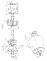
- FIG. 1 The embodiment of FIG. 1 is explained in detail with reference to FIGS. 2 to 4.
- the coil holding device H has a U-shaped bracket with two in FIG. 2 spaced U-legs 24, which are penetrated by the coil mandrel 7.
- a longitudinally pierced holding block 25 is positioned between the U-legs 24, which has a clamping screw 26 for fixing the mandrel 7. Possibly passes through the mouth 8 of the feed channel of the yarn feeder the one U-leg 24.
- the bracket is with this U-leg 24, for example, at 13 directly the rear side R of the thread delivery device, specifically at the mouth 8.
- the attachment points 13 could, however, also be further out than shown.
- each holder A has a hub part 15 which with a Set screw 16 is adjustable and fixable in the longitudinal direction on the coil dome.
- the hub part 15 carries a gear-shaped holding body 17 with elastically deformable Material existing wings 18, e.g. made of plastic or rubber, if necessary.
- two supply spools B can even be attached to one another.
- the cover plate D In front of the smaller holder A, the cover plate D is positioned, which is a conical or has convexly rounded thread guide surface 19.
- the cover plate D In front of the cover plate D can Brake hub M to be positioned on the mandrel 7, which has a seat 20 with a Retaining bead 21 for a thread braking element P indicated by dashed lines, e.g. one Straw ring, owns.
- the exposed nose area 22 of the brake hub N can be conical be designed.
- a thread eyelet 23 In the feed opening 9 of the hollow mandrel 7 is expedient a thread eyelet 23 is arranged.
- D and N For setting components A, D and N they can be adjusted to the size of the supply spool along the spool mandrel 7 adjust and fix.
- the full supply spool B is arranged on the spool 7 and with the Holding device H mounted on the back of the thread delivery device.
- the cover plate D is placed at the unwinding end of the supply reel B.
- Size of the supply spool B protrudes the free end of the spool over the brake hub N.
- a retaining bushing K is fastened on the spool mandrel 7.
- the axial position the retaining bushing K can be selected with a set screw.
- the holding bush has an airfoil 27 with an end flange 28 for positioning the cover plate D.
- locking elements 29 are provided at the free end of the holding bushing K, which interact positively with counter-elements 30 in the brake hub N. can.
- the cover plate D is up to the system Flange 28 or, if desired, up to the free end of the coil core 6, threaded.
- the brake hub N is then threaded on and with its counter-locking elements 30 locked with the locking elements 29.
- the removable components are removed in reverse order.
- the cantilever length of the coil mandrel 7 is optionally made use of the length of the holding block 25 is set such that the thread running out of the supply reel B an optimally short path to the mouth 8 of the thread feed channel in the thread delivery device Has.
- the overhang length of the coil mandrel 7 could be such that that the feed opening 9 lies in the brake hub N.
Landscapes
- Engineering & Computer Science (AREA)
- Textile Engineering (AREA)
- Storage Of Web-Like Or Filamentary Materials (AREA)
- Forwarding And Storing Of Filamentary Material (AREA)
Applications Claiming Priority (2)
| Application Number | Priority Date | Filing Date | Title |
|---|---|---|---|
| DE2000154688 DE10054688A1 (de) | 2000-11-03 | 2000-11-03 | Fadenverarbeitendes System |
| DE10054688 | 2000-11-03 |
Publications (2)
| Publication Number | Publication Date |
|---|---|
| EP1215151A2 true EP1215151A2 (fr) | 2002-06-19 |
| EP1215151A3 EP1215151A3 (fr) | 2003-09-17 |
Family
ID=7662133
Family Applications (1)
| Application Number | Title | Priority Date | Filing Date |
|---|---|---|---|
| EP01126223A Withdrawn EP1215151A3 (fr) | 2000-11-03 | 2001-11-05 | Système de traitement de fils |
Country Status (2)
| Country | Link |
|---|---|
| EP (1) | EP1215151A3 (fr) |
| DE (1) | DE10054688A1 (fr) |
Cited By (2)
| Publication number | Priority date | Publication date | Assignee | Title |
|---|---|---|---|---|
| CN101927918A (zh) * | 2010-07-21 | 2010-12-29 | 张家港市攀峰科技有限公司 | 用于将筒子芯安装在支轴上的上支承装置 |
| CN102140724A (zh) * | 2011-04-19 | 2011-08-03 | 许晓华 | 一种转轴结构改进 |
Families Citing this family (2)
| Publication number | Priority date | Publication date | Assignee | Title |
|---|---|---|---|---|
| CN102719975A (zh) * | 2012-07-06 | 2012-10-10 | 常熟市方园纺织器材厂 | 防静电织机纬纱筒管 |
| WO2022249122A1 (fr) * | 2021-05-27 | 2022-12-01 | Prashant Khandu Narawade | Ensemble porte-bobines de filature à anneaux |
Family Cites Families (5)
| Publication number | Priority date | Publication date | Assignee | Title |
|---|---|---|---|---|
| DE813673C (de) * | 1950-04-14 | 1951-09-17 | Wilhelm Klein | Einrichtung zum UEberkopfabziehen von Spulen |
| GB1262179A (en) * | 1968-10-14 | 1972-02-02 | Rosen Karl I J | Thread storage and delivery device for textile machines |
| US3702176A (en) * | 1971-01-13 | 1972-11-07 | Rosen Karl I J | Yarn storing device |
| US4226379A (en) * | 1979-12-06 | 1980-10-07 | Leesona Corporation | Loom storage feeder improvement |
| DE19612720A1 (de) * | 1996-03-29 | 1997-10-02 | Iro Ab | Fadenliefergerät |
-
2000
- 2000-11-03 DE DE2000154688 patent/DE10054688A1/de not_active Withdrawn
-
2001
- 2001-11-05 EP EP01126223A patent/EP1215151A3/fr not_active Withdrawn
Cited By (2)
| Publication number | Priority date | Publication date | Assignee | Title |
|---|---|---|---|---|
| CN101927918A (zh) * | 2010-07-21 | 2010-12-29 | 张家港市攀峰科技有限公司 | 用于将筒子芯安装在支轴上的上支承装置 |
| CN102140724A (zh) * | 2011-04-19 | 2011-08-03 | 许晓华 | 一种转轴结构改进 |
Also Published As
| Publication number | Publication date |
|---|---|
| EP1215151A3 (fr) | 2003-09-17 |
| DE10054688A1 (de) | 2002-05-16 |
Similar Documents
| Publication | Publication Date | Title |
|---|---|---|
| DE102017109819B4 (de) | Umwickeln eines Leitungssatzes mit Band | |
| DE10139072B4 (de) | Serviceaggregat zum Wiederanspinnen von Arbeitsstellen einer Offenend-Spinnmaschine | |
| EP0234208B1 (fr) | Appareil pour emmagasiner et délivrer du fil, en particulier pour machines textiles | |
| DE2543986A1 (de) | Verfahren und vorrichtung zur sicherung einer reservewicklung auf einer spulenhuelse | |
| DE2426680B2 (de) | Fadenliefer- und speichervorrichtung fuer strickmaschinen | |
| DE112018005488T5 (de) | Filamentwickelvorrichtung und garneinfädelverfahren in der filamentwickelvorrichtung | |
| DE4336994C1 (de) | Fadenliefervorrichtung mit stufenlos einstellbarer Fadenabzugspannung | |
| EP1215151A2 (fr) | Système de traitement de fils | |
| DE2051311B2 (de) | Vorrichtung zur automatischen Verlegung einer Fadenreserve auf eine Spulenhülse außerhalb des Spulbereiches | |
| EP0521816B1 (fr) | Procédé pour transferer le fil d'une bobine pleine à une bobine vide et un bobinoir | |
| DE10239334B4 (de) | Fadenspulmaschine mit einem Spannungsdetektor | |
| WO1984004550A1 (fr) | Procede et dispositif pour la filature de fibres | |
| DE3106947A1 (de) | "spulvorrichtung zum aufspulen von flachfaeden zu zylindrischen kreuzspulen" | |
| DE2716017C2 (de) | Fadenbremse an einem Fadenspeicher | |
| DE2911864C2 (de) | Vorrichtung zur Messung von fadenförmigem Material, z.B. bei einer Webmaschine | |
| CH436065A (de) | Spindel zur Aufnahme von Garnen, Fäden, Drähten oder dergleichen, insbesondere jedoch von Abfallgarn | |
| DE3515104C1 (de) | Vorrichtung zur zwangsweisen Zulieferung von Elastomerfaeden an Textilmaschinen | |
| DE1602265A1 (de) | Drahtablaufbremse | |
| DE2036040A1 (de) | Vorrichtung zum Aufbringen einer Draht wendel auf ein dünnes Drahtseil | |
| EP3165639B1 (fr) | Frein de fil extérieur, machine de câblage et de cordage comprenant un frein de fil extérieur et procédé de fonctionnement d'une telle machine de câblage ou de torsadage | |
| DE102024101350B3 (de) | Werkstückführung sowie Vorrichtung zum Zuführen eines langgestreckten Werkstücks zu einer Umformmaschine | |
| DE8221343U1 (de) | Drahtspann- und auffangapparat | |
| DE2613427C2 (de) | Vorrichtung zum Bremsen des Fadens an Textilmaschinen | |
| DE60203338T2 (de) | Schnell-Befestigungsvorrichtung für Bremseinheiten von Schussfadenliefervorrichtungen für Webmaschinen | |
| DE2737048A1 (de) | Fadenspulmaschine zum automatischen verankern, verdrillen und aufwickeln eines fadens oder eines aehnlichen gegenstandes auf eine spule |
Legal Events
| Date | Code | Title | Description |
|---|---|---|---|
| PUAI | Public reference made under article 153(3) epc to a published international application that has entered the european phase |
Free format text: ORIGINAL CODE: 0009012 |
|
| AK | Designated contracting states |
Kind code of ref document: A2 Designated state(s): AT BE CH CY DE DK ES FI FR GB GR IE IT LI LU MC NL PT SE TR |
|
| AX | Request for extension of the european patent |
Free format text: AL;LT;LV;MK;RO;SI |
|
| PUAL | Search report despatched |
Free format text: ORIGINAL CODE: 0009013 |
|
| AK | Designated contracting states |
Kind code of ref document: A3 Designated state(s): AT BE CH CY DE DK ES FI FR GB GR IE IT LI LU MC NL PT SE TR |
|
| AX | Request for extension of the european patent |
Extension state: AL LT LV MK RO SI |
|
| RIC1 | Information provided on ipc code assigned before grant |
Ipc: 7D 04B 15/48 B Ipc: 7D 03D 47/34 B Ipc: 7B 65H 51/22 A |
|
| AKX | Designation fees paid | ||
| REG | Reference to a national code |
Ref country code: DE Ref legal event code: 8566 |
|
| STAA | Information on the status of an ep patent application or granted ep patent |
Free format text: STATUS: THE APPLICATION IS DEEMED TO BE WITHDRAWN |
|
| 18D | Application deemed to be withdrawn |
Effective date: 20040318 |