EP1215338A2 - Schürfleiste für eine Schneeräumvorrichtung - Google Patents
Schürfleiste für eine Schneeräumvorrichtung Download PDFInfo
- Publication number
- EP1215338A2 EP1215338A2 EP01129539A EP01129539A EP1215338A2 EP 1215338 A2 EP1215338 A2 EP 1215338A2 EP 01129539 A EP01129539 A EP 01129539A EP 01129539 A EP01129539 A EP 01129539A EP 1215338 A2 EP1215338 A2 EP 1215338A2
- Authority
- EP
- European Patent Office
- Prior art keywords
- scraper
- snow
- blade
- snow removing
- blades
- Prior art date
- Legal status (The legal status is an assumption and is not a legal conclusion. Google has not performed a legal analysis and makes no representation as to the accuracy of the status listed.)
- Granted
Links
Images



Classifications
-
- E—FIXED CONSTRUCTIONS
- E01—CONSTRUCTION OF ROADS, RAILWAYS, OR BRIDGES
- E01H—STREET CLEANING; CLEANING OF PERMANENT WAYS; CLEANING BEACHES; DISPERSING OR PREVENTING FOG IN GENERAL CLEANING STREET OR RAILWAY FURNITURE OR TUNNEL WALLS
- E01H5/00—Removing snow or ice from roads or like surfaces; Grading or roughening snow or ice
- E01H5/04—Apparatus propelled by animal or engine power; Apparatus propelled by hand with driven dislodging or conveying levelling elements, conveying pneumatically for the dislodged material
- E01H5/06—Apparatus propelled by animal or engine power; Apparatus propelled by hand with driven dislodging or conveying levelling elements, conveying pneumatically for the dislodged material dislodging essentially by non-driven elements, e.g. scraper blades, snow-plough blades, scoop blades
- E01H5/061—Apparatus propelled by animal or engine power; Apparatus propelled by hand with driven dislodging or conveying levelling elements, conveying pneumatically for the dislodged material dislodging essentially by non-driven elements, e.g. scraper blades, snow-plough blades, scoop blades by scraper blades
Definitions
- This invention relates to a scraper for snow removal machines for scraping snow lying on road surfaces.
- a scraper for a snow removal machine of this kind is disclosed, for example, in Japanese Utility Model Laid-Open Publication No. SHO-51-34105 entitled “Snow Removing case for Snow Removal Machine”, and in Japanese Utility Model Laid-Open Publication No. SHO-52-14347 entitled “Bottom Scraping Blade for Snow Removal Machine”.
- SHO-51-34105 includes an auxiliary ground plate fastened with bolts to a lower end portion of the snow removing case.
- the ground plate is adjustable up and down as desired. When lowered, the plate prevents an auger from contacting the ground. When raised, the plate allows the auger to crush frozen snow, thus avoiding any large resistance which would otherwise be applied to the lower end portion of the snow removing case.
- SHO-52-14347 includes a bottom scraping blade movably fitted in an arc-shaped long groove formed in a lower portion of an auger case.
- the scraping blade can be shifted upward and downward along the groove.
- the bottom scraping blade is held higher than the bottom of the auger so that the auger alone scrapes snow under reduced propulsion resistance, resulting in an efficient snow removal operation.
- Augers can scrape frozen snow or trampled hard snow.
- an auger When an auger contacts a surface of a roadway, a sidewalk or the like, it may scratch or damage the surface.
- the auxiliary ground plate and the bottom scraping blade may be lowered.
- the ground plate and the scraping blade are generally made from steel plates and hence still have the possibility of scratching the ground.
- auxiliary ground plate and the bottom scraping blade are lowered to any unsuitable levels, they may strike road surfaces or hard objects such as stones and thus be damaged. It is quite hard to replace the damaged auxiliary ground plate and the bottom scraping blade with new ones on the spot.
- a scraper for a snow removal machine mountable to a lower end portion of a snow removing plate, for scraping snow on a road surface, which comprises: a polygonal prism member rotatably mountable to the snow removing plate; a plurality of blades detachably attached to respective surfaces of the polygonal prism member; and a rotation prevention member for preventing rotation of the polygonal prism member.
- the blades may be of the same material, or may be made from different kinds of material.
- the scraper has the blades attached to respective surfaces of the polygonal prism member.
- One of the blades is selected for use in accordance with snow quality, the kind of a pavement to be cleared of snow, and the condition of each blade. This enables efficient snow removing operation and protection of the pavement surface, thereby improving snow removing performance of the machine.
- the scraper has the blades provided on the polygonal prism member, and the rotation prevention member for preventing rotation of the polygonal prism member.
- the rotation prevention member prevents rotation of the polygonal prism member which has been rotated at a desired angle to select a desired blade. Thus the change of blades is facilitated.
- the blades are made of the same material and one of the blades used is deformed or damaged and becomes unusable, that blade can be replaced with another blade of the same material in a short time.
- the change of blades of the same material is facilitated.
- one of the blades can be selected in accordance with snow quality or the kind of a pavement to be cleared of snow. For example, a steel blade is used to scrape hardened snow, and a resin blade is used to protect a pavement from being scratched.
- Such blades of different kinds of material enable selection of one of the blades in a short time. Thus the change of blades of different kinds of material is facilitated.
- the scraper may further comprise a guiding/gap-closing member mountable to a lower end portion of the snow removing plate for closing a gap between the scraper and the snow removing plate and guiding transfer of snow from the scraper to the snow removing plate.
- the guiding/gap-closing member attached to the snow removing plate abuts against the scraper at the opposite side. Thus, a gap between the scraper to be rotated and the snow removing plate can be closed to prevent snow removed from leaking rearwards from the boundary between the scraper and the snow removing plate.
- the scraper When the scraper is rotated, part of the guiding/gap-closing member opposite to the scraper is pushed and bent by the scraper, not interfering with the scraper, and thereby allowing the scraper to rotate easily. Further the guiding/gap-closing member is mounted to guide transfer of snow from the scraper to the snow removing plate, enabling smooth transfer of snow, and thereby improving the snow removing performance of the machine.
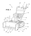
- a snow removal machine 10 has a body frame 11, left and right crawler belts 14, 14 mounted to the left and right sides of the body frame 11 via left and right drive wheels 12, 12 and driven wheels 13, 13 (the right drive and driven wheels 12, 13 are invisible in the figure), an engine 15 mounted to the body frame 11, a control handle 16 mounted rearward of the body frame 11, a control panel 17 provided to an upper portion of the control handle 16, left and right grips 18, 18 provided to rear ends of the control handle 16, and a snow removing plate 22 mounted to the front of the body frame 11 via a supporter 21.
- the snow removing plate 22 has a plate body 23 formed in a sectionally arc shape, reinforcing plates 26, 27 mounted to left and right ends 24, 25 of the plate body 23, a guiding/gap-closing member 31 and a scraper 32 mounted to a lower end portion of the plate body 23.
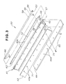
- the snow removing plate 22 is shown in perspective.
- the reinforcing plate 26 is attached to the left end 24 of the plate body 23.
- the guiding/gap-closing member 31 and the scraper 32 are attached to the lower end portion of the plate body 23.
- the snow removing plate 22 is symmetrical with respect to the centerline C.
- the plate body 23 has a closing member mounting part 33 at its lower end portion.
- the scraper 32 has a polygonal prism member 41 rotatably mounted to the snow removing plate 22, a first blade 42, a second blade 43, and a third blade 44 mounted to the polygonal prism member 41, and a rotation prevention member 45 for preventing rotation of the polygonal prism member 41.
- Reference numeral 46 denotes a ring.
- the rotation prevention member 45 includes a fixed plate 51 mounted to the reinforcing plate 26, a spindle retaining part 52 provided at a lower portion of the fixed plate 51, and a pin 53 to be inserted into the spindle retaining part 52.
- the fixed plate 51 is mounted to the reinforcing plate 26 with a plurality of bolts 54.
- Another rotation prevention member 45 is provided on the right side of the scraper 32, including a fixed plate 51 mounted to the reinforcing plate 27 (See FIG. 1), a spindle retaining part 52 and a pin 53.
- the spindle retaining part 52 has a pinhole 55 for receiving the pin 53.
- the polygonal prism member 41 has a body 56 of a generally triangular prism made from a steel material in this embodiment.
- a hole 57 is formed centrally of the body 56 in the longitudinal direction.
- a spindle 58 is inserted into the hole 57 and fixed to the body 56 by welding.
- the body 56 has a first surface 61, a second surface 62 and a third surface 63 which constitute the outer periphery thereof. Those surfaces are in a curved shape.
- the surfaces 61, 62 and 63 are formed with a plurality of female threads 64, respectively.
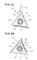
- the spindle 58 has, at each of the opposite ends, as shown in FIGS. 5A and 5B, a first angle setting hole 66, a second angle setting hole 67, and a third angle setting hole 68 provided as through holes, which are arranged at intervals of 120 degrees.
- the first blade 42, the second blade 43, and the third blade 44 are made from different kinds of material. Specifically, the first blade 42 is made from a steel material, the second blade 43 a resin material, and the third blade 44 rubber.
- the first blade 42 has a plurality of mounting holes 42a corresponding to the female threads 64 formed in the polygonal prism member 41, and is fixed to the first surface 61 of the polygonal prism member 41 with bolts 65 screwed through the mounting holes 42a into the female threads 64.
- the first blade 42 has a cutting edge 71 in the longitudinal direction.
- the second blade 43 has a plurality of mounting holes 43a corresponding to the female threads 64 and is fixed to the second surface 62 of the polygonal prism member 41 with bolts 65 screwed through the mounting holes 43a.
- the second blade 43 has a cutting edge 72 in the longitudinal direction.
- the third blade 44 has a plurality of mounting holes 44a corresponding to the female threads 64 and is fixed to the third surface 63 of the polygonal prism member 41 with bolts 65 screwed through the mounting holes 44a.
- the third blade 44 has a cutting edge 73 in the longitudinal direction.
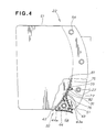
- FIG. 4 showing in side elevation the snow removing plate 22, with the scraper 32 and its surroundings shown in cross-section.
- the scraper 32 is mounted to a rear lower portion of the snow removing plate 22.
- the guiding/gap-closing member 31 is mounted to the closing member mounting part 33.
- the guiding/gap-closing member 31 has an upper-half mounting part 75 mounted to the closing member mounting part 33 with bolts 77, and a lower-half seat part 76.
- the guiding/gap-closing member 31 is mounted to the closing member mounting part 33 in a manner that a surface 82 of the guiding/gap-closing member 31 is coplanar with a surface 81 of the snow removing plate 22.
- the upper edge of the first blade 42 of the scraper 32 substantially abuts against the lower edge of the seat part 76.
- the seat part 76 also substantially abuts against the second blade 43 and the third blade 44 when the scraper 32 is rotated as described later.
- FIG. 5A shows that one of the three blades 42, 43 and 44 attached to the scraper 32 is selected for use in accordance with the state of snow on a road surface.
- the first angle setting hole 66, the second angle setting hole 67, and the third angle setting hole 68 are provided in the spindle 58 with 120 degree pitches as described above.
- the pin 53 is inserted into the spindle retaining part 52, passing through the first angle setting hole 66, the first blade 42 of steel material is selected and locked for use.
- the pin 53 is pulled out as shown by arrow 2 ⁇ to release the lock, thereby making the scraper 32 rotatable.
- FIG. 5B shows that the scraper 32 is rotated counterclockwise in the figure (in the direction of arrow 3 ⁇ ) at a predetermined angle, making the second angle setting hole 67 communicate with the pinhole 55.
- the pin 53 is inserted into the spindle retaining part 52, passing through the second angle setting hole 67 as shown by arrow 4 ⁇ . In this state, the second blade 43 of resin material is selected and is locked for use.
- the pin 53 is pulled out and inserted similarly.
- the scraper 32 can be rotated for blade change. This facilitates the change of blades of the scraper 32.
- the snow removal machine 10 is propelled (in the direction of arrow 5 ⁇ ) with the scraper 32 cutting through snow S on road surface R, scraping the snow S for removal.
- the first blade 42 of the scraper 32 is used to relatively easily scrape hardened snow with the cutting edge 71 of steel.
- the scraper 32 can thus handle hardened snow.
- the seat part 76 of the guiding/gap-closing member 31 When the seat part 76 of the guiding/gap-closing member 31 is made to substantially abut against the scraper 32, closing a gap between the scraper 32 and the snow removing plate 22, any gap hardly remains between the scraper 32 and the plate body 23. As a result, the snow removing plate 22 can remove snow without leaking rearward, thereby improving efficiency in snow removing operation.
- the guiding/gap-closing member 31 also substantially abuts at the seat part 76 against the second blade 43.
- the guiding/gap-closing member 31 is mounted to the closing member mounting part 33 at the lower end of the snow removing plate 22, and the surface 82 of the guiding/gap-closing member 31 is set coplanar with the surface 81 of the snow removing plate 22, and the guiding/gap-closing member 31 guides the transfer of snow S from the scraper 32 to the snow removing plate 22 as shown by arrow 6 ⁇ , the snow S can be smoothly transferred, resulting in improved snow removing performance of the machine 10.
- the scraper 32 is rotated counterclockwise (in the direction of arrow 3 ⁇ ), the first blade 42 being replaced with the second blade 43.
- the second blade 43 comes into contact with the seat part 76 of the guiding/gap-closing member 31.
- the guiding/gap-closing member 31 bends as shown by arrow 7 ⁇ , avoiding interfering with the scraper 32, and thereby not preventing the rotation of the scraper 32.
- the blade of the scraper 32 is changed to the second blade 43 with the cutting edge 72 of resin for removing snow on sidewalk H surfaced with a relatively sensitive material such as tiles or lumber.
- the cutting edge 72 is resiliently deformed, reducing pushing force F, and thereby causing no scratches on the sensitive surface of the sidewalk H.
- the cutting edge 73 of rubber can scrape relatively hard snow, and scraping noise can be reduced. This allows snow removal with the machine to be performed even during early mornings and late nights without annoyance.
- the scraper 32 can efficiently remove snow of different states, from hardened snow to soft snow, alone, while avoiding scratching the surface of a roadway or sidewalk, thereby improving the snow removing performance of the machine 10.
- FIGS. 2 to 5B of the first embodiment Like elements as in FIGS. 2 to 5B of the first embodiment are referred with like reference numerals to omit the description thereof.
- FIG. 7 shows a scraper 32A according to the second embodiment having all blades made from the same material. Specifically, a first blade 42, a second blade 42, and a third blade 42 are all made of steel material. These three blades 42, 42, 42 are provided on a polygonal prism member 41A.
- the scraper 32A has a positioning hole 84 formed in an end face of the polygonal prism member 41A (See FIG. 8) and a rotation prevention member 45A.
- the rotation prevention member 45A includes a fixed plate 51, a supporting member 85 attached to the fixed plate 51, a locking bolt 86, and mounting bolts 87, 87.
- the supporting member 85 is fitted into a central hole 57 of the polygonal prism member 41A, a pin 88 of the locking bolt 86 is fitted into the positioning hole 84, and the mounting bolts 87 are tightened, thereby attaching the scraper 32A to the snow removing plate 22.
- the three blades of the scraper 32A are made of the same steel material, if the first blade 42 is deformed or damaged, rotation of the scraper 32A is all that is needed to replace the blade with the second blade 42 attached to a second surface 62. This enables replacement with a new blade of the same material to occur in a short time, resulting in very easy blade change.
- the three blades are made of the same steel material. These blades may be made of resin material, rubber, or other material.
- the polygonal prism member 41 having the blades of different kinds of material attached thereto and the rotation prevention member 45A using the bolts as shown in FIGS. 7 and 8 may be combined. Also, the pin 53 and the polygonal prism member 41A having the blades of the same material attached thereto may be combined.
- the scraper has a polygonal prism member (41, 41A) rotatably mountable to the snow removing plate and a plurality of blades (42, 43, 44) detachably attached to respective surfaces (61, 62, 63) of the polygonal prism member.
- the polygonal prism member is rotated to select one of the blades for use in accordance with snow quality or the state of a road surface.
- a rotation prevention member (45, 45A) prevents rotation of the polygonal prism member.
Landscapes
- Engineering & Computer Science (AREA)
- Architecture (AREA)
- Civil Engineering (AREA)
- Structural Engineering (AREA)
- Cleaning Of Streets, Tracks, Or Beaches (AREA)
Applications Claiming Priority (2)
| Application Number | Priority Date | Filing Date | Title |
|---|---|---|---|
| JP2000381434 | 2000-12-15 | ||
| JP2000381434A JP4450401B2 (ja) | 2000-12-15 | 2000-12-15 | 除雪機のスクレーパ |
Publications (3)
| Publication Number | Publication Date |
|---|---|
| EP1215338A2 true EP1215338A2 (de) | 2002-06-19 |
| EP1215338A3 EP1215338A3 (de) | 2003-11-05 |
| EP1215338B1 EP1215338B1 (de) | 2009-12-02 |
Family
ID=18849430
Family Applications (1)
| Application Number | Title | Priority Date | Filing Date |
|---|---|---|---|
| EP01129539A Expired - Lifetime EP1215338B1 (de) | 2000-12-15 | 2001-12-11 | Schürfleiste für eine Schneeräumvorrichtung |
Country Status (6)
| Country | Link |
|---|---|
| US (1) | US6612050B2 (de) |
| EP (1) | EP1215338B1 (de) |
| JP (1) | JP4450401B2 (de) |
| CA (1) | CA2364879C (de) |
| DE (1) | DE60140653D1 (de) |
| NO (1) | NO335078B1 (de) |
Families Citing this family (40)
| Publication number | Priority date | Publication date | Assignee | Title |
|---|---|---|---|---|
| US7627965B2 (en) | 2001-11-12 | 2009-12-08 | Agri-Cover, Inc. | Plow blade having integrally formed attachment channel |
| US7676964B2 (en) | 2001-11-12 | 2010-03-16 | Agri-Cover, Inc. | Snow plow having wear minimizing apparatus |
| US7735247B2 (en) | 2001-11-12 | 2010-06-15 | Agri-Cover, Inc. | Snow plow for all terrain vehicle |
| US7743534B2 (en) | 2001-11-12 | 2010-06-29 | Agri-Cover, Inc. | Snow plow having two-piece mold board |
| US7784199B2 (en) | 2001-11-12 | 2010-08-31 | Agri-Cover, Inc. | Snow plow having pivotal mounting apparatus |
| US6817118B2 (en) | 2001-11-12 | 2004-11-16 | Charles M. Schmeichel | Self-adjusting snow plow |
| US7472499B2 (en) * | 2001-11-12 | 2009-01-06 | Agri-Cover, Inc. | Snow plow having pivoting mechanism |
| US7676963B2 (en) | 2001-11-12 | 2010-03-16 | Agri-Cover, Inc. | Snow plow including mold board having back plate |
| US7681335B2 (en) | 2001-11-12 | 2010-03-23 | Agri-Cover, Inc. | Snow plow having attachable biasing member |
| US7676962B2 (en) | 2001-11-12 | 2010-03-16 | Agri-Cover, Inc. | Snow plow having reinforced mold board |
| US7669353B2 (en) | 2001-11-12 | 2010-03-02 | Agri-Cover, Inc. | Snow plow having hitch tongue connecting member |
| US8875419B2 (en) | 2001-11-12 | 2014-11-04 | Agri-Cover, Inc. | Snow plow |
| US7735245B2 (en) | 2001-11-12 | 2010-06-15 | Agri-Cover, Inc. | Snow plow having catch structure |
| US7707753B2 (en) | 2001-11-12 | 2010-05-04 | Agri-Cover, Inc. | Multifunctional plow blade positioning apparatus and method |
| ATE447894T1 (de) * | 2002-07-19 | 2009-11-15 | Interventional Spine Inc | Vorrichtung zur wirbelsäulenfixierung |
| US8037625B2 (en) | 2003-03-31 | 2011-10-18 | Agri-Cover, Inc. | Snow plow having pivotal mounting apparatus |
| US7198687B2 (en) * | 2003-05-01 | 2007-04-03 | Giles A. Hill, III | Squeegee blade |
| US20050178029A1 (en) * | 2003-07-23 | 2005-08-18 | Craig Wightman | Attachment for a plow |
| US20050126051A1 (en) * | 2003-12-16 | 2005-06-16 | Jrb Attachments, Llc | Material pusher with improved structure |
| USD512443S1 (en) | 2004-06-09 | 2005-12-06 | Jrb Attachments, Llc | Sidewall for snow pusher |
| USD511174S1 (en) | 2004-06-09 | 2005-11-01 | Jrb Attachments, Llc | Snow pusher sidewall gusset |
| USD511173S1 (en) | 2004-06-09 | 2005-11-01 | Jrb Attachments, Llc | Snow pusher with sidewall gusset |
| CA2566993C (en) | 2005-11-03 | 2012-10-02 | Pro-Tech Manufacturing And Distribution, Inc. | Reversible snow pusher and coupler |
| CN101457518A (zh) * | 2008-10-21 | 2009-06-17 | 宋树建 | 一种安装在机动车上的扫雪装置 |
| EP2751339A4 (de) | 2011-08-31 | 2015-02-25 | Husqvarna Consumer Outdoor Products Na Inc | Hintere abschirmung für ein schneeräumfahrzeug |
| KR101249392B1 (ko) | 2011-12-19 | 2013-04-03 | 이리중 | 트랙터용 제설장치 |
| US9151006B2 (en) | 2012-02-09 | 2015-10-06 | Pro-Tech Manufacturing And Distribution, Inc. | Material pusher with control system |
| US8955238B1 (en) | 2013-03-06 | 2015-02-17 | John R. Castruccio | Adjustable plow blade |
| US9243376B2 (en) | 2013-06-14 | 2016-01-26 | Pro-Tech Manufacturing And Distribution, Inc. | Surface compliant front-pivoting wear shoes for snow pusher |
| US9938669B2 (en) | 2014-10-16 | 2018-04-10 | Nordco Inc. | Roadworthy rail ballast regulator |
| US10227751B2 (en) * | 2015-01-15 | 2019-03-12 | WJN Enterprises, Inc. | Sectional plow |
| CA2881150C (en) * | 2015-02-04 | 2019-01-15 | David Lorne Stoddart | Snow removal device comprising a pushing element with convex end portions and a scraping flange |
| JP6293705B2 (ja) * | 2015-06-03 | 2018-03-14 | 株式会社協和機械製作所 | 除雪用装置のカッティングエッジ着脱機構 |
| US10472783B2 (en) * | 2016-03-02 | 2019-11-12 | The Toro Company | Four wheel drive, skid steer snow vehicle with snow plow blade |
| JP6095826B1 (ja) * | 2016-04-11 | 2017-03-15 | 株式会社エポック社 | 溶着性ビーズ玩具用スクレイパー |
| US10422106B2 (en) * | 2017-06-30 | 2019-09-24 | Deere & Company | Removable wiper wall |
| US10851508B2 (en) | 2017-12-11 | 2020-12-01 | Pro-Tech Manufacturing And Distribution, Inc. | Material pusher with floating coupling and modular composite scraping edge |
| US20190330814A1 (en) * | 2018-04-30 | 2019-10-31 | Ozcan Yildiz | Shovel pusher and related systems and methods |
| US11214936B2 (en) | 2018-07-10 | 2022-01-04 | Venture Products, Inc. | Power unit with salt spreader and salt spreader for use therewith |
| US12595636B2 (en) | 2022-07-19 | 2026-04-07 | Bourgault Machines Inc. | Back-drag bucket accessory |
Citations (2)
| Publication number | Priority date | Publication date | Assignee | Title |
|---|---|---|---|---|
| JPS5134105A (ja) | 1974-07-15 | 1976-03-23 | Lummus Co | Ensokatankasuisonoseizoho |
| JPS5214347A (en) | 1975-07-25 | 1977-02-03 | Hitachi Ltd | Field emission electron gun |
Family Cites Families (6)
| Publication number | Priority date | Publication date | Assignee | Title |
|---|---|---|---|---|
| US3089264A (en) * | 1961-04-20 | 1963-05-14 | Sperry Rand Corp | Trip mechanism for rotary multiple blade scraper |
| DE1929177C3 (de) * | 1969-06-09 | 1978-04-20 | Reissinger, Gottfried, Dr., 8124 St Heinrich | Straßenräumgerät |
| DE2853126C2 (de) * | 1978-12-08 | 1980-08-21 | Gottfried Dr. Reissinger | Straßenräumgerät |
| US4570366A (en) * | 1984-08-10 | 1986-02-18 | Yost Kenneth J | Snowplow and blade having triangular rotatable cutting block teeth |
| US5611157A (en) * | 1993-10-05 | 1997-03-18 | F & B Enterprises, Inc. | Wear pad assembly |
| US5471770A (en) * | 1993-10-05 | 1995-12-05 | F&B Enterprises, Inc. | Rubberized wear pad assembly and method of making same |
-
2000
- 2000-12-15 JP JP2000381434A patent/JP4450401B2/ja not_active Expired - Fee Related
-
2001
- 2001-12-10 CA CA002364879A patent/CA2364879C/en not_active Expired - Fee Related
- 2001-12-11 EP EP01129539A patent/EP1215338B1/de not_active Expired - Lifetime
- 2001-12-11 DE DE60140653T patent/DE60140653D1/de not_active Expired - Lifetime
- 2001-12-13 US US10/016,829 patent/US6612050B2/en not_active Expired - Fee Related
- 2001-12-14 NO NO20016112A patent/NO335078B1/no not_active IP Right Cessation
Patent Citations (2)
| Publication number | Priority date | Publication date | Assignee | Title |
|---|---|---|---|---|
| JPS5134105A (ja) | 1974-07-15 | 1976-03-23 | Lummus Co | Ensokatankasuisonoseizoho |
| JPS5214347A (en) | 1975-07-25 | 1977-02-03 | Hitachi Ltd | Field emission electron gun |
Also Published As
| Publication number | Publication date |
|---|---|
| CA2364879C (en) | 2006-05-16 |
| CA2364879A1 (en) | 2002-06-15 |
| JP2002180432A (ja) | 2002-06-26 |
| NO20016112D0 (no) | 2001-12-14 |
| US6612050B2 (en) | 2003-09-02 |
| EP1215338B1 (de) | 2009-12-02 |
| NO335078B1 (no) | 2014-09-08 |
| NO20016112L (no) | 2002-06-17 |
| DE60140653D1 (de) | 2010-01-14 |
| US20020073581A1 (en) | 2002-06-20 |
| JP4450401B2 (ja) | 2010-04-14 |
| EP1215338A3 (de) | 2003-11-05 |
Similar Documents
| Publication | Publication Date | Title |
|---|---|---|
| EP1215338A2 (de) | Schürfleiste für eine Schneeräumvorrichtung | |
| US6112438A (en) | Snow plow | |
| US5536073A (en) | Road milling drum assembly and method of milling | |
| US6618965B1 (en) | Cushion stop and method for absorbing bidirectional impact of snow plow blade tripping | |
| US9243376B2 (en) | Surface compliant front-pivoting wear shoes for snow pusher | |
| CA2975113A1 (en) | Elastomeric plow edge | |
| CA2080655A1 (en) | Blades for snow-removal vehicles and vehicles therewith | |
| US10851507B2 (en) | Material pusher with floating coupler | |
| CA2505708C (en) | Cutting edge for a v-blade snowplow | |
| US6315056B1 (en) | Resilient scraping blade attachment | |
| MXPA01011207A (es) | Raspador de hielo que tiene herramientas no giratorias con piezas de insercion de corte, protegidas. | |
| EP0836660B1 (de) | Vorrichtung zum herstellen eines halbrohres aus schnee | |
| RU2202675C2 (ru) | Держатель режущей пластины для снегоочистительного устройства | |
| US11486106B2 (en) | Brush retrofit for a snow removal vehicle | |
| KR20140004723U (ko) | 차체 연결용 그레이더 | |
| CN219410696U (zh) | 一种除雪铲冰车的铲刀结构 | |
| US12595636B2 (en) | Back-drag bucket accessory | |
| CA3168237C (en) | Back-drag bucket accessory | |
| IE990281A1 (en) | Apparatus for Spreading a Quantity of Particulate Material | |
| KR100722717B1 (ko) | 제설기 | |
| US20220349156A1 (en) | Ejection paddle | |
| JP2003023802A (ja) | サブソイラ作業機 | |
| JPS636244Y2 (de) | ||
| HK1025799A (en) | Device for cleaning road edges |
Legal Events
| Date | Code | Title | Description |
|---|---|---|---|
| PUAI | Public reference made under article 153(3) epc to a published international application that has entered the european phase |
Free format text: ORIGINAL CODE: 0009012 |
|
| AK | Designated contracting states |
Kind code of ref document: A2 Designated state(s): AT BE CH CY DE DK ES FI FR GB GR IE IT LI LU MC NL PT SE TR |
|
| AX | Request for extension of the european patent |
Free format text: AL;LT;LV;MK;RO;SI |
|
| PUAL | Search report despatched |
Free format text: ORIGINAL CODE: 0009013 |
|
| AK | Designated contracting states |
Kind code of ref document: A3 Designated state(s): AT BE CH CY DE DK ES FI FR GB GR IE IT LI LU MC NL PT SE TR |
|
| AX | Request for extension of the european patent |
Extension state: AL LT LV MK RO SI |
|
| 17P | Request for examination filed |
Effective date: 20031222 |
|
| AKX | Designation fees paid |
Designated state(s): CH DE LI SE |
|
| 17Q | First examination report despatched |
Effective date: 20050913 |
|
| 17Q | First examination report despatched |
Effective date: 20050913 |
|
| 17Q | First examination report despatched |
Effective date: 20050913 |
|
| GRAP | Despatch of communication of intention to grant a patent |
Free format text: ORIGINAL CODE: EPIDOSNIGR1 |
|
| GRAS | Grant fee paid |
Free format text: ORIGINAL CODE: EPIDOSNIGR3 |
|
| GRAA | (expected) grant |
Free format text: ORIGINAL CODE: 0009210 |
|
| AK | Designated contracting states |
Kind code of ref document: B1 Designated state(s): CH DE LI SE |
|
| REG | Reference to a national code |
Ref country code: CH Ref legal event code: NV Representative=s name: BOHEST AG Ref country code: CH Ref legal event code: EP |
|
| REF | Corresponds to: |
Ref document number: 60140653 Country of ref document: DE Date of ref document: 20100114 Kind code of ref document: P |
|
| REG | Reference to a national code |
Ref country code: SE Ref legal event code: TRGR |
|
| PLBE | No opposition filed within time limit |
Free format text: ORIGINAL CODE: 0009261 |
|
| STAA | Information on the status of an ep patent application or granted ep patent |
Free format text: STATUS: NO OPPOSITION FILED WITHIN TIME LIMIT |
|
| 26N | No opposition filed |
Effective date: 20100903 |
|
| REG | Reference to a national code |
Ref country code: CH Ref legal event code: PCAR Free format text: NEW ADDRESS: HOLBEINSTRASSE 36-38, 4051 BASEL (CH) |
|
| PGFP | Annual fee paid to national office [announced via postgrant information from national office to epo] |
Ref country code: SE Payment date: 20141211 Year of fee payment: 14 Ref country code: CH Payment date: 20141212 Year of fee payment: 14 Ref country code: DE Payment date: 20141202 Year of fee payment: 14 |
|
| REG | Reference to a national code |
Ref country code: DE Ref legal event code: R119 Ref document number: 60140653 Country of ref document: DE |
|
| REG | Reference to a national code |
Ref country code: CH Ref legal event code: PL |
|
| REG | Reference to a national code |
Ref country code: SE Ref legal event code: EUG |
|
| PG25 | Lapsed in a contracting state [announced via postgrant information from national office to epo] |
Ref country code: SE Free format text: LAPSE BECAUSE OF NON-PAYMENT OF DUE FEES Effective date: 20151212 |
|
| PG25 | Lapsed in a contracting state [announced via postgrant information from national office to epo] |
Ref country code: DE Free format text: LAPSE BECAUSE OF NON-PAYMENT OF DUE FEES Effective date: 20160701 Ref country code: LI Free format text: LAPSE BECAUSE OF NON-PAYMENT OF DUE FEES Effective date: 20151231 Ref country code: CH Free format text: LAPSE BECAUSE OF NON-PAYMENT OF DUE FEES Effective date: 20151231 |