EP1215401A2 - Dispositif d'assemblage d'éléments de structure - Google Patents
Dispositif d'assemblage d'éléments de structure Download PDFInfo
- Publication number
- EP1215401A2 EP1215401A2 EP01126810A EP01126810A EP1215401A2 EP 1215401 A2 EP1215401 A2 EP 1215401A2 EP 01126810 A EP01126810 A EP 01126810A EP 01126810 A EP01126810 A EP 01126810A EP 1215401 A2 EP1215401 A2 EP 1215401A2
- Authority
- EP
- European Patent Office
- Prior art keywords
- spacer
- base part
- stop
- shoulder
- socket
- Prior art date
- Legal status (The legal status is an assumption and is not a legal conclusion. Google has not performed a legal analysis and makes no representation as to the accuracy of the status listed.)
- Granted
Links
- 125000006850 spacer group Chemical group 0.000 claims abstract description 73
- 239000002184 metal Substances 0.000 claims description 4
- 230000002093 peripheral effect Effects 0.000 claims description 3
- 230000000295 complement effect Effects 0.000 claims 1
- 210000000078 claw Anatomy 0.000 description 3
- 230000000694 effects Effects 0.000 description 2
- 230000037431 insertion Effects 0.000 description 1
- 238000003780 insertion Methods 0.000 description 1
Images

Classifications
-
- F—MECHANICAL ENGINEERING; LIGHTING; HEATING; WEAPONS; BLASTING
- F16—ENGINEERING ELEMENTS AND UNITS; GENERAL MEASURES FOR PRODUCING AND MAINTAINING EFFECTIVE FUNCTIONING OF MACHINES OR INSTALLATIONS; THERMAL INSULATION IN GENERAL
- F16B—DEVICES FOR FASTENING OR SECURING CONSTRUCTIONAL ELEMENTS OR MACHINE PARTS TOGETHER, e.g. NAILS, BOLTS, CIRCLIPS, CLAMPS, CLIPS OR WEDGES; JOINTS OR JOINTING
- F16B5/00—Joining sheets or plates, e.g. panels, to one another or to strips or bars parallel to them
- F16B5/02—Joining sheets or plates, e.g. panels, to one another or to strips or bars parallel to them by means of fastening members using screw-thread
- F16B5/0283—Joining sheets or plates, e.g. panels, to one another or to strips or bars parallel to them by means of fastening members using screw-thread with an externally threaded sleeve around the neck or the head of the screw-threaded element for adjustably fastening a plate or frame or the like to a fixed element
-
- F—MECHANICAL ENGINEERING; LIGHTING; HEATING; WEAPONS; BLASTING
- F16—ENGINEERING ELEMENTS AND UNITS; GENERAL MEASURES FOR PRODUCING AND MAINTAINING EFFECTIVE FUNCTIONING OF MACHINES OR INSTALLATIONS; THERMAL INSULATION IN GENERAL
- F16B—DEVICES FOR FASTENING OR SECURING CONSTRUCTIONAL ELEMENTS OR MACHINE PARTS TOGETHER, e.g. NAILS, BOLTS, CIRCLIPS, CLAMPS, CLIPS OR WEDGES; JOINTS OR JOINTING
- F16B5/00—Joining sheets or plates, e.g. panels, to one another or to strips or bars parallel to them
- F16B5/02—Joining sheets or plates, e.g. panels, to one another or to strips or bars parallel to them by means of fastening members using screw-thread
- F16B5/0216—Joining sheets or plates, e.g. panels, to one another or to strips or bars parallel to them by means of fastening members using screw-thread the position of the plates to be connected being adjustable
- F16B5/0233—Joining sheets or plates, e.g. panels, to one another or to strips or bars parallel to them by means of fastening members using screw-thread the position of the plates to be connected being adjustable allowing for adjustment perpendicular to the plane of the plates
-
- Y—GENERAL TAGGING OF NEW TECHNOLOGICAL DEVELOPMENTS; GENERAL TAGGING OF CROSS-SECTIONAL TECHNOLOGIES SPANNING OVER SEVERAL SECTIONS OF THE IPC; TECHNICAL SUBJECTS COVERED BY FORMER USPC CROSS-REFERENCE ART COLLECTIONS [XRACs] AND DIGESTS
- Y10—TECHNICAL SUBJECTS COVERED BY FORMER USPC
- Y10T—TECHNICAL SUBJECTS COVERED BY FORMER US CLASSIFICATION
- Y10T403/00—Joints and connections
- Y10T403/33—Transverse rod to spaced plate surfaces
-
- Y—GENERAL TAGGING OF NEW TECHNOLOGICAL DEVELOPMENTS; GENERAL TAGGING OF CROSS-SECTIONAL TECHNOLOGIES SPANNING OVER SEVERAL SECTIONS OF THE IPC; TECHNICAL SUBJECTS COVERED BY FORMER USPC CROSS-REFERENCE ART COLLECTIONS [XRACs] AND DIGESTS
- Y10—TECHNICAL SUBJECTS COVERED BY FORMER USPC
- Y10T—TECHNICAL SUBJECTS COVERED BY FORMER US CLASSIFICATION
- Y10T403/00—Joints and connections
- Y10T403/70—Interfitted members
- Y10T403/7062—Clamped members
- Y10T403/7064—Clamped members by wedge or cam
- Y10T403/7066—Clamped members by wedge or cam having actuator
- Y10T403/7067—Threaded actuator
Definitions
- the invention relates to a device for connecting components, with a on the one component arranged base part, a spacer that with the base part is in threaded engagement and with one end at the other Component supports, and a frictionally inserted through the spacer Connecting screw.
- a known device of this type is described in EP-B-0 176 663 and serves two components arranged at a certain distance from each other to connect using the connecting screw, without the components at Tighten the connecting screw.
- the connecting screw is inserted, for example, through the component located on the spacer should support, and is then in an internal thread of the other, with the base part connected component screwed. During this screwing-in movement the spacer frictionally taken.
- the thread between the spacers and base part is a left hand thread so that the spacer continues is screwed out of the base part and through the head of the connecting screw held component comes up until this component finally against the face of the spacer.
- the spacer is not in this case or is difficult to access, it is difficult to engage the thread between the spacer and the base part.
- the spacer is normally in the delivery state of the connecting device completely screwed into the base part.
- a connecting device known in which the spacer in this position on a Stop abuts and also by a resilient tongue in position is held.
- the resistance of this tongue has to be overcome leave when the connecting screw is screwed in. So it is not excluded that the spacer before using the connector due to improper handling or due to vibrations completely detaches from the base part, so that the parts of the connecting device fall apart and get lost.
- the object of the invention is therefore a device of the aforementioned To create the way in which the spacer and the base part held together captively are.
- This object is achieved in that the movement of the spacer relative to the base part in one direction by one at the end of the Threaded portion of the spacer formed shoulder is limited axially on one only after the spacer and base part have been assembled effective stop of the base part.
- the spacer first screw into the base part and then the stop is effective to be left, so that the spacer is not completely out again unscrew the base part.
- the relative movement of the spacer and base part through normal Stops are limited so that the spacer is not completely can be screwed through the base part. In this way, spacers and base part held captive after assembly.
- the one that takes effect only after assembly Stop by a spring element projecting radially inwards from the base part, for example in the form of a resilient tongue, which when Screwing in the spacer evades and then locking behind whose shoulder lays.
- the stop is rigidly formed on a socket, into which a threaded bushing of the base part is pressed.
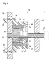
- Fig. 1 two plate-shaped components 10, 12 are shown, which are connected by a connecting device 14 to be connected to each other at a distance.
- the Connection device 14 is formed by a device 10 held on the component Base part 16, a spacer 18 screwed into the base part 16 and a connecting screw 20 which passes through the component 12 and in a center hole of the spacer 18 is inserted and upon completion the connection is screwed into a threaded bore 22 of the component 10 becomes.
- the base part 16 has a threaded bushing 24 made of metal, which is located on the component 10 supports and has knurling on the outer circumference, on the version 26 is pressed from plastic.
- the socket 26 forms two claws 28, with which the base part 16 is non-rotatably clipped onto the component 10.
- the spacer 18 is made entirely of metal.
- the threaded bush 24 of the base part and the spacer stand together by a left-hand thread 30 engaged.
- a spring ring 32 is pressed into the center bore of the spacer 18, which is a non-positive connection to the external thread of the connecting screw 20 manufactures.
- the spacer 18 is taken in the direction of rotation, while the base part 16 is held in rotation by the claws 28. by virtue of the left-hand thread therefore becomes the spacer 18 from the base part 16 unscrewed so that it moves axially towards the component 12, which in turn through the head of the connecting screw 20 against the spacer is pressed.
- the left-hand thread 30 of the spacer 18 is at one end, on the right in the figure 1, bounded by a shoulder 34.
- the socket 26 forms on the inner peripheral edge a circumferential collar 36 on which one end of the threaded bushing 24 supports.
- This collar 36 projects at at least one circumferential point a resilient tongue 38 to the inside.
- This tongue 38 forms a stop, which interacts with shoulder 34 and thus the maximum extension of the spacer 18 limited.
- the spacer 18 has a radially projecting flange 40, which is a contact surface for the component 12 forms when the components 10 and 12 by the connecting screw 20th are tense with each other.
- the closes The outer surface of the flange 40 is flush with the end face of the base part 16.
- a projection 42 extending radially from the edge of the flange 40 lies against one inwardly projecting stop 44 of the base part 16. The stop 44 thus prevents the spacer 18 in the screwing direction of the connecting screw 20 seen rotated to the left.
- the spacer can be 18 not beyond the position shown in FIG. 1 in the direction adjust to component 10.
- the spacer 18 When assembling the connector, the spacer 18 however from the right side in FIG. 1 into the threaded bushing 24 of the base part be screwed in.
- the elastic tongue 38 is initially after bent inside so that it dodges the spacer 18.
- the tongue 38 In the further Screwing in the spacer, the tongue 38 then slides on the external thread along the spacer and it finally slides over shoulder 34 away so that it can spring back to its original position, in which is effective as a stop for the shoulder 34.
- FIGS. 2 and 3 show a connecting device 46 as a further example, in which the connecting screw 20 is screwed in from the opposite end becomes.
- the component 10 in this case has a keyhole shape Opening 48 with two diametrically opposite protuberances 50 to accommodate the claws 28.
- the circular inner part of the opening 48 is covered by a washer 52 on which the head of the connecting screw 20 and support the threaded bushing 24 of the base part 16.
- the threaded bushing 24 and the spacer 18 have one in this case Right-hand thread, so that the spacer 18 to the right in Figure 2, in the direction extends to the component 12 when the connecting screw 20 is clockwise is rotated.
- Figure 2 shows the spacer 18 already in the extended state in which the shoulder 34 has almost reached the stop position.
- the attack in this case, however, the version 26 is not supported by a resilient tongue, but formed by a rigid projection 54.
- the one on the spacer 18th trained flange 40 which in this case has a smaller diameter, has at one point on its circumference a recess 56 through which the Projection 54 can pass axially.
- the threaded bushing is first 24 and the spacer screwed together before the threaded bushing 24 is pressed into the socket 26.
- the spacer 18 can are therefore screwed into the threaded bushing 24 from the right in FIG approximately the screw-in position shown in FIG. 2 is reached.
- the spacer 18 and the threaded bush 14 together from the inserted into the socket 26 on the left-hand side in FIG.
- the spacer 18 held in an angular position in which the projection 54 through the recess 56 can pass through.
- the threaded bush 24 with its knurled outer peripheral edge pressed into the socket 26.
- the spacer 18 screwed deeper into the threaded bushing 24 until its opposite End faces are flush with the corresponding end faces of the base part 16.
- Figure 3 shows part of the end face of the flange 40 and part of a on the socket 26 formed collar 58 which surrounds this flange 40.
- Recess 56 rotated relative to the projection 54 of the base part.
- the left flank of the recess 56 is a radial from Edge of the flange 40 formed outwardly projecting projection 60.
- To the inner circumferential surface of the collar 58 are an inwardly projecting stop 62 and a locking spring 64 formed in a bridge-like manner.
- the flange 40 enters the collar 58.
- the lead 60 first glides over the overcoming a certain latching resistance Detent spring 64 away and then strikes the stop 62. That way the further screwing-in movement of the spacer 18 is limited.
- the Detent spring 64 becomes the spacer in the position reached with minimal Axial dimension kept, and it is prevented that the spacer due to blocked by vibrations by itself.
- the force of the detent spring 64 is so dimensioned that it is due to the frictional connection between the connecting screw 20 and the spacer can be overcome if the connecting screw 20 is screwed in. With this screwing-in movement 3, the spacer 18 rotates to the left in the view according to FIG that the projection 60 moves away from the stop 62.
Landscapes
- Engineering & Computer Science (AREA)
- General Engineering & Computer Science (AREA)
- Mechanical Engineering (AREA)
- Bolts, Nuts, And Washers (AREA)
- Mutual Connection Of Rods And Tubes (AREA)
- Connection Of Plates (AREA)
- Slide Fasteners, Snap Fasteners, And Hook Fasteners (AREA)
Applications Claiming Priority (2)
| Application Number | Priority Date | Filing Date | Title |
|---|---|---|---|
| DE20021194U DE20021194U1 (de) | 2000-12-14 | 2000-12-14 | Vorrichtung zum Verbinden von Bauteilen |
| DE20021194U | 2000-12-14 |
Publications (3)
| Publication Number | Publication Date |
|---|---|
| EP1215401A2 true EP1215401A2 (fr) | 2002-06-19 |
| EP1215401A3 EP1215401A3 (fr) | 2002-10-23 |
| EP1215401B1 EP1215401B1 (fr) | 2005-01-12 |
Family
ID=7950063
Family Applications (1)
| Application Number | Title | Priority Date | Filing Date |
|---|---|---|---|
| EP01126810A Expired - Lifetime EP1215401B1 (fr) | 2000-12-14 | 2001-11-10 | Dispositif d'assemblage d'éléments de structure |
Country Status (5)
| Country | Link |
|---|---|
| US (1) | US6585447B2 (fr) |
| EP (1) | EP1215401B1 (fr) |
| JP (1) | JP4105430B2 (fr) |
| DE (2) | DE20021194U1 (fr) |
| ES (1) | ES2233553T3 (fr) |
Cited By (6)
| Publication number | Priority date | Publication date | Assignee | Title |
|---|---|---|---|---|
| WO2005005844A1 (fr) * | 2003-06-25 | 2005-01-20 | The Gates Corporation | Raccord |
| WO2010066363A1 (fr) * | 2008-12-12 | 2010-06-17 | Hans Und Ottmar Binder Gbr | Dispositif d'écartement et système de fixation avec dispositif d'écartement |
| DE202011052036U1 (de) | 2011-11-18 | 2013-02-20 | Jörg Schwarzbich | Toleranzausgleichselement |
| DE202012102440U1 (de) | 2012-07-03 | 2013-10-07 | Jörg Schwarzbich | Toleranzausgleichselement |
| WO2019149500A1 (fr) * | 2018-02-01 | 2019-08-08 | Witte Automotive Gmbh | Dispositif de compensation de tolérances |
| JP2019529831A (ja) * | 2016-09-22 | 2019-10-17 | シュヴァルツビッチ, ヨルグSCHWARZBICH, Jorg | 公差補償要素 |
Families Citing this family (32)
| Publication number | Priority date | Publication date | Assignee | Title |
|---|---|---|---|---|
| US6884014B2 (en) * | 2001-04-23 | 2005-04-26 | The Gates Corporation | Tolerance compensating mounting device |
| JP4028968B2 (ja) * | 2001-05-23 | 2008-01-09 | 本田技研工業株式会社 | 車両のプレート取付構造。 |
| US6869245B2 (en) * | 2001-10-03 | 2005-03-22 | Michel Lewis Cabiran | High strength detachable cylinder-to-plate joint for tables, furniture, and other static structures |
| US7001098B2 (en) * | 2003-06-20 | 2006-02-21 | Taiwan Semiconductor Manufacturing Co., Ltd. | Lock structure and method for using thereof |
| DE20313241U1 (de) * | 2003-08-27 | 2004-12-30 | Schwarzbich, Jörg | Vorrichtung zum Verbinden von Bauteilen mit Blindnietbefestigung |
| JP4371897B2 (ja) * | 2003-09-04 | 2009-11-25 | 西川ゴム工業株式会社 | 車両用バッテリーの固定構造 |
| DE20314003U1 (de) * | 2003-09-09 | 2003-11-13 | Böllhoff GmbH, 33649 Bielefeld | Toleranzausgleichsanordnung |
| AU2006226870A1 (en) * | 2005-03-23 | 2006-09-28 | Bell Helicopter Textron, Inc. | Apparatus for joining members and assembly thereof |
| DE202005009017U1 (de) * | 2005-06-08 | 2005-08-25 | Böllhoff Verbindungstechnik GmbH | Toleranzausgleichsanordnung aus Kunststoff |
| EP1907711A1 (fr) * | 2005-07-11 | 2008-04-09 | The Gates Corporation | Connecteur de compensation de tolerance |
| US20070017720A1 (en) * | 2005-07-25 | 2007-01-25 | Kazuhiro Fujii | Battery device of vehicle power supply |
| DE202005016823U1 (de) * | 2005-10-26 | 2006-02-09 | Böllhoff Verbindungstechnik GmbH | Befestigungseinrichtung mit Toleranzausgleich |
| US7987637B2 (en) * | 2006-09-25 | 2011-08-02 | Smith Patrick J | Adjustable shim |
| KR101086609B1 (ko) * | 2009-06-01 | 2011-11-23 | 현대자동차주식회사 | 카울 크로스바 마운팅 조립체 |
| JP5030004B2 (ja) * | 2009-11-25 | 2012-09-19 | Necアクセステクニカ株式会社 | 座金及び座金付ネジ、これらを用いた固定構造及び固定方法並びに固定解除方法 |
| DE102010018471A1 (de) * | 2010-04-28 | 2011-11-03 | Gm Global Technology Operations Llc (N.D.Ges.D. Staates Delaware) | Schraubverbindungsvorrichtung zur Herstellung einer toleranzausgleichenden Schraubverbindung |
| CN102418733B (zh) * | 2010-09-28 | 2013-08-07 | 富泰华工业(深圳)有限公司 | 高度调整机构及使用其对电子装置进行组装的组装方法 |
| DE102011003541A1 (de) * | 2011-01-31 | 2012-08-02 | BSH Bosch und Siemens Hausgeräte GmbH | Einbau-Haushaltsgerät, insbesondere Geschirrspülmaschine |
| EP2941572A1 (fr) * | 2013-01-02 | 2015-11-11 | Illinois Tool Works Inc. | Ensemble de fixation à écrous de compensation |
| DE102013109036A1 (de) * | 2013-08-21 | 2015-02-26 | Heiko Schmidt | Verfahren zum Verbinden von Bauteilen sowie Baugruppe |
| US9297408B2 (en) * | 2014-01-30 | 2016-03-29 | GM Global Technology Operations LLC | Coupling spacer, assembly, and method |
| EP3126685B1 (fr) * | 2014-03-31 | 2021-02-17 | Böllhoff Verbindungstechnik GmbH | Dispositif d'assemblage, procédé d'assemblage et procédé de fabrication afférent |
| US9359012B2 (en) * | 2014-04-14 | 2016-06-07 | Ford Global Technologies, Llc | Tolerance compensator for a vehicle frame |
| DE102016110754A1 (de) * | 2016-06-10 | 2017-12-14 | Huf Hülsbeck & Fürst Gmbh & Co. Kg | Befestigungsvorrichtung zum Befestigen eines ersten Bauteils an einem zweiten Bauteil |
| DE102016212549A1 (de) | 2016-07-11 | 2018-01-11 | Springfix Befestigungstechnik Gmbh | Vorrichtung zum Festlegen an einem Bauteil |
| CN121701541A (zh) * | 2017-08-29 | 2026-03-20 | 伊利诺斯工具制品有限公司 | 具有延长公差补偿和更简单快速紧固的公差补偿紧固装置 |
| CN110939645B (zh) * | 2018-09-21 | 2023-02-21 | 伊利诺斯工具制品有限公司 | 螺母紧固件 |
| CN112065841A (zh) * | 2019-06-11 | 2020-12-11 | 长城汽车股份有限公司 | 间隙补偿装置、方法及车辆 |
| US20210140455A1 (en) * | 2019-10-14 | 2021-05-13 | Geolyn Holdings LLC | Apparatus and method for anchoring fasteners |
| DE102020204180A1 (de) * | 2020-03-31 | 2021-09-30 | Witte Automotive Gmbh | Befestigungselement |
| DE102020133763A1 (de) | 2020-12-16 | 2022-06-23 | Böllhoff Verbindungstechnik GmbH | Toleranzausgleichsanordnung |
| US11746587B1 (en) * | 2022-08-25 | 2023-09-05 | Chad Joseph Hildreth | Doorframe fastening device and method of use |
Citations (1)
| Publication number | Priority date | Publication date | Assignee | Title |
|---|---|---|---|---|
| EP0176663B1 (fr) | 1984-10-03 | 1988-07-27 | Ewald Witte & Co. | Dispositif pour la jonction à haubanage de pièces situées à distance l'une de l'autre |
Family Cites Families (13)
| Publication number | Priority date | Publication date | Assignee | Title |
|---|---|---|---|---|
| US3014563A (en) | 1957-06-12 | 1961-12-26 | Gen Motors Corp | Anchor assembly |
| US3332182A (en) | 1964-12-03 | 1967-07-25 | Interstate Ind Inc | Partition stud and spring assembly |
| US4373309A (en) | 1978-09-11 | 1983-02-15 | Gelu Reutlinger Steinwerk Gerhard Lutz Gmbh | Supporting bolt |
| US4934861A (en) | 1988-10-24 | 1990-06-19 | The University Of Alabama | Attachment apparatus for external stores on thin-wall poles |
| US5271700A (en) | 1989-05-16 | 1993-12-21 | Acb | Fixing member |
| US5288191A (en) * | 1991-08-26 | 1994-02-22 | Ewald Witte Gmbh & Co. Kg | Device for the clamping attachment of spaced structural parts |
| ES2077143T3 (es) * | 1991-11-22 | 1995-11-16 | Werner Simon | Unidad de union a rosca. |
| FR2691513B1 (fr) | 1992-05-20 | 1995-11-10 | Peugeot | Dispositif de fixation d'un element sur une structure, avec rattrapage automatique de jeu. |
| JP2864925B2 (ja) * | 1992-12-28 | 1999-03-08 | 日産自動車株式会社 | ステアリングメンバの取付構造 |
| DE59706039D1 (de) * | 1997-06-18 | 2002-02-21 | Werner Simon | Schraubeinheit |
| CN1096535C (zh) | 1997-06-27 | 2002-12-18 | 株式会社皆荣技术 | 混凝土砌块的连接结构及其所用的连接器 |
| DE29807967U1 (de) | 1998-05-04 | 1999-09-23 | Schwarzbich, Jörg, 33615 Bielefeld | Vorrichtung zum Verbinden von Bauteilen |
| DE19839710B4 (de) | 1998-09-01 | 2005-04-28 | Webasto Ag Fahrzeugtechnik | Vorrichtung zum verspannenden Verbinden von zwei in Abstand befindlichen Bauteilen |
-
2000
- 2000-12-14 DE DE20021194U patent/DE20021194U1/de not_active Expired - Lifetime
-
2001
- 2001-11-10 DE DE50105056T patent/DE50105056D1/de not_active Expired - Lifetime
- 2001-11-10 ES ES01126810T patent/ES2233553T3/es not_active Expired - Lifetime
- 2001-11-10 EP EP01126810A patent/EP1215401B1/fr not_active Expired - Lifetime
- 2001-12-12 JP JP2001378619A patent/JP4105430B2/ja not_active Expired - Lifetime
- 2001-12-13 US US10/066,082 patent/US6585447B2/en not_active Expired - Lifetime
Patent Citations (1)
| Publication number | Priority date | Publication date | Assignee | Title |
|---|---|---|---|---|
| EP0176663B1 (fr) | 1984-10-03 | 1988-07-27 | Ewald Witte & Co. | Dispositif pour la jonction à haubanage de pièces situées à distance l'une de l'autre |
Cited By (15)
| Publication number | Priority date | Publication date | Assignee | Title |
|---|---|---|---|---|
| WO2005005844A1 (fr) * | 2003-06-25 | 2005-01-20 | The Gates Corporation | Raccord |
| US8764337B2 (en) | 2008-12-12 | 2014-07-01 | Hans Und Ottmar Binder Gbr | Distance device and fastening system having distance device |
| WO2010066363A1 (fr) * | 2008-12-12 | 2010-06-17 | Hans Und Ottmar Binder Gbr | Dispositif d'écartement et système de fixation avec dispositif d'écartement |
| CN103122897B (zh) * | 2011-11-18 | 2015-09-16 | 约尔格·施瓦茨比奇 | 公差补偿部件 |
| CN103122897A (zh) * | 2011-11-18 | 2013-05-29 | 约尔格·施瓦茨比奇 | 公差补偿部件 |
| DE102012110352A1 (de) | 2011-11-18 | 2013-05-23 | Jörg Schwarzbich | Toleranzausgleichselement |
| US9074614B2 (en) | 2011-11-18 | 2015-07-07 | Jörg Schwarzbich | Tolerance compensation member |
| DE202011052036U1 (de) | 2011-11-18 | 2013-02-20 | Jörg Schwarzbich | Toleranzausgleichselement |
| DE102012110352B4 (de) * | 2011-11-18 | 2016-09-01 | Jörg Schwarzbich | Toleranzausgleichselement |
| DE202012102440U1 (de) | 2012-07-03 | 2013-10-07 | Jörg Schwarzbich | Toleranzausgleichselement |
| WO2014005899A1 (fr) | 2012-07-03 | 2014-01-09 | Schwarzbich Joerg | Élément de compensation de tolérances |
| US9464659B2 (en) | 2012-07-03 | 2016-10-11 | Jörg Schwarzbich | Tolerance-equalizing element |
| JP2019529831A (ja) * | 2016-09-22 | 2019-10-17 | シュヴァルツビッチ, ヨルグSCHWARZBICH, Jorg | 公差補償要素 |
| WO2019149500A1 (fr) * | 2018-02-01 | 2019-08-08 | Witte Automotive Gmbh | Dispositif de compensation de tolérances |
| US12312013B2 (en) | 2018-02-01 | 2025-05-27 | Witte Automotive Gmbh | Device for compensating for tolerances |
Also Published As
| Publication number | Publication date |
|---|---|
| US6585447B2 (en) | 2003-07-01 |
| EP1215401B1 (fr) | 2005-01-12 |
| JP4105430B2 (ja) | 2008-06-25 |
| DE50105056D1 (de) | 2005-02-17 |
| EP1215401A3 (fr) | 2002-10-23 |
| JP2002227811A (ja) | 2002-08-14 |
| ES2233553T3 (es) | 2005-06-16 |
| DE20021194U1 (de) | 2002-04-18 |
| US20020076269A1 (en) | 2002-06-20 |
Similar Documents
| Publication | Publication Date | Title |
|---|---|---|
| EP1215401B1 (fr) | Dispositif d'assemblage d'éléments de structure | |
| EP1180605B1 (fr) | Dispositif pour assembler des elements constitutifs | |
| DE69305057T2 (de) | Elastischer Ring mit Fertiganzeige für eine Verbindung | |
| EP0176663B1 (fr) | Dispositif pour la jonction à haubanage de pièces situées à distance l'une de l'autre | |
| EP1510701B1 (fr) | Dispositif d'assemblage de pièces par fixation avec rivet aveugle | |
| DE102007037242B4 (de) | Befestigungseinrichtung mit Toleranzausgleich | |
| DE19839342C2 (de) | Gerätesteckverbinder | |
| EP3209888B1 (fr) | Dispositif de fixation rapide, procédé d'assemblage de deux éléments au moyen du dispositif de fixation rapide, et procédé de fabrication afférent | |
| EP2851596B1 (fr) | Élément de traversée murale pour une conduite de fluide et traversée murale | |
| WO2013150016A1 (fr) | Système de fixation à compensation de tolérances et procédé de prémontage et montage | |
| DE19924502A1 (de) | Schraube mit Hülse | |
| WO2020200776A1 (fr) | Élément de réglage en plusieurs parties pour un agencement de compensation de tolérances | |
| EP1277971A1 (fr) | Cheville expansible imperdable | |
| DE102021105786A1 (de) | Toleranzausgleichsanordnung | |
| DE102007003789A1 (de) | Sicherungselement | |
| EP0153677A1 (fr) | Obturateur à fermeture automatique pour réservoir de carburant | |
| EP3394495B1 (fr) | Disque denté doté de dents de retenue à plusieurs éléments jointifs | |
| EP4110140B1 (fr) | Dispositif de réglage de meubles, et procédé d'installation d'un dispositif de réglage | |
| CH680306A5 (fr) | ||
| DE20016150U1 (de) | Vorrichtung zum Verbinden von Bauteilen | |
| DE4309494C2 (de) | Staubsaugerschlauch | |
| DE102020133001B3 (de) | Einpress-Gerätesteckverbinder zum Pressfügen mit einem Metallgehäuse | |
| DE20013863U1 (de) | Vorrichtung zum Verbinden von Bauteilen | |
| DE20101088U1 (de) | Vorrichtung zum Verbinden von Bauteilen | |
| EP4328472A1 (fr) | Ensemble soupape à bride et bride |
Legal Events
| Date | Code | Title | Description |
|---|---|---|---|
| PUAI | Public reference made under article 153(3) epc to a published international application that has entered the european phase |
Free format text: ORIGINAL CODE: 0009012 |
|
| AK | Designated contracting states |
Kind code of ref document: A2 Designated state(s): AT BE CH CY DE DK ES FI FR GB GR IE IT LI LU MC NL PT SE TR |
|
| AX | Request for extension of the european patent |
Free format text: AL;LT;LV;MK;RO;SI |
|
| PUAL | Search report despatched |
Free format text: ORIGINAL CODE: 0009013 |
|
| AK | Designated contracting states |
Kind code of ref document: A3 Designated state(s): AT BE CH CY DE DK ES FI FR GB GR IE IT LI LU MC NL PT SE TR |
|
| AX | Request for extension of the european patent |
Free format text: AL;LT;LV;MK;RO;SI |
|
| 17P | Request for examination filed |
Effective date: 20030410 |
|
| AKX | Designation fees paid |
Designated state(s): DE ES FR GB IT SE |
|
| 17Q | First examination report despatched |
Effective date: 20031202 |
|
| GRAP | Despatch of communication of intention to grant a patent |
Free format text: ORIGINAL CODE: EPIDOSNIGR1 |
|
| GRAS | Grant fee paid |
Free format text: ORIGINAL CODE: EPIDOSNIGR3 |
|
| GRAA | (expected) grant |
Free format text: ORIGINAL CODE: 0009210 |
|
| AK | Designated contracting states |
Kind code of ref document: B1 Designated state(s): DE ES FR GB IT SE |
|
| REG | Reference to a national code |
Ref country code: GB Ref legal event code: FG4D Free format text: NOT ENGLISH |
|
| REG | Reference to a national code |
Ref country code: SE Ref legal event code: TRGR |
|
| REF | Corresponds to: |
Ref document number: 50105056 Country of ref document: DE Date of ref document: 20050217 Kind code of ref document: P |
|
| REG | Reference to a national code |
Ref country code: IE Ref legal event code: FG4D Free format text: GERMAN |
|
| GBT | Gb: translation of ep patent filed (gb section 77(6)(a)/1977) |
Effective date: 20050324 |
|
| REG | Reference to a national code |
Ref country code: ES Ref legal event code: FG2A Ref document number: 2233553 Country of ref document: ES Kind code of ref document: T3 |
|
| PLBE | No opposition filed within time limit |
Free format text: ORIGINAL CODE: 0009261 |
|
| STAA | Information on the status of an ep patent application or granted ep patent |
Free format text: STATUS: NO OPPOSITION FILED WITHIN TIME LIMIT |
|
| ET | Fr: translation filed | ||
| 26N | No opposition filed |
Effective date: 20051013 |
|
| PGFP | Annual fee paid to national office [announced via postgrant information from national office to epo] |
Ref country code: IT Payment date: 20101025 Year of fee payment: 10 Ref country code: GB Payment date: 20101105 Year of fee payment: 10 |
|
| PGFP | Annual fee paid to national office [announced via postgrant information from national office to epo] |
Ref country code: FR Payment date: 20111115 Year of fee payment: 11 Ref country code: ES Payment date: 20111024 Year of fee payment: 11 Ref country code: SE Payment date: 20111116 Year of fee payment: 11 |
|
| GBPC | Gb: european patent ceased through non-payment of renewal fee |
Effective date: 20121110 |
|
| PG25 | Lapsed in a contracting state [announced via postgrant information from national office to epo] |
Ref country code: SE Free format text: LAPSE BECAUSE OF NON-PAYMENT OF DUE FEES Effective date: 20121111 |
|
| REG | Reference to a national code |
Ref country code: FR Ref legal event code: ST Effective date: 20130731 |
|
| PG25 | Lapsed in a contracting state [announced via postgrant information from national office to epo] |
Ref country code: IT Free format text: LAPSE BECAUSE OF NON-PAYMENT OF DUE FEES Effective date: 20121110 |
|
| REG | Reference to a national code |
Ref country code: DE Ref legal event code: R119 Ref document number: 50105056 Country of ref document: DE Effective date: 20130601 |
|
| PG25 | Lapsed in a contracting state [announced via postgrant information from national office to epo] |
Ref country code: DE Free format text: LAPSE BECAUSE OF NON-PAYMENT OF DUE FEES Effective date: 20130601 |
|
| REG | Reference to a national code |
Ref country code: DE Ref legal event code: R073 Ref document number: 50105056 Country of ref document: DE |
|
| REG | Reference to a national code |
Ref country code: DE Ref legal event code: R074 Ref document number: 50105056 Country of ref document: DE |
|
| PG25 | Lapsed in a contracting state [announced via postgrant information from national office to epo] |
Ref country code: FR Free format text: LAPSE BECAUSE OF NON-PAYMENT OF DUE FEES Effective date: 20121130 Ref country code: GB Free format text: LAPSE BECAUSE OF NON-PAYMENT OF DUE FEES Effective date: 20121110 |
|
| REG | Reference to a national code |
Ref country code: DE Ref legal event code: R074 Ref document number: 50105056 Country of ref document: DE Effective date: 20131122 Ref country code: DE Ref legal event code: R074 Ref document number: 50105056 Country of ref document: DE Effective date: 20131125 |
|
| PGRI | Patent reinstated in contracting state [announced from national office to epo] |
Ref country code: DE Effective date: 20131122 |
|
| REG | Reference to a national code |
Ref country code: ES Ref legal event code: FD2A Effective date: 20140305 |
|
| PG25 | Lapsed in a contracting state [announced via postgrant information from national office to epo] |
Ref country code: ES Free format text: LAPSE BECAUSE OF NON-PAYMENT OF DUE FEES Effective date: 20121111 |
|
| REG | Reference to a national code |
Ref country code: DE Ref legal event code: R039 Ref document number: 50105056 Country of ref document: DE Ref country code: DE Ref legal event code: R008 Ref document number: 50105056 Country of ref document: DE |
|
| REG | Reference to a national code |
Ref country code: DE Ref legal event code: R040 Ref document number: 50105056 Country of ref document: DE |
|
| PGFP | Annual fee paid to national office [announced via postgrant information from national office to epo] |
Ref country code: DE Payment date: 20201126 Year of fee payment: 20 |
|
| REG | Reference to a national code |
Ref country code: DE Ref legal event code: R071 Ref document number: 50105056 Country of ref document: DE |