EP1215412A2 - Unité piston-cylindre avec unité de réglage - Google Patents
Unité piston-cylindre avec unité de réglage Download PDFInfo
- Publication number
- EP1215412A2 EP1215412A2 EP01129752A EP01129752A EP1215412A2 EP 1215412 A2 EP1215412 A2 EP 1215412A2 EP 01129752 A EP01129752 A EP 01129752A EP 01129752 A EP01129752 A EP 01129752A EP 1215412 A2 EP1215412 A2 EP 1215412A2
- Authority
- EP
- European Patent Office
- Prior art keywords
- piston
- cylinder unit
- cylinder
- piston rod
- unit according
- Prior art date
- Legal status (The legal status is an assumption and is not a legal conclusion. Google has not performed a legal analysis and makes no representation as to the accuracy of the status listed.)
- Granted
Links
- 230000005540 biological transmission Effects 0.000 claims abstract description 31
- 230000000712 assembly Effects 0.000 claims abstract description 5
- 238000000429 assembly Methods 0.000 claims abstract description 5
- 239000002775 capsule Substances 0.000 claims description 20
- 229920001971 elastomer Polymers 0.000 description 3
- 239000000806 elastomer Substances 0.000 description 3
- 230000004048 modification Effects 0.000 description 3
- 238000012986 modification Methods 0.000 description 3
- 238000010276 construction Methods 0.000 description 1
- 238000010586 diagram Methods 0.000 description 1
- 230000000694 effects Effects 0.000 description 1
- 238000007789 sealing Methods 0.000 description 1
- 238000005507 spraying Methods 0.000 description 1
- 238000004804 winding Methods 0.000 description 1
Images
Classifications
-
- F—MECHANICAL ENGINEERING; LIGHTING; HEATING; WEAPONS; BLASTING
- F16—ENGINEERING ELEMENTS AND UNITS; GENERAL MEASURES FOR PRODUCING AND MAINTAINING EFFECTIVE FUNCTIONING OF MACHINES OR INSTALLATIONS; THERMAL INSULATION IN GENERAL
- F16F—SPRINGS; SHOCK-ABSORBERS; MEANS FOR DAMPING VIBRATION
- F16F9/00—Springs, vibration-dampers, shock-absorbers, or similarly-constructed movement-dampers using a fluid or the equivalent as damping medium
- F16F9/32—Details
- F16F9/3207—Constructional features
-
- F—MECHANICAL ENGINEERING; LIGHTING; HEATING; WEAPONS; BLASTING
- F16—ENGINEERING ELEMENTS AND UNITS; GENERAL MEASURES FOR PRODUCING AND MAINTAINING EFFECTIVE FUNCTIONING OF MACHINES OR INSTALLATIONS; THERMAL INSULATION IN GENERAL
- F16F—SPRINGS; SHOCK-ABSORBERS; MEANS FOR DAMPING VIBRATION
- F16F9/00—Springs, vibration-dampers, shock-absorbers, or similarly-constructed movement-dampers using a fluid or the equivalent as damping medium
- F16F9/02—Springs, vibration-dampers, shock-absorbers, or similarly-constructed movement-dampers using a fluid or the equivalent as damping medium using gas only or vacuum
- F16F9/0209—Telescopic
- F16F9/0245—Means for adjusting the length of, or for locking, the spring or dampers
- F16F9/0263—Means for adjusting the length of, or for locking, the spring or dampers characterised by actuation means, e.g. manually-operated lever arrangement
Definitions
- the invention relates to a piston-cylinder unit in connection with an adjusting device according to the preamble of claim 1.
- FR 2 730 714 is a piston-cylinder unit in the form of a gas spring in connection with an adjustment device for opening and closing movement a vehicle door known.
- the adjustment device includes a Bowden cable, which is operated by a winding device.
- the Bowden cable is inside guided by a cylinder which has an axially movable piston rod.
- the adjusting device is a known per se in parallel Gas spring assigned, in the direction of extension of the piston rod of the adjusting device exercises a power.
- a disadvantage of this unit combination is the space required. In a motor vehicle there is only one for the gas spring anyway limited space. Furthermore, the costs for the adjustment device, but also the additional frictional forces on the piston and on the piston rod guide the adjustment device.
- the object of the present invention is to realize a gas spring in which the construction effort for the adjustment function is reduced.
- the object is achieved in that the force transmission means concentric on one of the two assemblies of the piston-cylinder unit attacks.
- the power transmission means centrally in the piston-cylinder unit connected.
- the advantage of this measure is that part of the power transmission means on the one hand protected inside the Piston-cylinder unit lies and on the other hand in the application, for example for furniture, design requirements are met.
- an extension is carried out on the piston rod, which protrudes from the end of the cylinder.
- the advantage of this measure is that an extension is easier to seal than the power transmission means, that, for example, from a Bowden cable or a threaded stand or one Rack is formed.
- the cylinder has a piston rod guide for the piston rod and a guide for the extension. So that the piston rod is guided particularly well radially.
- the extension optionally has a stroke limit stop for the piston rod on. This enables the stroke of the piston rod in various applications adapted with a single embodiment of the piston-cylinder unit and thus standardization can be achieved.
- the stroke limit stop is a sleeve formed.
- the sleeve is a Thread connection with the extension and thus continuously adjustable is.
- the piston rod is hollow and takes up a connection, on the one hand with the cylinder and on the other hand is connected to the power transmission means. Even at maximum When the piston rod is extended, there is still a section of the connection connection inside the hollow piston rod so that the connection port and the piston rod are very easy to seal against each other.
- connection port has a flange that is connected to the cylinder connected is.
- the flange on a bottom of the Cylinder is attached.
- the flange can be placed directly on the floor be and improve it in terms of mechanical strength.
- the Cylinder has a capsule element arranged concentrically to the piston rod, which receives the power transmission element, wherein the power transmission element through the hollow piston rod to an attachment point to be led.
- the advantage is achieved that the piston-cylinder unit as a simple shell for the power transmission element can be seen. consequently cannot have any transverse forces or other loads from the power transmission element be transferred to the piston-cylinder unit.
- the capsule element extends into the piston rod.
- the capsule element can with simple means against the ingress of operating medium from the Cylinders are sealed.
- the capsule element from a tube is formed.
- the piston rod telescopes simultaneously with the capsule element.
- the capsule element is on the bottom attached to the cylinder.
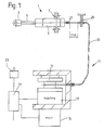
- Fig. 1 shows an actuation system that a piston-cylinder unit 1 in the Contains the design of a gas spring.
- the actuation system can serve as an example for the Opening and closing movement of a vehicle door or flap is used become.
- the piston-cylinder unit has a cylinder as an assembly 3 and as a second assembly via a piston rod 5, the piston rod is axially movable relative to the cylinder.
- the cylinder is with one gaseous pressure medium filled, so that an extension force on the piston rod is effective.
- Each of the two modules has a connection element 7; 9, wherein the cylinder-side connector 7 radially in the form of a Swivel bearing is executed. Based on the above Application example can the pivot bearing 7 on a vehicle body and the connection bearing 9 be attached to a vehicle hatch.
- the actuation system comprises an adjusting device 11 which a motor 13 as an actuator and a Bowden cable as a power transmission means 15.
- the actuator has a clutch 17 and a roll-up mechanism 19, which contains a spring, not shown, to rotate when the motor is uncoupled the reel mechanism.
- Control electronics 21 in connection with at least one sensor 23 detecting the movement of the flap influences the operation of the actuator.
- the piston-cylinder unit exerts an actuating force in the direction of extension of the piston rod 5 out.
- the actuator counteracts the force transmission means the actuating force of the piston-cylinder unit and leaves the piston rod again retract.
- the force transmission means or the Bowden cable is supported axially a stop 25 from. Between the stop and a connection connection 27 of the Bowden cable on the piston-cylinder unit 1 is a distance that corresponds at least to the stroke length of the piston rod.
- the invention is in no way limited to an actuator in the form of a Engine. You could also use a simple hand-operated crank. Also the power transmission means could be designed differently, for. B. a rack is used.
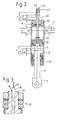
- Figure 2 is limited in its representation to the piston-cylinder unit 1.
- the piston rod 5 has a piston 29 which the cylinder in two working spaces 31; 33 divided. Extending from the piston an extension 35 through the work space 33 to the outside of the cylinder located connection port 27.
- the extension is such dimensioned that the connection connection even with the piston rod fully extended is not preloaded on the piston rod guide. Furthermore, takes effect the extension concentrically on the piston or the piston rod, so that at an adjustment force on the extension no lateral forces can occur.
- the connector 7 is a radial Swivel bearing executed.
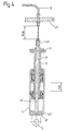
- the guide 39 could also be a pin joint 40, which contains a central channel 42, in which the extension 35 is displaceable, as is shown as a schematic diagram in FIG. 3.
- a piston rod guide 37 is available for the piston rod. Also the extension is centered in a guide 39 which has a seal 41, to seal the workspaces from the atmosphere.
- a stroke limit stop 43 is attached, with which the usable stroke length of the piston-cylinder unit is determined becomes.
- the stroke limit stop is formed by a sleeve, the different Can have lengths.
- the end distance a; b or c to guide the piston rod determines the stroke length of the piston-cylinder unit.
- the sleeve can also form a threaded connection 45 with the extension, so that the usable stroke length is infinitely adjustable within limits.
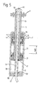
- Fig. 4 shows a modification of Fig. 2.
- the essential difference to Fig. 2 is that the piston rod 5 is hollow throughout and receives the connection terminal 27.
- the connection port has via a flange 47 which is attached to the bottom 49 of the cylinder.
- the length of the connection terminal 27 is dimensioned such that it is at every possible Stroke length of the piston rod extends beyond the open end of the piston rod.
- Not one Loss of operating medium occurs between the hollow ones Piston rod and the connection port 27 arranged the seal 41, which for the relative movement between the extension and the piston rod seals the necessary annular gap.
- the piston rod has a radial connector 9 in the form of a pivot bearing.
- the piston rod has a radial connector 9 in the form of a pivot bearing.
- the piston rod With an effective adjusting force from the Power transmission means 15 pulled in the direction of the piston.
- FIG. 5 shows a modification of FIG. 4.
- a capsule member 51 is used in the form of a tube that the Bottom 49 of the cylinder 3 penetrates and thus the possibility of implementation of the power transmission element 15 enables.
- the capsule element has an elastic bearing 53 which, for example can be formed by an elastomer ring 55.
- an elastomer ring offers the advantage of sealing the working space 33 in the area of a central one Opening 57 in the bottom for the capsule element.
- Spraying can be a simple one and yet durable and fluid-tight connection between the elastomer ring and the capsule element can be reached.
- the capsule element projects into the piston rod in every stroke position, starting from a certain extended position of the piston rod Capsule element related to the power transmission element.
- connection elements 7; 9 as radial Swivel bearing designed, although other connection types are possible are.
- the force transmission element 15 is directly on the element to be moved, for example the vehicle flap 59 connected to an attachment point 61.
- the piston-cylinder unit thus only serves as a shell that does not involve any forces of the power transmission element must take up.
- Another advantage of this solution is that the alignment of the piston-cylinder unit completely possible regardless of the direction of force of the force transmission element 15 is, d. H. one can, if one looks at the application example mentioned several times remains, either the cylinder 3 or the piston rod 5 articulated on the flap Fasten. For the functioning of the power transmission element arise thereby no differences.
Landscapes
- Engineering & Computer Science (AREA)
- General Engineering & Computer Science (AREA)
- Mechanical Engineering (AREA)
- Fluid-Damping Devices (AREA)
- Actuator (AREA)
Applications Claiming Priority (2)
| Application Number | Priority Date | Filing Date | Title |
|---|---|---|---|
| DE10062773A DE10062773C1 (de) | 2000-12-15 | 2000-12-15 | Kolben-Zylinderaggregat mit einer Verstelleinrichtung |
| DE10062773 | 2000-12-15 |
Publications (3)
| Publication Number | Publication Date |
|---|---|
| EP1215412A2 true EP1215412A2 (fr) | 2002-06-19 |
| EP1215412A3 EP1215412A3 (fr) | 2003-07-16 |
| EP1215412B1 EP1215412B1 (fr) | 2004-11-03 |
Family
ID=7667430
Family Applications (1)
| Application Number | Title | Priority Date | Filing Date |
|---|---|---|---|
| EP01129752A Expired - Lifetime EP1215412B1 (fr) | 2000-12-15 | 2001-12-13 | Unité piston-cylindre avec unité de réglage |
Country Status (5)
| Country | Link |
|---|---|
| US (1) | US20020069753A1 (fr) |
| EP (1) | EP1215412B1 (fr) |
| JP (1) | JP2002227907A (fr) |
| DE (2) | DE10062773C1 (fr) |
| ES (1) | ES2232561T3 (fr) |
Cited By (2)
| Publication number | Priority date | Publication date | Assignee | Title |
|---|---|---|---|---|
| WO2006056039A1 (fr) * | 2004-11-24 | 2006-06-01 | Magna Closures Inc. | Dispositif d'actionnement a energie auxiliaire pour panneau de fermeture d'un vehicule |
| CN107299806A (zh) * | 2017-06-23 | 2017-10-27 | 成都创科升电子科技有限责任公司 | 一种液压式引擎盖抬升装置 |
Families Citing this family (10)
| Publication number | Priority date | Publication date | Assignee | Title |
|---|---|---|---|---|
| US6707173B2 (en) * | 2001-10-26 | 2004-03-16 | Avm, Incorporated | Linear actuator for a powered vehicle lift gate |
| DE10221440A1 (de) * | 2002-05-15 | 2003-11-27 | Suspa Holding Gmbh | Kraftspeicher |
| US7034485B2 (en) * | 2004-09-24 | 2006-04-25 | Arvin Technologies, Inc. | Vehicle liftgate control system |
| US7648189B2 (en) | 2005-10-03 | 2010-01-19 | Magna Closures Inc. | Powered actuating device for a closure panel of a vehicle |
| US20080133089A1 (en) * | 2006-11-30 | 2008-06-05 | Ahmad Bayomy | Height-Adjusting Wheelchair |
| US9789964B2 (en) * | 2014-03-31 | 2017-10-17 | B/E Aerospace, Inc. | Electronically actuated cable release mechanism for adjustable aircraft passenger seat features and method therefor |
| CN106414239B (zh) * | 2014-03-31 | 2021-07-30 | Be航天公司 | 用于锁紧气弹簧的电子致动的机械电缆释放装置和方法 |
| WO2016133638A1 (fr) * | 2015-02-20 | 2016-08-25 | Zodiac Seats Us Llc | Système haptique : commande d'activation d'inclinaison |
| JP6912607B2 (ja) * | 2018-02-09 | 2021-08-04 | 株式会社オートネットワーク技術研究所 | アームレスト |
| US20210064096A1 (en) * | 2019-08-28 | 2021-03-04 | Intel Corporation | Infinite Holding Pivot Mechanisms for Dual Screen Systems |
Citations (1)
| Publication number | Priority date | Publication date | Assignee | Title |
|---|---|---|---|---|
| FR2730714A1 (fr) | 1995-02-16 | 1996-08-23 | Renault | Verin motorise, notamment pour dispositif de commande d'ouverture et de fermeture d'un hayon de vehicule automobile |
Family Cites Families (14)
| Publication number | Priority date | Publication date | Assignee | Title |
|---|---|---|---|---|
| DE8218079U1 (de) * | 1982-06-24 | 1983-01-05 | HPZ Hydropneumatische Zugfeder GmbH, 4422 Ahaus | Blockierbare Gasfeder |
| DE3329011A1 (de) * | 1983-08-11 | 1984-01-05 | Johannes Erhard, H. Waldenmaier Erben Süddeutsche Armaturenfabrik GmbH & Co, 7920 Heidenheim | Kolbenoelbremse fuer armaturen |
| US4741516A (en) * | 1984-06-28 | 1988-05-03 | Liquidspring Investors, Ltd. | Fluid suspension spring and damper for vehicle suspension system |
| US4854541A (en) * | 1988-08-08 | 1989-08-08 | Iowa State University Research Foundation, Inc. | Power line support |
| DE8815010U1 (de) * | 1988-12-02 | 1989-03-16 | Röder GmbH Sitzmöbelwerke, 60388 Frankfurt | Vorrichtung zum Betätigen des Auslösestößels einer längenverstellbaren Gasfeder |
| JP2506668Y2 (ja) * | 1989-12-26 | 1996-08-14 | アイシン精機株式会社 | バックドア自動開閉装置 |
| DE4124869A1 (de) * | 1991-07-26 | 1993-01-28 | Bayerische Motoren Werke Ag | Vorrichtung zum motor- und kraftbetaetigten bewegen einer klappe, insbesondere einer heckklappe fuer kraftfahrzeuge |
| DE4311625A1 (de) * | 1993-04-08 | 1994-10-13 | Stabilus Gmbh | Pneumatische, hydraulische oder hydropneumatische Verstelleinrichtung |
| DE9315245U1 (de) * | 1993-10-09 | 1994-01-05 | Suspa Compart Ag, 90518 Altdorf | Längenverstellbare Gasfeder |
| US5839230A (en) * | 1994-09-09 | 1998-11-24 | Licking; Michael A. | Window propelling system |
| US5531498A (en) * | 1994-12-01 | 1996-07-02 | Chrysler Corporation | Vehicle body with powered lift type tailgate |
| DE19515368A1 (de) * | 1995-05-02 | 1996-11-07 | Suspa Compart Ag | Längenverstellbare Gasfeder |
| DE29508612U1 (de) * | 1995-05-24 | 1995-08-17 | AKS Aktuelle Krankenpflege Systeme GmbH, 53842 Troisdorf | Bett mit verstellbarer Auflagefläche |
| DE19548139C2 (de) * | 1995-12-21 | 1998-09-24 | Stabilus Gmbh | Gasfeder mit einstellbarer Endposition |
-
2000
- 2000-12-15 DE DE10062773A patent/DE10062773C1/de not_active Expired - Fee Related
-
2001
- 2001-11-30 JP JP2001366669A patent/JP2002227907A/ja active Pending
- 2001-12-13 DE DE50104375T patent/DE50104375D1/de not_active Expired - Lifetime
- 2001-12-13 EP EP01129752A patent/EP1215412B1/fr not_active Expired - Lifetime
- 2001-12-13 ES ES01129752T patent/ES2232561T3/es not_active Expired - Lifetime
- 2001-12-17 US US10/024,684 patent/US20020069753A1/en not_active Abandoned
Patent Citations (1)
| Publication number | Priority date | Publication date | Assignee | Title |
|---|---|---|---|---|
| FR2730714A1 (fr) | 1995-02-16 | 1996-08-23 | Renault | Verin motorise, notamment pour dispositif de commande d'ouverture et de fermeture d'un hayon de vehicule automobile |
Cited By (2)
| Publication number | Priority date | Publication date | Assignee | Title |
|---|---|---|---|---|
| WO2006056039A1 (fr) * | 2004-11-24 | 2006-06-01 | Magna Closures Inc. | Dispositif d'actionnement a energie auxiliaire pour panneau de fermeture d'un vehicule |
| CN107299806A (zh) * | 2017-06-23 | 2017-10-27 | 成都创科升电子科技有限责任公司 | 一种液压式引擎盖抬升装置 |
Also Published As
| Publication number | Publication date |
|---|---|
| DE50104375D1 (de) | 2004-12-09 |
| ES2232561T3 (es) | 2005-06-01 |
| EP1215412B1 (fr) | 2004-11-03 |
| JP2002227907A (ja) | 2002-08-14 |
| DE10062773C1 (de) | 2002-07-25 |
| US20020069753A1 (en) | 2002-06-13 |
| EP1215412A3 (fr) | 2003-07-16 |
Similar Documents
| Publication | Publication Date | Title |
|---|---|---|
| DE19950582B9 (de) | Betätigungsvorrichtung für ein drehbares Verschlussteil eines Ventils | |
| EP2457754B1 (fr) | Actionneur de suspension | |
| EP1215412B1 (fr) | Unité piston-cylindre avec unité de réglage | |
| DE102016008306A1 (de) | Pleuel mit verstellbarer Pleuellänge | |
| EP0422338A2 (fr) | Amortisseur de vibrations à liquide | |
| DE10109954A1 (de) | Ventiltrieb einer Brennkraftmaschine | |
| AT395053B (de) | Sanitaerarmatur | |
| DE69307447T2 (de) | Lineares Verbindungsglied, welches selektiven Totgang ermöglicht | |
| DE102018120002B3 (de) | Verriegelungsmechanismus für längenveränderbare Pleuelstangen | |
| EP1253329B1 (fr) | Vérin à pression fluidique avec dispositif anti-rotation | |
| DE10038734C2 (de) | Gedämpfter Pneumatikzylinder zur Erzeugung einer konstanten langsamen linearen Antriebsbewegung | |
| DE19535755A1 (de) | Stelleinrichtung, insbesondere für die Betätigung einer Schaltwelle eines Schaltgetriebes für Kraftfahrzeuge | |
| DE102010025538B4 (de) | Stellvorrichtung | |
| DE102009053428A1 (de) | Stellvorrichtung zur Umwandlung einer rotatorischen Bewegung in eine lineare Bewegung | |
| DE102017107673A1 (de) | Pleuel für eine variable Verdichtung einer Brennkraftmaschine | |
| EP0987478B1 (fr) | Soupape électromagnétique | |
| DE19710574B4 (de) | Wegsensor | |
| DE19746828C2 (de) | Kolben-Zylinderaggregat | |
| DE2851291A1 (de) | Daempfungseinrichtung zur endabbremsung von kolben | |
| EP2564100A1 (fr) | Dispositif d'actionnement d'un élément rotatif de verrouillage d'une soupape | |
| DE102007055862A1 (de) | Verdrehsicherung mit Toleranzausgleich | |
| DE102020121518A1 (de) | Antriebsanordnung für eine Klappe eines Kraftfahrzeugs | |
| DE202016100452U1 (de) | Feldgerät | |
| DE4437169C1 (de) | Lenkventil mit geschlossener Mitte | |
| DE102017204346A1 (de) | Pedalkraftsimulationsanordnung sowie Kraftfahrzeug |
Legal Events
| Date | Code | Title | Description |
|---|---|---|---|
| PUAI | Public reference made under article 153(3) epc to a published international application that has entered the european phase |
Free format text: ORIGINAL CODE: 0009012 |
|
| AK | Designated contracting states |
Kind code of ref document: A2 Designated state(s): AT BE CH CY DE DK ES FI FR GB GR IE IT LI LU MC NL PT SE TR |
|
| AX | Request for extension of the european patent |
Free format text: AL;LT;LV;MK;RO;SI |
|
| PUAL | Search report despatched |
Free format text: ORIGINAL CODE: 0009013 |
|
| AK | Designated contracting states |
Designated state(s): AT BE CH CY DE DK ES FI FR GB GR IE IT LI LU MC NL PT SE TR |
|
| AX | Request for extension of the european patent |
Extension state: AL LT LV MK RO SI |
|
| 17P | Request for examination filed |
Effective date: 20030814 |
|
| 17Q | First examination report despatched |
Effective date: 20030916 |
|
| AKX | Designation fees paid |
Designated state(s): DE ES FR GB IT |
|
| GRAP | Despatch of communication of intention to grant a patent |
Free format text: ORIGINAL CODE: EPIDOSNIGR1 |
|
| GRAS | Grant fee paid |
Free format text: ORIGINAL CODE: EPIDOSNIGR3 |
|
| GRAA | (expected) grant |
Free format text: ORIGINAL CODE: 0009210 |
|
| AK | Designated contracting states |
Kind code of ref document: B1 Designated state(s): DE ES FR GB IT |
|
| REG | Reference to a national code |
Ref country code: GB Ref legal event code: FG4D Free format text: NOT ENGLISH |
|
| GBT | Gb: translation of ep patent filed (gb section 77(6)(a)/1977) | ||
| REF | Corresponds to: |
Ref document number: 50104375 Country of ref document: DE Date of ref document: 20041209 Kind code of ref document: P |
|
| REG | Reference to a national code |
Ref country code: IE Ref legal event code: FG4D Free format text: GERMAN |
|
| REG | Reference to a national code |
Ref country code: ES Ref legal event code: FG2A Ref document number: 2232561 Country of ref document: ES Kind code of ref document: T3 |
|
| REG | Reference to a national code |
Ref country code: IE Ref legal event code: FD4D |
|
| PLBE | No opposition filed within time limit |
Free format text: ORIGINAL CODE: 0009261 |
|
| STAA | Information on the status of an ep patent application or granted ep patent |
Free format text: STATUS: NO OPPOSITION FILED WITHIN TIME LIMIT |
|
| 26N | No opposition filed |
Effective date: 20050804 |
|
| ET | Fr: translation filed | ||
| PGFP | Annual fee paid to national office [announced via postgrant information from national office to epo] |
Ref country code: GB Payment date: 20061221 Year of fee payment: 6 |
|
| PGFP | Annual fee paid to national office [announced via postgrant information from national office to epo] |
Ref country code: ES Payment date: 20061228 Year of fee payment: 6 |
|
| PGFP | Annual fee paid to national office [announced via postgrant information from national office to epo] |
Ref country code: IT Payment date: 20061231 Year of fee payment: 6 |
|
| GBPC | Gb: european patent ceased through non-payment of renewal fee |
Effective date: 20071213 |
|
| PG25 | Lapsed in a contracting state [announced via postgrant information from national office to epo] |
Ref country code: GB Free format text: LAPSE BECAUSE OF NON-PAYMENT OF DUE FEES Effective date: 20071213 |
|
| REG | Reference to a national code |
Ref country code: ES Ref legal event code: FD2A Effective date: 20071214 |
|
| PG25 | Lapsed in a contracting state [announced via postgrant information from national office to epo] |
Ref country code: ES Free format text: LAPSE BECAUSE OF NON-PAYMENT OF DUE FEES Effective date: 20071214 |
|
| PGFP | Annual fee paid to national office [announced via postgrant information from national office to epo] |
Ref country code: FR Payment date: 20081212 Year of fee payment: 8 |
|
| PG25 | Lapsed in a contracting state [announced via postgrant information from national office to epo] |
Ref country code: IT Free format text: LAPSE BECAUSE OF NON-PAYMENT OF DUE FEES Effective date: 20071213 |
|
| REG | Reference to a national code |
Ref country code: FR Ref legal event code: ST Effective date: 20100831 |
|
| PG25 | Lapsed in a contracting state [announced via postgrant information from national office to epo] |
Ref country code: FR Free format text: LAPSE BECAUSE OF NON-PAYMENT OF DUE FEES Effective date: 20091231 |
|
| PGFP | Annual fee paid to national office [announced via postgrant information from national office to epo] |
Ref country code: DE Payment date: 20101231 Year of fee payment: 10 |
|
| REG | Reference to a national code |
Ref country code: DE Ref legal event code: R119 Ref document number: 50104375 Country of ref document: DE Effective date: 20120703 |
|
| PG25 | Lapsed in a contracting state [announced via postgrant information from national office to epo] |
Ref country code: DE Free format text: LAPSE BECAUSE OF NON-PAYMENT OF DUE FEES Effective date: 20120703 |