EP1215431A2 - Durchflussregelventil - Google Patents
Durchflussregelventil Download PDFInfo
- Publication number
- EP1215431A2 EP1215431A2 EP01124670A EP01124670A EP1215431A2 EP 1215431 A2 EP1215431 A2 EP 1215431A2 EP 01124670 A EP01124670 A EP 01124670A EP 01124670 A EP01124670 A EP 01124670A EP 1215431 A2 EP1215431 A2 EP 1215431A2
- Authority
- EP
- European Patent Office
- Prior art keywords
- cavity
- valve
- port
- wall
- conduit
- Prior art date
- Legal status (The legal status is an assumption and is not a legal conclusion. Google has not performed a legal analysis and makes no representation as to the accuracy of the status listed.)
- Withdrawn
Links
Images


Classifications
-
- F—MECHANICAL ENGINEERING; LIGHTING; HEATING; WEAPONS; BLASTING
- F16—ENGINEERING ELEMENTS AND UNITS; GENERAL MEASURES FOR PRODUCING AND MAINTAINING EFFECTIVE FUNCTIONING OF MACHINES OR INSTALLATIONS; THERMAL INSULATION IN GENERAL
- F16K—VALVES; TAPS; COCKS; ACTUATING-FLOATS; DEVICES FOR VENTING OR AERATING
- F16K47/00—Means in valves for absorbing fluid energy
- F16K47/08—Means in valves for absorbing fluid energy for decreasing pressure or noise level and having a throttling member separate from the closure member, e.g. screens, slots, labyrinths
- F16K47/10—Means in valves for absorbing fluid energy for decreasing pressure or noise level and having a throttling member separate from the closure member, e.g. screens, slots, labyrinths in which the medium in one direction must flow through the throttling channel, and in the other direction may flow through a much wider channel parallel to the throttling channel
Definitions
- the present invention relates generally to flow control valves, and more particularly to a flow control valve and related methods for use in fuel injectors for internal combustion engines.
- a conduit requires different flow restriction depending on the direction of flow through the conduit.
- flow control valves have been formed using a first passageway and a second passageway that were connected in parallel.
- the first passageway included a first check valve and a first flow restrictor.
- the second passageway included a second check valve and a second flow restrictor.
- the first check valve would allow the fluid flow to flow in a first direction through the first passageway.
- the second check valve would prevent flow from passing through the second passageway.
- the first flow restrictor would provide a first level of flow restriction.
- the first check valve would prevent flow through the first passageway and the second flow restrictor would allow flow through the second passageway.
- the second flow restrictor would provide a second level of flow restriction.
- the first flow restrictor and the second flow restrictor would provide two different levels of flow restriction.
- first and second parallel passageways and the check valves and flow restrictors required a large space. They could not be easily located in the small space within a hydraulic control system. Additionally, the first and second flow restrictors would clog with solid material being carried in the fluid flow.
- the present invention is directed toward overcoming one or more of the problems as set forth above.
- a valve comprises a housing having at least first and second walls that define a cavity therein.
- the cavity is configured such that a cross-sectional area of the cavity taken perpendicular to a longitudinal axis of the cavity decreases from the second wall to the first wall.
- a port is provided in the first wall for allowing material to enter or exit a cavity, and a port is provided in the second wall for allowing material to enter or exit the cavity.
- a flow restrictor disposed in the cavity.
- the valve described above comprises a flow control valve for a fuel injector.
- a method for controlling flow of fluid in a hydraulic device comprises providing a valve having a housing which defines a cavity therein, with the cavity having a first portion having a relatively large cross-sectional area taken perpendicular to a longitudinal axis of the cavity and a second portion having a relatively small cross-sectional area taken perpendicular to the longitudinal axis.
- the method further comprises flowing material through the cavity in a first direction which causes a flow restrictor disposed in the cavity to occupy a position substantially in the first portion of the cavity, whereby flow of the material in the first direction is relatively unrestricted.
- the method further comprises flowing material through the cavity in a second direction opposite the first direction which causes the flow restrictor to occupy a position substantially in the second portion of the cavity, whereby flow of the material in the second direction is relatively restricted.
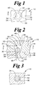
- FIG. 1 a top view of a valve or so-called ball reversal orifice 10, is shown.
- FIG. 2 is a cross-sectional view of the valve or ball reversal orifice 10 taken along line 2--2 of FIG. 1.
- FIG. 2 shows a first plate 12, a second plate 14, and a third plate 16.
- the plates 12, 14, and 16 cooperate to form a valve housing defining a cavity 18.
- the housing may be formed from fewer parts, such as by combining together one or more of the plates 12, 14, and 16 into a unitary part.
- the cavity 18 includes a first wall 20, a second wall 22, and a conical portion 24.
- the first wall 20 and the second wall 22 are connected to the conical portion 24.
- the first wall 20 is larger in area than the second wall 22.
- the first wall 20 of the cavity 18 is a portion of the surface 26 of the plate 12.
- the conical portion 24 of the cavity 18 is formed in the plate 14.
- the second wall 22 of the cavity 18 is a portion of
- FIG. 2 shows a port 32 in the first wall 20 of the cavity 18, and a port 34 in the second wall 22 of the cavity 18.
- a first conduit 36 is attached to the port 32, and a second conduit 38 is attached to the port 34.
- a center 40 of the port 32 is always offset from the centerline 44 of the ball 30.
- a center 42 of the port 34 is always offset from the centerline 44 of the ball 30.
- a longitudinal axis 46 of the first conduit 36 is always offset from the centerline 44 of the ball 30. This ensures that the ball 30 will never cover and close the port 32 or the port 34.
- a longitudinal axis 48 of the second conduit 38 is always offset from the centerline 44 of the ball 30. In this embodiment, the longitudinal axis 46 of the first conduit 36 is offset from the longitudinal axis 48 of the second conduit 38.
- Material 50 including fluid containing suspended particles may freely flow through the ports 32 and 34.
- FIG. 2 shows a ball location with material 50 flowing in a first direction through the first conduit 36, through the port 32, through the cavity 18, and exiting through the port 34 into the second conduit 38.
- the material 50 may be, e.g., a liquid, a hydraulic fluid, a gas, or a plurality small particles. The small particles may be suspended in the gas or liquid.
- FIG. 3 shows a cross-sectional view taken along line 3-3 of FIG. 2.
- a gap 52 is formed between the ball 30 and a frusto-conical portion 24. The material 50 flow is restricted as the material 50 flows through the gap 52.
- FIG. 4 shows the ball reversal orifice 10 with the material 50 flowing in a second direction through the second conduit 38, through the port 34, through the cavity 18, and exiting through the port 32 into the first conduit 36.
- the material flow pushes the ball 30 against the first wall 20 of the cavity 18.
- FIG. 5 shows a cross-sectional view taken along line 5--5 of FIG. 4.
- a gap 54 is formed between the ball 30 and a frusto-conical portion 24.
- the gap 54 is larger in flow area than the flow area created by gap 52 (FIG. 3). Therefore, there is greater restriction to material 50 flow when the material 50 flow is in the first direction, from the port 32 to port 34, then when the material 50 flow is in the second direction, from port 34 to 32.
- FIG. 4 illustrates a longitudinal axis 64 of the cavity 18.
- FIG. 6 shows another embodiment of the valve or ball reversal orifice 10A of the present invention.
- a port 32A is located in the first wall 20A of the cavity 18.
- a port 34A is located in the second wall 22A of the cavity 18.
- a first conduit 36A is attached to the port 32A, and a second conduit 38A is attached to the port 34A.
- a center 40A of the port 32A is always offset from the centerline 44 of the ball 30.
- a center 42A of the port 34A is always offset from the centerline 44 of the ball 30.
- a longitudinal axis 46A of the first conduit 36A is always offset from the centerline 44 of the ball 30.
- a longitudinal axis 48A is always offset from the centerline 44 of the ball 30.
- the longitudinal axis 46A of the first conduit 36A, the center 40A of the port 32A, the longitudinal axis 48A of the second conduit 38A, and the center 42A of the port 34A all in-line. However, this in-line axis is always offset from the centerline 44 of the ball 30.
- FIG. 7 shows a top view of the ball reversal orifice 10B.
- FIG. 8 is a cross-sectional view of the ball reversal orifice 10B taken along line 8--8 of FIG. 7.
- FIG. 8 shows a first plate 12B, a second plate 14B, and a third plate 16B.
- a cavity 18B includes a first wall 20B, a second wall 22B, a first cylindrical portion 56, a second cylindrical portion 58, and a connector surface 60.
- the first cylindrical portion 56 is preferably concentric with the second cylindrical portion 58, but could be eccentric if desired.
- the diameter of the first cylindrical portion 56 is larger than the diameter of the second cylindrical portion 58.
- the first wall 20B of the cavity 18B is connected to the first cylindrical portion 56.
- the first cylindrical portion 56 is connected to the second cylindrical portion 58 by the connector surface 60.
- the connector surface 60 includes an opening 62 corresponding to the diameter of the second cylindrical portion 58.
- the second cylindrical portion 58 is connected to the second wall 22B.
- the first wall 20B of the cavity 18B is a portion of a surface 26B of the first plate 12B.
- the first cylindrical portion 56, the second cylindrical portion 58 and the surface 60 are formed in the plate 14B.
- the second wall 22B of the cavity 18B is a portion of a surface 28B of the plate 16B.
- FIG. 8 shows a port 32B in the first wall 20B of the cavity 18B, and a port 34B in the second wall 22B of the cavity 18B.
- a first conduit 36B is attached to the port 32B, and a second conduit 38B is attached to the port 34B.
- a center 42B of the port 34B is always offset from the centerline 44 of the ball 30.
- a longitudinal axis 46B of the first conduit 36B is always offset from the centerline 44 of the ball 30.
- a longitudinal axis 48B of the second conduit 38B is always offset from the centerline 44 of the ball 30.
- the longitudinal axis 46B of the first conduit 36B is offset from the longitudinal axis 48B of the second conduit 38B. This ensures that the ball 30 will never cover and close the port 32B or the port 34B. Material 50 including fluid containing suspended particles may freely flow through the ports 32B and 34B.
- FIG. 8 shows the ball 30 location with material 50 flowing in a first direction through the first conduit 36B, through the port 32B, through the cavity 18B, and exiting through the port 34B into the second conduit 38B.
- the material 50 may be, e.g., a liquid, a hydraulic fluid, a gas, or a plurality of small particles. The small particles may be suspended in the gas or liquid.
- FIG. 9 shows a cross-sectional view taken along line 9--9 of FIG. 8. A gap 52B is formed between the ball 30 and the first cylindrical portion 56. The material 50 is restricted as the material 50 flows through the gap 52B.
- FIG. 10 shows the ball reversal orifice 10B with the material 50 flowing in a second direction through the second conduit 38B, through the port 34B, through the cavity 18B, and exiting through the port 32B into the first conduit 36B.
- the material 50 pushes the ball 30 against the first wall 20B of the cavity 18B.
- the center 40B of the port 32B and the longitudinal axis 46B of the first conduit 36B are always offset from the centerline 44 of the ball 30. Thus, the ball 30 never covers or closes the port 32B.
- FIG. 10 shows a longitudinal axis 64B of the cavity 18B.
- the longitudinal axis 62B is in-line with the longitudinal axis of the first cylindrical portion 56 and the longitudinal axis of the second cylindrical portion 58.
- FIG. 11 shows a cross-sectional view taken along line 11--11 of FIG. 10.
- a gap 54B is formed between the ball 30 and the first cylindrical portion 56.
- the gap 54B is larger in flow area than the flow area created by the gap 52B (FIG. 9). Therefore, there is greater restriction to material 50 flow when the material 50 flow is in the first direction, from the port 32B to port 34B, then when the material 50 flow is in the second direction, from port 34B to 32B.
- the longitudinal axis 46B of the first conduit 36B, the center 40B of the port 32B, the longitudinal axis 48B of the second conduit 38B, and the center 42B of the port 34B may be located in-line. However, this in-line axis is always offset from the centerline 44 of the ball 30.
- valve or ball reversal orifice 10 is intended to provide a first flow restriction to a material 50 flowing through the ball reversal orifice 10 and a second flow restriction when the material 50 reverses flow direction through the ball reversal orifice 10.
- the ball reversal orifice 10 is compact and can be easily installed in small passageways.
- the ball reversal orifice 10 does not clog with particles being carried in the fluid flow.
- the ball reversal orifice 10 may be oriented in any suitable orientation (e.g., vertical, horizontal, etc.).
- the ball reversal orifice 10 may be made from any suitable material (e.g., metal, plastic, etc.).
- the cavity 18 of the valve or ball reversal orifice 10 may formed by any suitable housing.
- the present invention is not limited by the use disclosed herein. Rather, the ball reversal orifice 10 ball 30 of the present invention could be used to restrict material 50 flow in any flow system where restriction depending on flow direction is desired. Additionally, the shape of the cavity 18 may be of any suitable size shape or configuration, as long as the cross-sectional area taken perpendicular to the longitudinal axis 64 of the cavity 18 decreases from one of the walls 20, 22 to the other wall 20, 22.
Landscapes
- Engineering & Computer Science (AREA)
- General Engineering & Computer Science (AREA)
- Mechanical Engineering (AREA)
- Check Valves (AREA)
- Taps Or Cocks (AREA)
- Fuel-Injection Apparatus (AREA)
- Safety Valves (AREA)
- Flow Control (AREA)
Applications Claiming Priority (2)
| Application Number | Priority Date | Filing Date | Title |
|---|---|---|---|
| US739414 | 1985-05-30 | ||
| US09/739,414 US6631738B2 (en) | 2000-12-18 | 2000-12-18 | Flow control valve |
Publications (2)
| Publication Number | Publication Date |
|---|---|
| EP1215431A2 true EP1215431A2 (de) | 2002-06-19 |
| EP1215431A3 EP1215431A3 (de) | 2003-07-02 |
Family
ID=24972185
Family Applications (1)
| Application Number | Title | Priority Date | Filing Date |
|---|---|---|---|
| EP01124670A Withdrawn EP1215431A3 (de) | 2000-12-18 | 2001-10-16 | Durchflussregelventil |
Country Status (3)
| Country | Link |
|---|---|
| US (1) | US6631738B2 (de) |
| EP (1) | EP1215431A3 (de) |
| JP (1) | JP2002323927A (de) |
Families Citing this family (6)
| Publication number | Priority date | Publication date | Assignee | Title |
|---|---|---|---|---|
| DE202005004196U1 (de) * | 2005-03-14 | 2006-07-27 | Neoperl Gmbh | Durchflussmengenregler |
| US7111614B1 (en) | 2005-08-29 | 2006-09-26 | Caterpillar Inc. | Single fluid injector with rate shaping capability |
| US7971646B2 (en) * | 2007-08-16 | 2011-07-05 | Baker Hughes Incorporated | Multi-position valve for fracturing and sand control and associated completion methods |
| US9695675B2 (en) | 2014-01-03 | 2017-07-04 | Weatherford Technology Holdings, Llc | High-rate injection screen assembly with checkable ports |
| US10208881B2 (en) * | 2016-04-13 | 2019-02-19 | Tsai-Chen Yang | Water-saving sheet and water-saving device having the same |
| US20230243324A1 (en) * | 2022-02-03 | 2023-08-03 | Whitecap Industries, Inc. | Fuel valve |
Family Cites Families (21)
| Publication number | Priority date | Publication date | Assignee | Title |
|---|---|---|---|---|
| US1376596A (en) * | 1920-04-22 | 1921-05-03 | Anti Corrosion Engineering Com | Device for controlling the flow of fluids |
| US3139114A (en) * | 1959-09-28 | 1964-06-30 | Scott Aviation Corp | Singly-adjustable, multiple orifice member |
| US3202168A (en) | 1963-01-17 | 1965-08-24 | Gorton Heating Corp | Air valve for heating systems |
| US3319742A (en) | 1965-04-07 | 1967-05-16 | Rockwell Standard Co | Torque actuated brake system |
| US3489172A (en) * | 1967-05-22 | 1970-01-13 | Henry B Whitmore | Linear pressure bleed regulator |
| US3437082A (en) * | 1967-06-23 | 1969-04-08 | Standard Screw | Flow metering device |
| US3659433A (en) * | 1970-01-02 | 1972-05-02 | Carrier Corp | Refrigeration system including a flow metering device |
| SE397736B (sv) * | 1970-12-10 | 1977-11-14 | Mannesmann & Keppel | Vetskemengdregulator |
| US4100940A (en) * | 1972-03-09 | 1978-07-18 | Robert Wayne Spears | Trickle emitter for subterranean irrigation |
| US3834415A (en) | 1973-01-31 | 1974-09-10 | Kemp & Co Pty Ltd | Sewerage air release valve |
| US3799132A (en) * | 1973-04-09 | 1974-03-26 | Ferry Cap Set Screw Co | Valve device and system employing the same |
| JPS52113436A (en) * | 1976-03-19 | 1977-09-22 | Nissan Motor Co Ltd | Carburetor |
| US4413615A (en) | 1981-05-26 | 1983-11-08 | Chevron Research Company | Passive solar energy water preheat system using non-freezing heat transport mediums |
| US4482035A (en) * | 1982-09-23 | 1984-11-13 | Robert Heideman | Shock absorber |
| US4489744A (en) | 1982-09-27 | 1984-12-25 | The United States Of America As Represented By The United States Department Of Energy | Liquid blocking check valve |
| US4562960A (en) * | 1983-03-14 | 1986-01-07 | Masco Corporation Of Indiana | Pressure responsive aerator |
| US4663056A (en) | 1985-01-29 | 1987-05-05 | Leech Edward H | Vacuum-sewage-collection system |
| US4726527A (en) * | 1986-07-07 | 1988-02-23 | Mendenhall Edward V | Drip irrigation emitter |
| US5065786A (en) | 1990-04-10 | 1991-11-19 | Monogram Sanitation, A Division Of Mag Aerospace Industries, Inc. | Flow control valve |
| US5340027A (en) * | 1992-06-26 | 1994-08-23 | Michael Yu | Pressure-compensated self-flushing dripper |
| US5762093A (en) | 1995-03-29 | 1998-06-09 | Attwood Corporation | Fuel overflow restrictor/water intake restraining devices |
-
2000
- 2000-12-18 US US09/739,414 patent/US6631738B2/en not_active Expired - Lifetime
-
2001
- 2001-10-16 EP EP01124670A patent/EP1215431A3/de not_active Withdrawn
- 2001-12-17 JP JP2001382531A patent/JP2002323927A/ja not_active Withdrawn
Also Published As
| Publication number | Publication date |
|---|---|
| US20020074049A1 (en) | 2002-06-20 |
| JP2002323927A (ja) | 2002-11-08 |
| US6631738B2 (en) | 2003-10-14 |
| EP1215431A3 (de) | 2003-07-02 |
Similar Documents
| Publication | Publication Date | Title |
|---|---|---|
| US4479510A (en) | Attenuating rotating valve having varying configurations | |
| US6520209B1 (en) | Device in a valve | |
| US3899001A (en) | Multi-path valve structure | |
| EP0857271B1 (de) | Durchflussregelventil mit nicht-verstopfender mehrstufendrosselung | |
| US7520661B1 (en) | Static mixer | |
| US20120273065A1 (en) | Fluid flow control device | |
| US5205533A (en) | Ball valve | |
| KR20010050985A (ko) | 다중 노즐 판을 구비한 연료 분사 밸브 | |
| DE69519480D1 (de) | Tauchgiessrohr | |
| US10935161B2 (en) | Control valve with guide vane | |
| EP1215431A2 (de) | Durchflussregelventil | |
| CN103381754A (zh) | 流体能量减少装置 | |
| WO2018148191A1 (en) | Velocity and pressure equalization ports for bypass valves | |
| US9624878B2 (en) | Non-return valve device for an internal combustion engine | |
| FI117643B (fi) | Järjestely polttoaineen syöttölaitteistossa | |
| RU98100026A (ru) | Устройство для воздействия на поток текучей среды | |
| DE602006005169D1 (de) | Gehäuse mit sich überschneidenden Durchgängen | |
| JP2002013650A (ja) | 流量制御弁 | |
| JP2011007263A (ja) | 三方弁 | |
| CN111594505B (zh) | 一种大流量液压系统及其缓冲阀 | |
| JP5826295B2 (ja) | 流体を制御する又は調量する弁装置 | |
| KR880005353A (ko) | 차량 연료 탱크용 밸브 조립체 | |
| CA2240771A1 (en) | Fluid valve | |
| US4846228A (en) | Surge eliminator | |
| KR20170137942A (ko) | 둥글지 않은 마감부재를 갖는 밸브 |
Legal Events
| Date | Code | Title | Description |
|---|---|---|---|
| PUAI | Public reference made under article 153(3) epc to a published international application that has entered the european phase |
Free format text: ORIGINAL CODE: 0009012 |
|
| AK | Designated contracting states |
Kind code of ref document: A2 Designated state(s): AT BE CH CY DE DK ES FI FR GB GR IE IT LI LU MC NL PT SE TR |
|
| AX | Request for extension of the european patent |
Free format text: AL;LT;LV;MK;RO;SI |
|
| 17P | Request for examination filed |
Effective date: 20021217 |
|
| PUAL | Search report despatched |
Free format text: ORIGINAL CODE: 0009013 |
|
| RIC1 | Information provided on ipc code assigned before grant |
Ipc: 7G 05D 7/01 B Ipc: 7F 16K 47/10 A |
|
| AK | Designated contracting states |
Designated state(s): AT BE CH CY DE DK ES FI FR GB GR IE IT LI LU MC NL PT SE TR |
|
| AX | Request for extension of the european patent |
Extension state: AL LT LV MK RO SI |
|
| 17Q | First examination report despatched |
Effective date: 20030813 |
|
| AKX | Designation fees paid |
Designated state(s): DE GB |
|
| STAA | Information on the status of an ep patent application or granted ep patent |
Free format text: STATUS: THE APPLICATION IS DEEMED TO BE WITHDRAWN |
|
| 18D | Application deemed to be withdrawn |
Effective date: 20031224 |