EP1215836A2 - Transpondeur optique agile en fréquence pour tester un système à multiplexage en longueurs d'onde bidirectionnel par une seule fibre - Google Patents
Transpondeur optique agile en fréquence pour tester un système à multiplexage en longueurs d'onde bidirectionnel par une seule fibre Download PDFInfo
- Publication number
- EP1215836A2 EP1215836A2 EP01129333A EP01129333A EP1215836A2 EP 1215836 A2 EP1215836 A2 EP 1215836A2 EP 01129333 A EP01129333 A EP 01129333A EP 01129333 A EP01129333 A EP 01129333A EP 1215836 A2 EP1215836 A2 EP 1215836A2
- Authority
- EP
- European Patent Office
- Prior art keywords
- optical
- testing
- wavelength
- set forth
- operable
- Prior art date
- Legal status (The legal status is an assumption and is not a legal conclusion. Google has not performed a legal analysis and makes no representation as to the accuracy of the status listed.)
- Granted
Links
Images

Classifications
-
- H—ELECTRICITY
- H04—ELECTRIC COMMUNICATION TECHNIQUE
- H04J—MULTIPLEX COMMUNICATION
- H04J14/00—Optical multiplex systems
- H04J14/02—Wavelength-division multiplex systems
-
- H—ELECTRICITY
- H04—ELECTRIC COMMUNICATION TECHNIQUE
- H04Q—SELECTING
- H04Q11/00—Selecting arrangements for multiplex systems
- H04Q11/0001—Selecting arrangements for multiplex systems using optical switching
- H04Q11/0005—Switch and router aspects
Definitions
- the present invention relates to techniques for testing optical links involving wavelength division multiplex (WDM) systems. More particularly, and not by way of any limitation, the present invention is directed to a wavelength adaptive or agile optical transponder for testing a bi-directional, single-fiber optical link using a WDM system.
- WDM wavelength division multiplex
- Optical networks are high-capacity telecommunications networks comprised of optical and opto-electronic technologies and components, and provide wavelength-based services in addition to signal routing, grooming, and restoration at the wavelength level. These networks, based on the emergence of the so-called optical layer operating entirely in the optical domain in transport networks, can not only support extraordinary capacity (up to terabits per second (Tbps)), but also provide reduced costs for bandwidth-intensive applications such as the Internet, interactive video-on-demand and multimedia, and advanced digital services.
- Tbps terabits per second
- WDM wavelength division multiplexing
- Each signal carried can be at a different transmission rate (e.g., Optical Carrier (OC)-3, OC-12, OC-48, etc.) and in a different format (e.g., Synchronous Optical Network (SONET) and its compani22on Synchronous Digital Hierarchy (SDH), Asynchronous Transfer Mode (ATM), Internet Protocol (IP)-based data or multimedia, et cetera).
- OC Optical Carrier
- SONET Synchronous Optical Network
- SDH Synchronous Digital Hierarchy
- ATM Asynchronous Transfer Mode
- IP Internet Protocol
- Dense WDM nanometer and sub-nanometer spacing
- up to 32 channels or carriers may be spaced 100 GHz apart (equal to 0.8 nm) in a multiplexed optical signal operating in a particular transmission band.
- some of the standardized, "coarse" wavelength separations include 200 GHz spacing (1.6 nm) and 400 GHz spacing (3.2 nm).
- an optical link usually a single optic fiber is deployed between two end points, e.g., an optical network unit or ONU and a head end located at an end office.
- the optical link is operable to carry both upstream and downstream signals within separate transmission bands of the single optic fiber in order to avoid signal conflicts, crosstalk and the like. This practice is generally referred to as broadband WDM.
- Optic fibers composed of silica have three useful transmission bands located at about 850, 1310 and 1550 nm, which may be referred to as the 850 band, the 1310 band and the 1550 band.
- the existence of these bands is partly a function of the characteristics of the fiber itself, including such factors as the amount of optical absorption and dispersion within the fiber at different wavelengths, and partly a function of practical limitations on the availability of suitable devices, such as lasers and LEDs, used for coupling light into the fiber at different wavelengths.
- wavelength-specific optical transponders are typically required for monitoring the path/performance integrity of an optical link capable of transmitting multiple wavelengths on a single fiber.
- the current techniques do not provide for automatic rate adaption with respect to the multiple transmission rates available on optical links today.
- a plurality of devices are used for testing the link at different transmission rates.
- a priori knowledge regarding the directionality of transmission is assumed where bi-directional transmission of the optical signals is employed.
- the present invention advantageously provides a wavelength agile (i.e., agnostic or adaptive to various signal wavelengths) optical transponder system and method for testing a fiber optic link formed of a bi-directional, single fiber.
- An optical source coupled to the optic link provides an incident signal at a first wavelength which is propagated towards a wavelength division multiplex (WDM) coupler disposed on the optic link.
- WDM wavelength division multiplex
- Upon receiving the optical signal by a receiver, an optical cross-connect arrangement is utilized for transmitting back the optical signal after translating its wavelength into a second wavelength.
- the wavelengths of the optical signals are operable in the 1310 nm and 1550 nm bands.
- the loop-back transmitted signal is sent in the 1550 band.
- the received signal in the 1550 band is transmitted back at in the 1310 band.
- a microprocessor/microcontroller is utilized for controlling wavelength translation, enabling appropriate transmitter, et cetera, in addition to managing various displays (e.g., receive power level, incident signal's wavelength ranges and the like) and controlling transmitter output power levels.
- the optical transponder is also rate-adaptive, providing for transparent loop-back at several transmission rates such as, e.g., Optical Carrier (OC)-3, OC-12, OC-48 rates.
- the present invention is directed to an optical transponder system for testing a fiber optic link.
- At least one optical source is operably coupled to the fiber optic link for emanating an optical signal at a first wavelength.
- a WDM coupler is disposed on the fiber optic link for multiplexing and de-multiplexing optical signals operating at a plurality of wavelengths.
- An optical cross-connect portion is coupled to the WDM coupler for facilitating the provision of the optical signal received by a receiver at the first wavelength to a transmitter operable for transmitting the optical signal at a second wavelength via an optical loop-back.
- the optical cross-connect portion is preferably implemented using one or more optical power splitters operable to provide receiver and transmitter ports at the required wavelengths.
- the present invention is directed to a method of testing an optical link formed of a bi-directional single fiber.
- An optical signal operable at a first wavelength is generated by an optical source disposed on the optical link.
- the optical signal is propagated on the optical link toward a WDM coupler which is coupled to an optical cross-connect arrangement.
- a suitable wavelength translation process is performed with respect to the received optical signal.
- Other signal processing operations may also be implemented based on design objectives.
- a microprocessor or other control logic e.g., programmable controllers, programmable logic devices, etc.
- control logic e.g., programmable controllers, programmable logic devices, etc.
- the optical signal is provided to a transmitter operating at a second wavelength for effectuating an optical loop-back.
- Path integrity of the optical link is monitored by evaluating the optical signal in the optical loop-back.
- Incident signal's wavelength range, receive level display, output level control, etc. may also be monitored based on the performance objectives of a particular implementation.
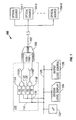
- FIG. 1 depicts an exemplary embodiment of a wavelength agile optical transponder system for testing bi-directional single-fiber WDM systems in accordance with the teachings of the present invention
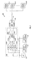
- FIG. 2 depicts another exemplary embodiment of a wavelength agile optical transponder system for testing bi-directional single-fiber WDM systems in accordance with the teachings of the present invention.
- FIG. 3 is a flow chart of the steps involved in an exemplary path monitoring method using the wavelength agile optical transponder system of the present invention.
- FIG. 1 depicted therein is an exemplary embodiment of a wavelength agile optical transponder system 100 for testing a bi-directional, single-fiber optical link 102 in accordance with the teachings of the present invention.
- a WDM coupler 106 is coupled to the optical link 102 for multiplexing and de-multiplexing optical signals of multiple wavelengths operable in different transmission bands, e.g., 1310 nm and 1550 nm bands.
- One or more optical sources operable to generate optical signals at different wavelengths are coupled to the optical link as an incident signal source.
- these optical sources may be tunable in some exemplary embodiments.
- a single tunable optical source may be provided instead as the incident signal source.
- the sources are also preferably capable of operating at various optical transmission rates such as, e.g., Optical Carrier (OC)-3, OC-12, OC-48 rates.
- the WDM coupler 106 couples to a first optical path 108A operable at a first wavelength (e.g., operable at about 1310 nm) and a second optical path 108B operable at a second wavelength (e..g, operable at about 1550 nm) for multiplexing and de-multiplexing the optical signals on to and from the single-fiber optical link 102.
- An optical cross-connect portion 120 is advantageously provided for facilitating an optical loop-back path for the incident signals in order to effectuate path integrity monitoring.
- a first optical power splitter 110A disposed in the cross-connect portion 120 is coupled to the first optical path 108A for providing receive and transmit ports to which a receiver-transmitter pair operable at the first wavelength are coupled.
- a second optical power splitter 110B is provided in the optical cross-connect portion 120 for coupling with the second optical path 108B in order to facilitate the another set of receive and transmit ports. Accordingly, receiver 112A and transmitter 114A operable with the 1310 nm band and receiver 112B and transmitter 114B operable with the 1550 nm band are exemplified in the optical cross-connect portion 120 of the optical transponder system 100.
- Optical loop-back functionality is effectuated by providing the incident signal received by a particular receiver at one wavelength to a transmitter of different wavelength by means of cross-connect mapping.
- a control entity 122 implemented as a microprocessor/microcontroller or suitable programmable logic and the like is provided for controlling optical signal processing, such as wavelength translation, shaping, grooming, power adjustment, etc., with respect to the received incident optical signals in conjunction with the provision of such signals to the cross-connected transmitters.
- Signal path 116 of the cross-connect is operable to provide a pathway for delivering the received optical signals at 1310 nm to the transmitter 114B under the control of the microprocessor 122.
- signal path 118 is operable to provide a pathway for delivering the received optical signals at 1550 nm to the transmitter 114A also under the control of the microprocessor 122.
- Additional functionality of the optical transponder system includes, by way of example, monitoring and displaying receive signal power levels, selectable control of transmitter output levels, displaying wavelength ranges of the incident signal, etc.
- a suitable bus 125 is provided for interconnecting the various opto-electronic components, e.g., display 124 and output level control 126.
- one or more 3 dB power splitters are used for providing access ports for the receivers and transmitters disposed in the optical cross-connect arrangement in accordance herewith.
- Wavelength translation for the appropriate channel pair is maintained under the control entity 122 which monitors the activity of the receivers and subsequently enables the appropriate transmitter when its complementary wavelength receiver has detected a valid signal.
- the path integrity of the optical link 102 is monitored by evaluating the incident and reflected signals via appropriate means.
- FIG. 2 depicted therein is another exemplary embodiment of a wavelength agile optical transponder system 200 for testing bi-directional, single-fiber WDM systems in accordance with the teachings of the present invention.
- the transponder system 200 is similar in many ways to the transponder system embodiment 100 described in detail hereinabove. Accordingly, only some of the salient features of the transponder system 200 are set forth hereinbelow.
- An optical cross-connect configuration 202 coupled to the embedded WDM coupler 106 includes a wavelength cross-mapping scheme 206 wherein multi-wavelength pathways 203A and 203B are cross-mapped to carry both wavelengths operable with the WDM coupler.
- Each multi-wavelength pathway is operable either in receive mode or in transmit mode and is coupled to a suitable wavelength separator/coupler for effectuating multiple receive or transmit ports. Accordingly, the receive and transmit planes are separated between a bank of receivers and transmitters which are cross-connected for effectuating the loop-back functionality.
- pathway 203 is operable as the receive path and wavelength separator/coupler 204A is coupled thereto for facilitating two receiver ports.
- Receiver 208A is provided to be operable at one wavelength (e.g., in the 1310 band) and receiver 208B is operable at another wavelength (e.g., in the 1550 band).
- pathway 203B is provided as the transmit path and wavelength separator/coupler 204B is coupled thereto for facilitating two transmitter ports.
- Transmitter 210A is operable at about 1310 nm and transmitter 210B is operable at about 1550 nm.
- Cross-connect pathways for optical loop-back functionality are effectuated by way of signal paths 212 and 214 under the control of the control entity 122 in a manner similar to the cross-connect pathways provided in the transponder embodiment 100 described hereinabove with respect to FIG. 1.
- the wavelength cross-mapping scheme 206 may be effectuated by mens of various known optical devices such as, e.g., circulators, filter, splitters, etc., operating to direct radiation at a specific wavelength to a designated path.
- Paths 216A and 218A are operable in the 1310 band as receive and transmit paths, respectively.
- paths 216B and 218B are provided as receive and transmit'paths, respectively, in the 1550 band.
- FIG. 3 is a flow chart of the steps involved in an exemplary method for testing an optical link formed of a single fiber using the wavelength agile optical transponder system of the present invention.
- the optical signal is propagated on the link via a suitable optical channel to a WDM coupler disposed on the optical link (step 304).
- the WDM coupler de-multiplexes the incident signal, whereby a receiver disposed in an optical cross-connect arrangement receives the signal for further processing (step 306).
- Wavelength translation is performed with respect to the received signal, preferably under the control of a suitable control entity (step 308).
- the optical signal with translated wavelength is provided to a complementary transmitter operating at a second wavelength (step 310) which effectuates a loop-back on the optical link.
- Path integrity of the link with respect to the radiation having the operating wavelengths is tested by monitoring signal power levels, strength and other parameters (step 312).
- Other functions may also be provided such as, e.g., monitoring and displaying receive power level, transponder input wavelength, selectable control of transmitter output levels, indicating wavelength range of the incident signal, etc.
- the present invention provides an innovative optical transponder solution that advantageously overcomes the shortcomings and deficiencies of the conventional techniques for testing WDM-based optical links.
- embedded wavelength de-multiplexor to direct radiation input to an appropriate receiver which, through intelligent supervision, enables a complementary transmitter for wavelength translation, the need for multiple transponders (each operating a predetermined wavelength) is obviated.
- the present solution allows an operator to test a single bi-directional optical link with a single test device without having to know the wavelength of the incident signal and/or direction of transmission. Automatic rate adaption to accommodate multiple carrier transmission rates is also advantageously provided.
Landscapes
- Engineering & Computer Science (AREA)
- Computer Networks & Wireless Communication (AREA)
- Signal Processing (AREA)
- Optical Communication System (AREA)
Applications Claiming Priority (2)
| Application Number | Priority Date | Filing Date | Title |
|---|---|---|---|
| US737361 | 2000-12-14 | ||
| US09/737,361 US6868233B2 (en) | 2000-12-14 | 2000-12-14 | Wavelength agile optical transponder for bi-directional, single fiber WDM system testing |
Publications (3)
| Publication Number | Publication Date |
|---|---|
| EP1215836A2 true EP1215836A2 (fr) | 2002-06-19 |
| EP1215836A3 EP1215836A3 (fr) | 2005-08-31 |
| EP1215836B1 EP1215836B1 (fr) | 2008-01-23 |
Family
ID=24963618
Family Applications (1)
| Application Number | Title | Priority Date | Filing Date |
|---|---|---|---|
| EP01129333A Expired - Lifetime EP1215836B1 (fr) | 2000-12-14 | 2001-12-14 | Transpondeur optique agile en fréquence pour tester un système à multiplexage en longueurs d'onde bidirectionnel par une seule fibre |
Country Status (4)
| Country | Link |
|---|---|
| US (1) | US6868233B2 (fr) |
| EP (1) | EP1215836B1 (fr) |
| CN (1) | CN1225095C (fr) |
| DE (1) | DE60132547D1 (fr) |
Cited By (1)
| Publication number | Priority date | Publication date | Assignee | Title |
|---|---|---|---|---|
| WO2010148960A1 (fr) * | 2009-06-23 | 2010-12-29 | 华为海洋网络有限公司 | Procede, repeteur et systeme de cable sous-marin pour controler le statut de lignes de fibres |
Families Citing this family (17)
| Publication number | Priority date | Publication date | Assignee | Title |
|---|---|---|---|---|
| US7394980B1 (en) * | 2001-01-11 | 2008-07-01 | Sprint Communications Company L.P. | Systems and methods for testing a circuit in a communication network |
| EP1271825A1 (fr) * | 2001-06-25 | 2003-01-02 | Lucent Technologies Inc. | Procédé et système pour le transport d'information optique multiplexé |
| US7561798B2 (en) * | 2003-03-07 | 2009-07-14 | Verizon Services Corp. | Testing a fiber link in a communication system without interrupting service |
| EP1649310A4 (fr) * | 2003-07-18 | 2009-04-08 | Network Integrity Systems Inc | Systeme de detection de l'intrusion d'une fibre optique multimode |
| US20050175344A1 (en) * | 2004-02-06 | 2005-08-11 | Utstarcom, Inc. | System and apparatus for a carrier class WDM PON accommodating multiple services or protocols |
| US7102517B2 (en) * | 2004-08-20 | 2006-09-05 | International Business Machines Corporation | Test fixture for evaluating RF identification system and related methods |
| US20070003283A1 (en) * | 2005-06-29 | 2007-01-04 | At&T Corp. | Dynamic allocation of bandwidth in a bidirectional optical transmission system |
| US7574136B1 (en) * | 2005-12-29 | 2009-08-11 | At&T Intellectual Property Ii, Lp | Wavelength real time display on the equipment for WDM optical networking systems with wavelength tunable capability |
| US7715678B2 (en) * | 2006-02-10 | 2010-05-11 | 3M Innovative Properties Company | Optical fiber loopback test system and method |
| US7739561B2 (en) * | 2006-07-14 | 2010-06-15 | At&T Intellectual Property 1, L.P. | Method and apparatus for monitoring an optical network signal |
| US9037746B2 (en) * | 2007-05-11 | 2015-05-19 | Verizon Patent And Licensing Inc. | Pseudowire circuit emulation |
| CN101170374B (zh) * | 2007-11-15 | 2011-08-24 | 中兴通讯股份有限公司 | 实现光同步数字传输业务环回功能的方法 |
| CN102318244A (zh) * | 2008-06-30 | 2012-01-11 | 爱立信电话股份有限公司 | 光装置 |
| WO2010095705A1 (fr) * | 2009-02-19 | 2010-08-26 | 日本電気株式会社 | Procédé de surveillance de chemin de communication et appareil de transmission |
| CN101908923B (zh) * | 2009-06-04 | 2013-08-07 | 中兴通讯股份有限公司 | 一种整机自检测系统及方法 |
| US9197352B2 (en) * | 2013-03-11 | 2015-11-24 | Google Inc. | Increasing the capacity of a WDM-PON with wavelength reuse |
| CN106656319B (zh) * | 2016-12-31 | 2019-01-22 | 瑞斯康达科技发展股份有限公司 | 一种otn业务测试方法、终端及系统 |
Family Cites Families (15)
| Publication number | Priority date | Publication date | Assignee | Title |
|---|---|---|---|---|
| JPS62213327A (ja) * | 1986-03-13 | 1987-09-19 | Fujitsu Ltd | 光波長多重伝送装置 |
| DE3713340A1 (de) * | 1987-04-21 | 1988-11-10 | Deutsche Bundespost | Verfahren zur optischen nachrichtenuebertragung |
| US4994675A (en) * | 1989-04-28 | 1991-02-19 | Rebo Research, Inc. | Method and apparatus for checking continuity of optic transmission |
| WO1992011709A1 (fr) * | 1990-12-18 | 1992-07-09 | Aster Corporation | Dispositif de commande et de surveillance de communication optique |
| DE4109683A1 (de) * | 1991-03-23 | 1992-09-24 | Standard Elektrik Lorenz Ag | System fuer optische signaluebertragung, insbesondere optisches kabelfernsehsystem, mit ueberwachungs- und dienstkanaleinrichtung |
| JPH0787021A (ja) * | 1993-09-16 | 1995-03-31 | Fujitsu Ltd | 光ファイバ通信の障害検出方法および装置 |
| JPH07261053A (ja) * | 1994-03-18 | 1995-10-13 | Fujitsu Ltd | 光合分波モジュール |
| US5680234A (en) * | 1994-10-20 | 1997-10-21 | Lucent Technologies Inc. | Passive optical network with bi-directional optical spectral slicing and loop-back |
| US5907417A (en) * | 1994-12-30 | 1999-05-25 | Lucent Technologies Inc. | Passive optical network with diagnostic loop-back |
| US5864413A (en) * | 1996-02-23 | 1999-01-26 | Lucent Technologies, Inc. | Passive optical network for dense WDM downstream data transmission and upstream data transmission |
| US5712936A (en) * | 1996-06-27 | 1998-01-27 | Mci Communications Corporation | Hybrid bi-directional three color wave division multiplexer and method using same |
| US5969836A (en) | 1997-12-12 | 1999-10-19 | Alcatel Usa Sourcing, L.P. | Method and apparatus for simultaneous transmission of digital telephony and analog video over a single optic fiber using wave division multiplexing |
| US20020015200A1 (en) * | 1998-02-05 | 2002-02-07 | Mark R. Jennings | System and method for monitoring and characterizing optical links |
| US6480648B1 (en) * | 1999-02-25 | 2002-11-12 | Lightchip, Inc. | Technique for detecting the status of WDM optical signals |
| US6317535B1 (en) * | 1999-08-24 | 2001-11-13 | Lucent Technologies Inc. | System and method for testing optical fibers that lead between a telecommunications provider and a customer's premises |
-
2000
- 2000-12-14 US US09/737,361 patent/US6868233B2/en not_active Expired - Lifetime
-
2001
- 2001-12-14 EP EP01129333A patent/EP1215836B1/fr not_active Expired - Lifetime
- 2001-12-14 CN CN01145772.4A patent/CN1225095C/zh not_active Expired - Fee Related
- 2001-12-14 DE DE60132547T patent/DE60132547D1/de not_active Expired - Lifetime
Cited By (2)
| Publication number | Priority date | Publication date | Assignee | Title |
|---|---|---|---|---|
| WO2010148960A1 (fr) * | 2009-06-23 | 2010-12-29 | 华为海洋网络有限公司 | Procede, repeteur et systeme de cable sous-marin pour controler le statut de lignes de fibres |
| US8676053B2 (en) | 2009-06-23 | 2014-03-18 | Huawei Marine Networks Co., Ltd. | Method for monitoring fiber line state, repeater, submarine cable system |
Also Published As
| Publication number | Publication date |
|---|---|
| US6868233B2 (en) | 2005-03-15 |
| DE60132547D1 (de) | 2008-03-13 |
| CN1225095C (zh) | 2005-10-26 |
| CN1366393A (zh) | 2002-08-28 |
| US20030035615A1 (en) | 2003-02-20 |
| EP1215836B1 (fr) | 2008-01-23 |
| EP1215836A3 (fr) | 2005-08-31 |
Similar Documents
| Publication | Publication Date | Title |
|---|---|---|
| CN102106103B (zh) | 光网络 | |
| US6868233B2 (en) | Wavelength agile optical transponder for bi-directional, single fiber WDM system testing | |
| AU2003200193B2 (en) | WDM optical network with passive pass-through at each node | |
| KR101390043B1 (ko) | Wdm-pon을 이용한 개방형 액세스 서비스 모델 | |
| US6567579B2 (en) | Multi-channel, multi-mode redundant optical local loop having a bus topology | |
| US6323975B1 (en) | Optical add/drop device | |
| WO2007146109A1 (fr) | Multiplexeur/démultiplexeur bidirectionnel à insertion/extraction réglable pour systèmes de transmission optique | |
| CA2412276C (fr) | Reseau optique wdm avec filtrage passif a chaque noeud | |
| US6628440B1 (en) | System for diverting an optical component signal from a multiplexed optical signal |
Legal Events
| Date | Code | Title | Description |
|---|---|---|---|
| PUAI | Public reference made under article 153(3) epc to a published international application that has entered the european phase |
Free format text: ORIGINAL CODE: 0009012 |
|
| AK | Designated contracting states |
Kind code of ref document: A2 Designated state(s): AT BE CH CY DE DK ES FI FR GB GR IE IT LI LU MC NL PT SE TR |
|
| AX | Request for extension of the european patent |
Free format text: AL;LT;LV;MK;RO;SI |
|
| PUAL | Search report despatched |
Free format text: ORIGINAL CODE: 0009013 |
|
| AK | Designated contracting states |
Kind code of ref document: A3 Designated state(s): AT BE CH CY DE DK ES FI FR GB GR IE IT LI LU MC NL PT SE TR |
|
| AX | Request for extension of the european patent |
Extension state: AL LT LV MK RO SI |
|
| 17P | Request for examination filed |
Effective date: 20060208 |
|
| AKX | Designation fees paid |
Designated state(s): DE FR GB IT |
|
| 17Q | First examination report despatched |
Effective date: 20060308 |
|
| GRAP | Despatch of communication of intention to grant a patent |
Free format text: ORIGINAL CODE: EPIDOSNIGR1 |
|
| GRAS | Grant fee paid |
Free format text: ORIGINAL CODE: EPIDOSNIGR3 |
|
| GRAA | (expected) grant |
Free format text: ORIGINAL CODE: 0009210 |
|
| AK | Designated contracting states |
Kind code of ref document: B1 Designated state(s): DE FR GB IT |
|
| REG | Reference to a national code |
Ref country code: GB Ref legal event code: FG4D |
|
| RIN1 | Information on inventor provided before grant (corrected) |
Inventor name: FOLTZER, LAWRENCE E. |
|
| REF | Corresponds to: |
Ref document number: 60132547 Country of ref document: DE Date of ref document: 20080313 Kind code of ref document: P |
|
| EN | Fr: translation not filed | ||
| PLBE | No opposition filed within time limit |
Free format text: ORIGINAL CODE: 0009261 |
|
| STAA | Information on the status of an ep patent application or granted ep patent |
Free format text: STATUS: NO OPPOSITION FILED WITHIN TIME LIMIT |
|
| 26N | No opposition filed |
Effective date: 20081024 |
|
| PG25 | Lapsed in a contracting state [announced via postgrant information from national office to epo] |
Ref country code: DE Free format text: LAPSE BECAUSE OF FAILURE TO SUBMIT A TRANSLATION OF THE DESCRIPTION OR TO PAY THE FEE WITHIN THE PRESCRIBED TIME-LIMIT Effective date: 20080424 |
|
| PG25 | Lapsed in a contracting state [announced via postgrant information from national office to epo] |
Ref country code: FR Free format text: LAPSE BECAUSE OF FAILURE TO SUBMIT A TRANSLATION OF THE DESCRIPTION OR TO PAY THE FEE WITHIN THE PRESCRIBED TIME-LIMIT Effective date: 20081114 |
|
| PGFP | Annual fee paid to national office [announced via postgrant information from national office to epo] |
Ref country code: GB Payment date: 20081216 Year of fee payment: 8 |
|
| PG25 | Lapsed in a contracting state [announced via postgrant information from national office to epo] |
Ref country code: IT Free format text: LAPSE BECAUSE OF FAILURE TO SUBMIT A TRANSLATION OF THE DESCRIPTION OR TO PAY THE FEE WITHIN THE PRESCRIBED TIME-LIMIT Effective date: 20080123 |
|
| GBPC | Gb: european patent ceased through non-payment of renewal fee |
Effective date: 20091214 |
|
| PG25 | Lapsed in a contracting state [announced via postgrant information from national office to epo] |
Ref country code: GB Free format text: LAPSE BECAUSE OF NON-PAYMENT OF DUE FEES Effective date: 20091214 |