EP1215869A2 - Verfahren und Anordnung zum Betrieb einer aus mehreren Teilnehmern bestehenden Teamkonfiguration - Google Patents
Verfahren und Anordnung zum Betrieb einer aus mehreren Teilnehmern bestehenden Teamkonfiguration Download PDFInfo
- Publication number
- EP1215869A2 EP1215869A2 EP01125554A EP01125554A EP1215869A2 EP 1215869 A2 EP1215869 A2 EP 1215869A2 EP 01125554 A EP01125554 A EP 01125554A EP 01125554 A EP01125554 A EP 01125554A EP 1215869 A2 EP1215869 A2 EP 1215869A2
- Authority
- EP
- European Patent Office
- Prior art keywords
- team
- call
- telecommunication
- subscriber
- signaling
- Prior art date
- Legal status (The legal status is an assumption and is not a legal conclusion. Google has not performed a legal analysis and makes no representation as to the accuracy of the status listed.)
- Withdrawn
Links
Images



Classifications
-
- H—ELECTRICITY
- H04—ELECTRIC COMMUNICATION TECHNIQUE
- H04M—TELEPHONIC COMMUNICATION
- H04M7/00—Arrangements for interconnection between switching centres
- H04M7/009—Arrangements for interconnection between switching centres in systems involving PBX or KTS networks
-
- H—ELECTRICITY
- H04—ELECTRIC COMMUNICATION TECHNIQUE
- H04M—TELEPHONIC COMMUNICATION
- H04M2203/00—Aspects of automatic or semi-automatic exchanges
- H04M2203/20—Aspects of automatic or semi-automatic exchanges related to features of supplementary services
- H04M2203/2044—Group features, e.g. closed user group
Definitions
- the invention relates to a method for operating a team configuration within an array of telecommunications facilities - e.g. Telecommunication systems or - server - according to the preamble of claim 1 and a corresponding Arrangement.
- FIG. 1 A corresponding configuration is shown schematically in FIG. 1 shown. This figure is due to its lettering self-explanatory and therefore requires no further explanation.
- the invention has for its object an improved Processes of the generic type and a corresponding one Specify an arrangement, in particular an improved immunity to interference have a lower signaling volume connected and more easily scalable.
- This task is regarding its procedural aspect by a method having the features of claim 1 and in terms of their device aspect through an arrangement solved with the features of claim 14.
- Fig. 2 The concept of an "imaginary team participant" is shown in Fig. 2 shown.
- a subscriber with the number 4712 is on the Telecommunications system PBX 2 (home) physically connected and thus in the team control of this telecommunications system a real team participant while in the Team controls of the telecommunications systems TK-System 1 and PBX 3 exists as an imaginary team member.
- the decentralized approach of the invention results increased reliability of the overall solution, i.e. the Failure of a telecommunication system or the connection between two telecommunication systems does not lead to loss the team functionality of the remaining telecommunications systems of the network, but only to the failure of the team functionality regarding the team participants in the failed segment of the network.
- the invention enables due to its good scalability the realization of teams with a large number of participants in a team and a large total number of team participants all in all.
- the invention enables the signaling to be minimized between the telecommunication systems and so needs one lower transmission bandwidth between the telecommunications systems than other solutions.
- the solution thus enables also a cost saving in cases where the telecommunications equipment are separated and leased lines for the connection of the individual telecommunication systems with each other are needed.
- the signaling required for the invention between the telecommunications systems regardless of the connection used between the telecommunications systems and can be made using various, even unsecured, connections and logs are made.
- the solution described in the invention recognizes independently the loss of signaling related message elements or the failure of a partner system and, managed by Detect such an error independently all affected Subscriber signaling back.
- the invention is also characterized in that Inconsistencies in the team configurations of the different Telecommunication systems within the telecommunication network be recognized independently and serious errors like this can be avoided.
- the invention is characterized in that the additional effort compared to a team solution on a single telecommunication system is low.
- each participant one real instance and n-1 imaginary instances or shadow instances assigned.
- a major advantage of the approach chosen with the invention is that the real instances and the imaginary Instances except for the aforementioned lack of the associated Process instances are identical in the imaginary instances.
- the logical address is a unique index for addressing a subscriber within a telecommunications system (a phone number is only a unique index with a uniform phone number plan, in principle closed subscriber groups are also used and it is possible to use a phone number multiple times within different closed subscriber groups) , A logical address is a unique index only within a telecommunication system and does not apply to all systems.
- Each participant has their own instance data, their current status, its configuration and its subscriber-specific Include data. This data is partial also secured and then stand even after a failure of the Telecommunications system available again.
- the part of a telecommunications system that, among other things, For the configuration of the telecommunications system is responsible.
- the part of the telecommunications system that is responsible for the control of system terminals.
- the team control on which the invention is based is implemented in this DHSYM.
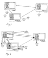
- FIG. 3 shows a distributed team configuration of 5 participants. Two team participants are physically connected to the PBX 1 and the PBX 3. A team member is physically connected to the PBX 2. Accordingly, the individual PBXs have different RTT and ITT instances (see Table 1). telephone number PBX 1 PBX 2 PBX 3 4710 RTT ITT ITT 4711 RTT ITT ITT 4712 ITT RTT ITT 4713 ITT ITT RTT 4723 ITT ITT RTT
- a first step 1) the incoming call of the RTT instance of subscriber 4710 delivered to PBX 1.
- a second step 2) the incoming call is the subscriber 4710 delivered, i.e. the doorbell rings with the number 4710.
- the RTT instance of the participant 4710 states that this subscriber has a call distribution activated and also by team partners on the PBX 3 is monitored.
- the RTT instance of subscriber 4710 sends then a message with the parameters of the call to the PBX 3, regardless of how many participants on the PBX 3 monitor subscriber 4710 and regardless of whether these participants activate call pickup for team calls have or not.
- PBXs 2 and 3 are not notified of this call. Only when the subscriber 4710 the call distribution activated and in cases where the call is still pending, PBX systems 2 and 3 are notified. The parameters are in the ITT instance of subscriber 4710 of the incoming call and, if necessary, to the Team participants distributed [see following steps 5) and 6)].
- a fifth step 5 the RTT instance of the participant 4710 notes that the participant 4710 also from team partners is monitored on the PBX 2, and also sends a message to the PBX 2 [analogous to step 3)].
- the ITT instance of subscriber 4710 was in incoming call signaled. In a sixth step 6) this call now distributed to the corresponding team partners. Based on Data of the ITT instance of subscriber 4710 on the PBX 3, it is determined that this is being monitored by subscriber 4723 and via the RTT instance of subscriber 4723 it is determined that subscriber 4723 is answering the call activated. Now team member 4723 will be the next Call signaled as if it were the team call for you Team partner of your own PBX 3.
- a seventh step the participant becomes analogous to step 6) 4713 the team call signals.
- step 8 the participant becomes analogous to step 6) 4712 on the PBX 2 the team call is signaled.
- a team member e.g. the subscriber 4713
- a call for a team partner e.g. 4710
- the team member can accept this call for accept his team partner. This is done via a targeted Call inquiry, i.e. subscriber 4713 signals the PBX 1 that he wants to accept the call for subscriber 4710 and the PBX 1 transfers this call to subscriber 4713 on the PBX 3.
- the PBX now receives an incentive from the previous one failed partner system, the signaling of Call status again, i.e. the cross-system functionality is now available again. For performance reasons at the "first contact” or at the "reunion” of the networked PBXs no refresh of all switching states Team participants.
- Fig. 5 it is assumed that the connections of the PBX 1 to PBX systems 2 and 3 are severed. The outside line the PBX 1 has been preserved and Subscriber 4710 will continue to be called. The team partner 4711 The call is still signaled on the PBX 1 and the call can also be accepted.
- the cross-network teams are configured by a program that runs on one of the PBXs or on one external computer is started. This program is running independent of the actual team control and is used for does not need the actual operation of the team, but rather only for cross-network configuration.
- the team configuration is for the consistency of the data distributed teams and enables new team participants to include in a team, participants from a team delete or the specifications of which team participants which Team partners may monitor changes. This calls for this Program the current team configuration of the individual PBXs and then works with the data of the "real team participants" (RTT).
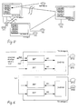
- Fig. 6 two networked PBXs are shown in simplified form.
- Team control is assigned to the DHSYM complex.
- the end devices with team functionality are provided by the DHSYM controlled.
- the DHSYM communicates via the internal Interfaces # l1 and # l2 with the components ZBT and ZVT.
- the communication that takes place via the interface # l1 the configuration of the team data is necessary.
- the Interface # l2 is the communication for cross-plant Call signaling within networked Teams is necessary.
- the DHSYM addresses via the ZVT component of your own PABX the external interface # e1 and above it the ZVT component the partner system that sends this signaling to the DHSYM passes the partner system.
- the external interfaces # e2 and # e3 serve the ZBT component u. a. for configuration of cross-plant teams.
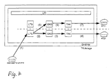
- Fig. 7 is the distribution of a call within a single system shown.
- the subscriber 4710 receives a call: (1). This call is signaled on your own device: (2) to 4). Based on the team data, the LTG component of the Participant 4710 determined that the participant 4711 the Participant 4710 actively monitors and also participant 4711 the call is signaled: (5) to (7).
- the routing processes [(1) to (7)] within the PABX 1 are identical to those of a single system.
- the LTG process of the called party 4710 now determines that this party 4710 also monitored by team partners on other telecommunications systems and the LTG process sends a message to the global UTI process (8).
- the data of the call (phone number of the caller, ...) temporarily stored in the data of the ITT instance.
- the ITT data is then used to determine which real team participants of the corresponding PABX 2 and 3 monitor the subscriber 4710. For each of these team participants it is now determined whether he activates the call pickup in the team Has.
- the UTI process now generates one for all affected RTTs Message to the RTD END process [(10), (14) and (17)].
- This message is sent as the sender of the LTG process Participant 4710 simulated, i.e. for the END process and the following processes [(11), (12), (15), (16), (18) and (19)] the signaling of the team call behaves analogously to one Single asset.
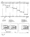
- Fig. 9 this is cross-system routing of a team call shown as a communication diagram.
- the ZVT component sends the S_DT_KLE message to the LTG process of the participant 4710 and signals him that he is called. Signaled with the message LTG_END_TT_RUFT the participant's LTG process 4710 the participant's END process 4711 the team reputation. With the message LTG_UTI_SYN_TT_RUFT becomes the cross-plant routing initiated. The UTI process now sends the message DG_SYM / UTI_SYN_TT_RUFT to the ZVT component. It routes it Datagram then to the PBX 2.
- the ZVT component then sends the message on the PBX 2 DG_SYM / UTI_SYN_TT_RUFT forward to the UTI process.
- the UTI process then determines the affected instances of the team partners and sends the message LTG_END_TT_RUFT to the participant 4712th
- a participant's team data were added parameters extended for cross-system routing; so e.g. the plant number of a TT.
- FIG. 10 shows a schematic illustration for explanation the storage organization in connection with the implementation of a team reputation.
- the team participant indices (tfi) of the different telecommunications systems can assume different values for the same subscriber on the different telecommunications systems, ie the scope of validity of a tti is limited to one system.
- Missing message detection is based on simple Numbering of every message from the team control one PBX is sent to another PBX.
- the team control each individual PBX saves when you receive one Message from a partner system the number of the last received message in a list between (an entry for each partner system). Now the next message from received by the partner system, the cached Number compared with the number of the new message. Is the Number of the new message one more than that of the cached, so no message has been lost and the processing of the call signaling can take place normally. Is the delta between the cached number with the number of the new message not equal to one, so lies an error case. It is now all new messages discarded by the corresponding partner system until all signaling relating to this system is managed back have been.
- the message number When receiving a message from a partner system, the same applies the message number also includes a timestamp in one global list (one entry for each partner system) saved. This list is now cyclical (e.g. once per minute) processed for all partner plants with which active relationships exist, i.e. it becomes the current system time with the saved timestamp of receipt of the last message compared.
- This mechanism ensures that after a finite Time after the connection to a partner system fails all calls are managed back, i.e. a team call rings not forever.
Landscapes
- Engineering & Computer Science (AREA)
- Signal Processing (AREA)
- Telephonic Communication Services (AREA)
- Exchange Systems With Centralized Control (AREA)
Abstract
Description
- Ausfall der Teamfunktionalität in allen abgesetzten Telekommunikationsanlagen bei einem Ausfall der Masteranlage oder bei einem Ausfall der Verbindung zur Masteranlage.
- Beim Ausfall der Masteranlage sind die abgesetzten Team-Teilnehmer nicht mehr erreichbar, können aber selber noch telefonieren.
- Aufgrund der Steuerung der Teamfunktionalität ausgehend von einer zentralen Masteranlage besteht auf der Masteranlage ein erhöhter Performancebedarf.
- Aufgrund der Steuerung jedes einzelnen Team-Teilnehmers ausgehend von einer Masteranlage entsteht ein erhöhtes Signalisierungsaufkommen, da jeder Team-Teilnehmer auf einer abgesetzten Anlage einzeln gesteuert werden muß (z.B. Signalisierung eines Team-Rufes über eine LED einschalten).
- Die beiden obengenannten Punkte bewirken eine schlechte Skalierbarkeit eines derartigen Lösungsansatzes, d.h. große verteilte Teams sind nur schwer realisierbar, da der Signalisierungsaufwand zwischen den abgesetzten Telekommunikationsanlagen und der Masteranlage linear mit der Anzahl der abgesetzten Team-Teilnehmer steigt.
- die demselben Rufnummernplan angehören,
- die sich auf verschiedenen vernetzten Telekommunikationsanlagen befinden können,
- deren Rufe innerhalb der Gruppe in Abhängigkeit von der Konfiguration signalisiert werden;
- der Teamnummer zugeordnet ist.
- die kommenden Rufe dieses TT können anderen Teilnehmern im selben Team signalisiert werden;
- diesem TT können die kommenden Rufe anderer Teilnehmer im selben Team signalisiert werden;
- der TT kann die Rufe anderer TT übernehmen;
- die Rufe dieses TT können von anderen TT übernommen werden;
- ein TT kann einem anderen TT einen Ruf zuteilen;
- ein TT kann die Anrufverteilung seiner Rufe ein- oder ausschalten;
- ein TT kann die Anrufübernahme für die ihm signalisierten Rufe seiner Team-Partner ein- oder ausschalten.
- ein RTT ist sowohl auf Einzelanlagen als auch bei vernetzten Telekommunikationsanlagen möglich;
- bei einem RTT im Anlagenverbund wird auch vom Home des TT gesprochen;
- ein RTT kann teilnehmerindividuelle Daten sichern und so z.B. speichern, an welcher Tastenposition ein anderer Team-Partner überwacht wird;
- ein RTT verfügt typischerweise über eine physikalische Entsprechung (d.h. ein angeschlossenes Kommunikationsendgerät); ein RTT kann aber auch ein "virtueller Team-Teilnehmer sein.
- die Rufnummer dieses Teilnehmers ist im gleichen Wählbaum wie die seiner Team-Partner und verweist auf die Anlassung zu einer anderen Anlage;
- zu einem ITT gehört immer ein RTT;
- bei n-vernetzten Telekommunikationsanlagen gehören zu einem RTT (n-1) ITT's;
- ein ITT hat keine Instanzdaten für ein Kommunikationsendgerät, sondern nur Team-Daten;
- ein ITT kann keine teilnehmerindividuellen Daten sichern;
- die Daten eines ITT's werden u.a. aus den Team-Daten der RTT's der Anlage rekonstruiert;
- ein ITT verteilt die Rufe des zugehörigen RTT einer Partneranlage.
- der VTT kann selbst keinen Ruf annehmen oder gehend eine Leitung belegen;
- der VTT wird z.B. für die Anrufverteilung im Team benutzt;
- ein VTT ist ein Hilfskonstrukt in einer Teamkonfiguration, das, unabhängig von der Vernetzungs-Problematik, dazu genutzt wird, die Anzahl der von extern erreichbaren Rufnummern im Team zu erhöhen, ohne die Anzahl der tatsächlichen Teilnehmer zu erhöhen (So kann ein Teilnehmer z.B. unter 3 verschiedenen Rufnummern erreichbar sein).
- TK's sind entweder vom Konfigurator fest vorgegeben oder können entsprechend der Vorgaben des Konfigurators frei programmiert werden;
- TK's werden durch eine virtuelle Tastenposition der Rufnummer des Team-Partners, die Signalisierungsart und den zugehörigen Rufrythmus beschrieben.
Eine logische Adresse ist nur innerhalb einer Telekommunikationsanlage ein eineindeutiger Index und gilt nicht anlagen-übergreifend.
Diese werden auch als Instanz bzw. Inkarnation dieses Teilnehmers bezeichnet.
- die Team-Daten sind an die Rufnummer und die Teamnummer eines Team-Teilnehmers gebunden;
- über die Instanzdaten eines RTT ist mit Hilfe des Team-Teilnehmer Index (M) ein Zugriff auf die eigenen Team-Daten und die Team-Daten der Team Partner möglich;
- ein zentraler Prozeß (UTI) kann auf die Team-Daten aller Team-Teilnehmer zugreifen;
- ITT's verfügen nur über Team-Daten (es gibt keine Instanz und keine Instanzdaten (END-,LTG und TAK-Prozeß)für einen ITT).
In diesem DHSYM ist die der Erfindung zugrundeliegende Teamsteuerung realisiert.
- Fig. 3:
- eine schematische Darstellung einer verteilten Teamkonfiguration aus fünf Teilnehmern,
- Fig. 4:
- eine Darstellung zur Verteilung eines kommenden Rufes innerhalb des verteilten Teams nach Fig. 3,
- Fig. 5:
- eine beispielhafte Darstellung zur Erläuterung der Fehlererkennung und -behandlung bei einer Teamkonfiguration nach Fig. 3,
- Fig. 6:
- eine schematische Darstellung zum Aufbau von Telekommunikationsanlagen, aus denen eine Anordnung gemäß einem Ausführungsbeispiel der Erfindung gebildet ist,
- Fig. 7:
- eine schematische Darstellung zur Verteilung eines Team-Rufes in einer Einzelanlage gemäß einer Ausführungsform der Erfindung,
- Fig. 8:
- eine schematische Darstellung eines netzübergreifenden Routing eines Rufes gemäß einer Ausführungsform der Erfindung,
- Fig. 9:
- eine Darstellung eines anlagenübergreifenden Kommunikationsdiagramms bei einer Ausführungsform der Erfindung und
- Fig. 10:
- eine schematische Darstellung zur Erläuterung der Speicherorganisation im Zusammenhang mit der Realisierung eines Team-Rufes bei einer Ausführungsform der Erfindung.
| Rufnummer | TK-Anlage 1 | TK-Anlage 2 | TK-Anlage 3 |
| 4710 | RTT | ITT | ITT |
| 4711 | RTT | ITT | ITT |
| 4712 | ITT | RTT | ITT |
| 4713 | ITT | ITT | RTT |
| 4723 | ITT | ITT | RTT |
- Team-Teilnehmer ist belegt,
- Team-Teilnehmer ist frei,
- Ende des Rufes für den Team-Teilnehmer
- das Erkennen des Ausfalls einer Partner-TK-Anlage bzw. des Ausfalls der Routingwege zu dieser TK-Anlage,
- das Erkennen dessen, daß eine Partner-TK-Anlage neu hochgelaufen ist,
- das Erkennen von Verlusten einer oder mehrerer Nachrichten in der Kommunikation mit einer Partneranlage,
- das Erkennen von inkonsistenten Teamkonfigurationen.
- akustisch (Normalruf oder Kurzruf)
- im Display des entsprechenden Endgerätes
- an der LED der entsprechenden Team-Taste am Endgerät (blinken)
- über die Team-Taste am Endgerät
- über einen entsprechenden Menüpunkt im Display, auch wenn es die korrespondierende Team-Taste physikalisch gar nicht gibt, z.B. an einem DECT-Mobiltelefon
- über eine separate Funktionstaste
- über einen Menüpunkt
- über eine separate Funktionstaste
- über einen Menüpunkt
- der Teilnehmer 4710 wird gerufen
- der Teilnehmer 4710 ist im Team Nr.2
- die Parameter des Rufes, z.B.:
- wenn bekannt, die Rufnummer und den Namen des Rufers
- den Rufrythmus
- die Teilnehmerart des Rufers etc.
Ein Team-Teilnehmer (Ruf-Nr. 4710) auf Anlage 1 wird vom Amt (Ruf-Nr. 05251820718) gerufen. Ein weiterer Team-Teilnehmer (Ruf-Nr. 4712) im selben Team, aber auf einer anderen Anlage (Anlage 2), überwacht den Gerufenen auf einer Team-Taste (Team Key). An der LED dieser Team-Taste, über einen Kurzruf und im Display wird der kommende Ruf des Team-Partners beim Teilnehmer (4712) signalisiert.
Claims (16)
- Verfahren zum Betrieb einer aus mehreren Teilnehmern bestehenden Teamkonfiguration in einer aus einer Mehrzahl von untereinander verbundenen Telekommunikationseinrichtungen bestehenden Anordnung,
dadurch gekennzeichnet, daß
die Telekommunikationseinrichtungen gleichrangig miteinander kommunizieren, wobei für jeden Teilnehmer in jeder Telekommunikationseinrichtungen neben den zum normalen Telekommunikationsbetrieb vorgesehenen Prozeßinstanzen eine reale oder eine imaginäre Instanz eingerichtet wird. - Verfahren nach Anspruch 1,
dadurch gekennzeichnet, daß
in einer Teamkonfiguration mit n Telekommunikationseinrichtungen jedem Teilnehmer eine reale Instanz und n-1 imaginäre Instanzen zugewiesen sind. - Verfahren nach Anspruch 1 oder 2,
dadurch gekennzeichnet, daß
jede Statusänderung eines Teilnehmers nur einmal an eine Partner-Telekommunikationseinrichtung signalisiert und in dieser die Steuerung der Teamfunktionalität durch die dem Teilnehmer dort zugewiesene imaginäre Instanz ausgeführt wird. - Verfahren nach einem der vorangehenden Ansprüche,
dadurch gekennzeichnet, daß
bei Erkennung des Ausfalls einer Telekommunikationseinrichtungen bzw. eines Routingweges zu dieser Telekommunikationseinrichtungen ein anstehender Team-Ruf selbsttätig beendet wird und alle Rufstati zurückverwaltet werden. - Verfahren nach Anspruch 4,
dadurch gekennzeichnet, daß
im Ansprechen auf eine Reaktivierung der ausgefallenen Telekommunikationseinrichtung kein Wiederauffrischen der Vermittlungsstati der Teilnehmer durchgeführt wird. - Verfahren nach einem der vorangehenden Ansprüche,
dadurch gekennzeichnet, daß
die Konfigurierung der Teamkonfiguration durch ein von einer Betriebssteuerung unabhängigem Programm ausgeführt wird, welches in einer der Telekommunikationseinrichtungen oder einem extern an die Anordnung angeschlossenen Datenverarbeitungseinrichtung implementiert ist. - Verfahren nach einem der vorangehenden Ansprüche,
gekennzeichnet durch
die Realisierung folgender Teamleistungsmerkmale über die gesamte Anordnung:(1) Signalisierung von Team-Rufen,(2) Signalisierung von Besetztzuständen, insbesondere über eine optische Anzeige am entsprechenden Endgerät,(3) die Möglichkeit der Annahme eines Team-Rufes,(4) die Möglichkeit des direkten Rufes eines Teilnehmers des Teams über eine Funktionstaste,(5) die Möglichkeit der Zuteilung eines Gespräches an einen Teilnehmer des Teams über die Funktionstaste,(6) die Möglichkeit einer Aktivierung/Deaktivierung der Verteilung eigener Rufe im Team und(7) die Möglichkeit der Aktivierung/Deaktivierung einer Signalisierung anderer Team-Rufe am eigenen Endgerät. - Verfahren nach Anspruch 7,
gekennzeichnet durch
die freie Programmierbarkeit der Art der Signalisierung eines Team-Rufes über die Funktionstaste am einem jeweiligen Telekommunikations-Endgerät. - Verfahren nach Anspruch 7 oder 8,
dadurch gekennzeichnet, daß
die Signalisierung von Team-Rufen akustisch über einen Normalruf oder Kurzruf erfolgt. - Verfahren nach einem der Ansprüche 7 bis 9,
dadurch gekennzeichnet, daß
die Signalisierung von Team-Rufen optisch im Display oder an der Funktionstaste des jeweiligen Telekommunikations-Endgerätes erfolgt. - Verfahren nach einem der Ansprüche 7 bis 10,
dadurch gekennzeichnet, daß
die Annahme eines Team-Rufes, die Aktivierung/Deaktivierung der Signalisierung anderer Team-Rufe am Telekommunikations-Endgerät eines Teilnehmers und/oder die Aktivierung/Deaktivierung der Verteilung eigener Rufe im Team jeweils über eine spezielle Funktionstaste am Telekommunikations-Endgerät erfolgt. - Verfahren nach einem der Ansprüche 7 bis 10,
dadurch gekennzeichnet, daß
die Annahme eines Team-Rufes, die Aktivierung/Deaktivierung der Signalisierung anderer Team-Rufe am Telekommunikations-Endgerät eines Teilnehmers und/oder die Aktivierung/Deaktivierung der Verteilung eigener Rufe im Team jeweils über einen Menüpunkt einer, insbesondere optischen, Menüführung erfolgt. - Verfahren nach einem der vorangehenden Ansprüche,
gekennzeichnet durch
die Einbindung rein virtueller Teilnehmer mit eigener Rufnummer, aber ohne reale Instanz. - Anordnung zum Betrieb einer aus mehreren Teilnehmern bestehenden Teamkonfiguration mit einer Mehrzahl von untereinander verbundenen Telekommunikationseinrichtungen,
dadurch gekennzeichnet, daß
die Telekommunikationseinrichtungenjeweils eine der Steuerung von System-Telekommunikationsendgeräten zugeordnete Teamsteuerung,eine erste und zweite interne, direkt der Steuerung der System-Telekommunikationsendgeräte zugeordnete Schnittstelle, undeine erste und zweite externe, durch die Steuerung der System-Telekommunikationsendgeräte indirekt adressierte Schnittstelle als Konfigurations- bzw. Signalisierungsanschlüsse für eine teaminterne Signalisierung aufweisen. - Anordnung nach Anspruch 14,
dadurch gekennzeichnet, daß
die erste und zweite interne Schnittstelle die Steuerung der System-Telekommunikationsendgeräte und damit die Teamsteuerung mit einer Komponente Zentrale Betriebstechnik bzw. einer Komponente Zentrale Vermittlungstechnik verbinden. - Anordnung nach Anspruch 15,
dadurch gekennzeichnet, daß
die erste externe Schnittstelle die Komponente Zentrale Betriebstechnik mit einer entsprechenden Komponente einer anderen Telekommunikationseinrichtung oder einem Konfigurationstool und die zweite externe Schnittstelle die Komponenten Zentrale Vermittlungstechnik zweier Telekommunikationseinrichtungen miteinander verbindet.
Applications Claiming Priority (2)
| Application Number | Priority Date | Filing Date | Title |
|---|---|---|---|
| DE10061295 | 2000-12-08 | ||
| DE10061295 | 2000-12-08 |
Publications (2)
| Publication Number | Publication Date |
|---|---|
| EP1215869A2 true EP1215869A2 (de) | 2002-06-19 |
| EP1215869A3 EP1215869A3 (de) | 2003-04-02 |
Family
ID=7666419
Family Applications (1)
| Application Number | Title | Priority Date | Filing Date |
|---|---|---|---|
| EP01125554A Withdrawn EP1215869A3 (de) | 2000-12-08 | 2001-10-25 | Verfahren und Anordnung zum Betrieb einer aus mehreren Teilnehmern bestehenden Teamkonfiguration |
Country Status (2)
| Country | Link |
|---|---|
| US (1) | US20020136386A1 (de) |
| EP (1) | EP1215869A3 (de) |
Cited By (1)
| Publication number | Priority date | Publication date | Assignee | Title |
|---|---|---|---|---|
| EP2093985A1 (de) | 2008-02-21 | 2009-08-26 | Avaya GmbH & Co. KG | Verfahren zum Betreiben einer Telefonanlage mit mindestens zwei Telefonie-Endgeräte und Telefonie-Endgerät zur Durchführung des Verfahrens |
Families Citing this family (4)
| Publication number | Priority date | Publication date | Assignee | Title |
|---|---|---|---|---|
| ATE363811T1 (de) * | 2002-04-03 | 2007-06-15 | Evolium Sas | Spezifischer datenregistrierungsserver in einem bedien- und verwaltungszentrum für ein telekommunikationssystem |
| DE102004013392A1 (de) * | 2004-03-17 | 2005-10-27 | Tenovis Gmbh & Co. Kg | Verfahren zur Konfiguration und Verfahren zum Betrieb eines Telekommunikationssystems, Dispatcher-Software in einem Telekommunikationssystem sowie Telekommunikationsanlage |
| EP2083559A1 (de) * | 2008-01-23 | 2009-07-29 | Avaya GmbH & Co. KG | Verfahren zum Herstellen einer Kommunikationsverbindung zu Gruppenrufnummern und Übermittlung von Statusnachrichten an den Anrufer |
| US8249627B2 (en) * | 2009-12-21 | 2012-08-21 | Julia Olincy | “I am driving/busy” automatic response system for mobile phones |
Family Cites Families (11)
| Publication number | Priority date | Publication date | Assignee | Title |
|---|---|---|---|---|
| US5638432A (en) * | 1992-06-23 | 1997-06-10 | Siemens Aktiengesellschaft | Method of setting up telecommunication connections |
| FI97191C (fi) * | 1994-10-05 | 1996-10-25 | Nokia Telecommunications Oy | Alueellinen Centrex |
| JPH08242475A (ja) * | 1995-03-06 | 1996-09-17 | Toshiba Corp | 構内交換機の着信方法及び発信方法 |
| US5978464A (en) * | 1995-06-30 | 1999-11-02 | Siemens Information And Communications Networks, Inc. | Method for updating a local switch internal database in system having different service providers within a common numbering plan area |
| DE19640221A1 (de) * | 1996-09-30 | 1998-04-02 | Siemens Ag | Kommunikationssystem aus mindestens zwei Nebenstellenanlagen mit Teamfunktion |
| DE19640266A1 (de) * | 1996-09-30 | 1998-04-02 | Siemens Ag | Kommunikationssystem aus mindestens zwei Nebenstellenanlagen mit Teamfunktion |
| EP0876067A1 (de) * | 1997-04-30 | 1998-11-04 | Alcatel | Virtuelle Privatnetze mit gemeinsamem Bestimmungsort |
| US6047058A (en) * | 1997-09-18 | 2000-04-04 | Siemens Aktiengesellschaft | Communication system of at least two private branch exchanges having a team function |
| DE19752403C2 (de) * | 1997-11-26 | 2002-06-13 | Siemens Ag | Kommunikationssystem |
| DE19852774B4 (de) * | 1998-11-16 | 2006-05-04 | Siemens Ag | Telefonvermittlungssystem zur Eingliederung von Mobilnetzteilnehmern in eine CENTREX-Gruppe |
| DE59811062D1 (de) * | 1998-12-17 | 2004-04-29 | Siemens Ag | Verfahren zur Realisierung von Anrufübernahmegruppen in einem Kommunikationnsetz |
-
2001
- 2001-10-25 EP EP01125554A patent/EP1215869A3/de not_active Withdrawn
- 2001-12-10 US US10/015,017 patent/US20020136386A1/en not_active Abandoned
Cited By (2)
| Publication number | Priority date | Publication date | Assignee | Title |
|---|---|---|---|---|
| EP2093985A1 (de) | 2008-02-21 | 2009-08-26 | Avaya GmbH & Co. KG | Verfahren zum Betreiben einer Telefonanlage mit mindestens zwei Telefonie-Endgeräte und Telefonie-Endgerät zur Durchführung des Verfahrens |
| US8139740B2 (en) | 2008-02-21 | 2012-03-20 | Avaya Inc. | Method for operating a telephone system with at least two telephony terminals and a telephony terminal for carrying out the method |
Also Published As
| Publication number | Publication date |
|---|---|
| EP1215869A3 (de) | 2003-04-02 |
| US20020136386A1 (en) | 2002-09-26 |
Similar Documents
| Publication | Publication Date | Title |
|---|---|---|
| EP0631454B1 (de) | Verfahren zum Einrichten von virtuellen Verbindungen in Paketvermittlungsnetzen | |
| EP1014660A2 (de) | Verfahren zum Realisieren einer Sammelanschlussfunktion in einem Kommunikationsnetz nach ITU-T H.323 | |
| EP0630142A1 (de) | Verfahren zur Abspeicherung von Nachrichten in vernetzten Nachrichtenspeichereinheiten | |
| DE3727952A1 (de) | Modular strukturiertes digitales kommunikationssystem | |
| EP1215869A2 (de) | Verfahren und Anordnung zum Betrieb einer aus mehreren Teilnehmern bestehenden Teamkonfiguration | |
| EP0813330B1 (de) | Verbindungsaufbauverfahren sowie Vermittlungsstelle, Dienstrechner und Kommunikationsnetz | |
| EP1387589A1 (de) | Media Gateway zur Bereitstellung der PSTN/ISDN Dienste in Netzwerken der nächsten Generation | |
| EP0697796B1 (de) | Kommunikationsvermittlungssystem mit einem Leistungsmerkmalsystem und einem Basisvermittlungssystem | |
| DE69801237T2 (de) | Datenkommunikationssystem mit hierarchischem netzwerkmodel zur definition von logischen und physikalischen objekten | |
| DE19836560A1 (de) | Verfahren und Einrichtung zur Überprüfung der Funktionsfähigkeit einer Vermittlungsstelle | |
| DE102004055494B4 (de) | Verfahren zur Weiterleitung eines Rufes in einem der direkt kommunizierenden Kommunikationsnetzwerk und Kommunikationskomponente für ein direkt kommunizierendes Kommunikationsnetzwerk | |
| EP1424845A2 (de) | Verfahren zur Integration eines paketorientierten Netzwerks in ein Kommunikationssystem | |
| EP0535601B1 (de) | Verfahren zur Herstellung von Konferenzverbindungen in einer rechnergesteuerten Kommunikationsanlage | |
| DE60302042T2 (de) | Netzwerkwartung | |
| EP0529343B1 (de) | Verfahren zur Herstellung einer Verbindung zwischen einem an eine Kommunikationsanlage angeschlossenen Kommunikationsendegerät mit einer Mehrzahl von weiteren Geräten | |
| EP1584176B1 (de) | Verfahren und anordnung zur steuerung und/oder überwachung eines an ein kommunikations-system angeschlossenen endgerätes | |
| EP1202523A2 (de) | Vorrichtung und Verfahren zum Synchronisieren von Datenbanken in verteilten Kommunikationssystemen | |
| EP0782810B1 (de) | Verfahren und anordnung zur auflösung von leistungsmerkmal-interaktionen in einem kommunikationssystem | |
| DE102004012503B4 (de) | Kommunikationsserver und Verfahren zur Steuerung und Überwachung von Endgeräten, und Kombination aus einem Kommunikationsserver, einer Mehrzahl von Kommunikationsknoten und Endgeräten | |
| EP1163805B1 (de) | Verfahren zum übertragen von daten an mitglieder eines operatorservices | |
| EP1189461A2 (de) | Verteiltes Kommunikationssystem | |
| DE10120041B4 (de) | Verfahren zur Überwachung von Zuständen von Telekommunikationsendgeräten und Telekommunikationssystem | |
| DE60122758T2 (de) | Verteilte vermittlungsplattform und betriebsverfahren dafür | |
| DE19535545C2 (de) | Verfahren für einen Notbetrieb bei Ausfall einer automatischen Anrufverteilung in einem Kommunikationssystem | |
| EP1014634A1 (de) | Verfahren und Vorrichtung zum Aufbau von Verbindungen von einem Endgerät über ein erstes Netz zu einem Netzzugangspunkt eines zweiten Netzes |
Legal Events
| Date | Code | Title | Description |
|---|---|---|---|
| PUAI | Public reference made under article 153(3) epc to a published international application that has entered the european phase |
Free format text: ORIGINAL CODE: 0009012 |
|
| AK | Designated contracting states |
Kind code of ref document: A2 Designated state(s): AT BE CH CY DE DK ES FI FR GB GR IE IT LI LU MC NL PT SE TR |
|
| AX | Request for extension of the european patent |
Free format text: AL;LT;LV;MK;RO;SI |
|
| PUAL | Search report despatched |
Free format text: ORIGINAL CODE: 0009013 |
|
| RIC1 | Information provided on ipc code assigned before grant |
Ipc: 7H 04M 3/54 B Ipc: 7H 04M 3/46 A |
|
| AK | Designated contracting states |
Kind code of ref document: A3 Designated state(s): AT BE CH CY DE DK ES FI FR GB GR IE IT LI LU MC NL PT SE TR Designated state(s): AT BE CH CY DE DK ES FI FR GB GR IE IT LI LU MC NL PT SE TR |
|
| AX | Request for extension of the european patent |
Extension state: AL LT LV MK RO SI |
|
| 17P | Request for examination filed |
Effective date: 20030303 |
|
| 17Q | First examination report despatched |
Effective date: 20030801 |
|
| AKX | Designation fees paid |
Designated state(s): DE FR GB IT |
|
| STAA | Information on the status of an ep patent application or granted ep patent |
Free format text: STATUS: THE APPLICATION HAS BEEN WITHDRAWN |
|
| 18W | Application withdrawn |
Effective date: 20050407 |