EP1215906A2 - Auf die Wand montierte optische Steckdose zum Empfangen und Senden - Google Patents
Auf die Wand montierte optische Steckdose zum Empfangen und Senden Download PDFInfo
- Publication number
- EP1215906A2 EP1215906A2 EP01811124A EP01811124A EP1215906A2 EP 1215906 A2 EP1215906 A2 EP 1215906A2 EP 01811124 A EP01811124 A EP 01811124A EP 01811124 A EP01811124 A EP 01811124A EP 1215906 A2 EP1215906 A2 EP 1215906A2
- Authority
- EP
- European Patent Office
- Prior art keywords
- optical
- socket
- optical fibre
- signal
- fibre
- Prior art date
- Legal status (The legal status is an assumption and is not a legal conclusion. Google has not performed a legal analysis and makes no representation as to the accuracy of the status listed.)
- Withdrawn
Links
Images




Classifications
-
- H—ELECTRICITY
- H04—ELECTRIC COMMUNICATION TECHNIQUE
- H04N—PICTORIAL COMMUNICATION, e.g. TELEVISION
- H04N7/00—Television systems
- H04N7/22—Adaptations for optical transmission
-
- H—ELECTRICITY
- H01—ELECTRIC ELEMENTS
- H01R—ELECTRICALLY-CONDUCTIVE CONNECTIONS; STRUCTURAL ASSOCIATIONS OF A PLURALITY OF MUTUALLY-INSULATED ELECTRICAL CONNECTING ELEMENTS; COUPLING DEVICES; CURRENT COLLECTORS
- H01R24/00—Two-part coupling devices, or either of their cooperating parts, characterised by their overall structure
- H01R24/38—Two-part coupling devices, or either of their cooperating parts, characterised by their overall structure having concentrically or coaxially arranged contacts
- H01R24/40—Two-part coupling devices, or either of their cooperating parts, characterised by their overall structure having concentrically or coaxially arranged contacts specially adapted for high frequency
- H01R24/52—Two-part coupling devices, or either of their cooperating parts, characterised by their overall structure having concentrically or coaxially arranged contacts specially adapted for high frequency mounted in or to a panel or structure
- H01R24/525—Outlets
-
- H—ELECTRICITY
- H04—ELECTRIC COMMUNICATION TECHNIQUE
- H04N—PICTORIAL COMMUNICATION, e.g. TELEVISION
- H04N7/00—Television systems
- H04N7/10—Adaptations for transmission by electrical cable
- H04N7/102—Circuits therefor, e.g. noise reducers, equalisers, amplifiers
-
- H—ELECTRICITY
- H04—ELECTRIC COMMUNICATION TECHNIQUE
- H04N—PICTORIAL COMMUNICATION, e.g. TELEVISION
- H04N7/00—Television systems
- H04N7/10—Adaptations for transmission by electrical cable
- H04N7/106—Adaptations for transmission by electrical cable for domestic distribution
-
- H—ELECTRICITY
- H01—ELECTRIC ELEMENTS
- H01R—ELECTRICALLY-CONDUCTIVE CONNECTIONS; STRUCTURAL ASSOCIATIONS OF A PLURALITY OF MUTUALLY-INSULATED ELECTRICAL CONNECTING ELEMENTS; COUPLING DEVICES; CURRENT COLLECTORS
- H01R2103/00—Two poles
Definitions
- the present invention relates to a socket for a connection between an optical fibre telecommunications network and the equipment located in a user's home for receiving and transmitting signals. More particularly, the present invention relates to a device for receiving a television signal from an optical fibre CATV network and transferring it to the television set via a coaxial cable, and for transferring signals of the electrical or optical type, sent from equipment in a subscriber's home, to the optical fibre network.
- the present invention is particularly suited to CATV distribution systems in which AM (amplitude modulated) signals and those of the DOCSIS type are generated or transmitted.
- the configuration of a television signal network comprises an optical fibre portion and a coaxial cable portion leading to the customer.
- the liberalization in the field of telecommunications in recent years has enabled the owners of these networks to offer new services in addition to the conventional provision of radio and television programmes.
- This has been made possible by the transmission of data by means of suitable modems with radio-frequency modulated signals according to the DOCSIS standard.
- the division of the bandwidth of a coaxial cable into two parts creates an outgoing path, in which the radio and television channels are present, together with the data transmission channels, and a return path, with narrower bandwidth, for data transmission. This has enabled the existing coaxial cables in the final portion to be retained in the short term.
- This solution although it has only reached a preliminary stage as yet, has the advantage of already providing a high data transmission capacity without any particular problems and in a fairly simple way.
- the inventors of the present invention have therefore tackled the problem of creating an interface between a television transmission network, which is linked to the home by optical fibre cables, and ordinary television sets and DOCSIS cable modems for data transmission and reception present in a subscriber's home, this equipment normally being provided with inputs and outputs of the coaxial electrical type.
- the invention also proposes a purely optical connection to the subscriber's home which provides a very-high-bandwidth window for this equipment in the network. This type of connection offers, for the first time, direct network access for the latest generation of optical fibre peripheral devices which can support protocols such as IEEE 1394 and Giga Ethernet, thus preparing the home for future developments in "Home Intranetworking".
- outgoing path signal is used to denote the AM broadband CATV signal which travels from the optical fibre network towards the socket;
- return path signal is used to denote all types of signal which are sent from the socket to the optical fibre CATV network to which the socket is connected.
- the invention consists of a compact wall-mounted multimedia socket, having the same dimensions as a standard CATV network socket.
- the said socket comprises a plastic frame for the connectors, and an aluminium box containing an optoelectronic conversion circuit.
- the said optoelectronic conversion circuit comprises
- the optical outputs and inputs of the said optoelectronic conversion circuit are connected to a reel on which are wound the optical fibres or the ribbons of optical fibres to be installed in the subscriber's home with the socket.
- the socket has a system for fixing to the reel of optical fibre to be installed, to facilitate the installation.
- a first advantage of the optical interface according to the invention is that it enables the transmission capacity of optical fibre cabling to the subscriber's home to be exploited to the full by means of a compact socket having the same dimensions as a cable television socket.
- a second advantage of the said socket is that it can allow the subscriber to enjoy a high-quality television picture such as that transmitted optically via optical fibres.
- Another advantage is the system of fixing to the reel, which facilitates and accelerates the installation of optical fibre cables in the home.
- the optical input and output present in the socket provide services in a band which for practical purposes is limited only by the final optical-electrical conversion, thus providing a product with great potential, limited only by the speed and performance limitations of the devices connected to the network. The whole is achieved in a simple and compact way, with the number of optical and electronic components being kept to an absolute minimum.
- an optical fibre CATV network with a fibre link to the subscriber is shown schematically. This diagram is intended to show the point where the invention in question is installed.
- the AM broadband television signal is transmitted by a station 2000, conventionally called the "head end”.
- the television signal is transmitted along the optical fibre 100 which carries it to the module called the “dual broadband optoelectronic repeater" 1000, which regenerates it and sends it, via N fibres 200, to the N individual subscribers.
- the invention 3000 is installed in the home of each of the said subscribers.
- the return path 201 departs from the invention and carries the data from the individual subscribers' homes to the said dual broadband optoelectronic repeater 1000. This repeater then sends the sum of the signals towards the head end 2000 via the optical fibre 101.
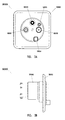
- Fig. 2 shows a drawing of the external appearance of an embodiment of the invention, in a front view (Fig. 2A) and a side view (Fig. 2B).
- This consists of a wall socket having the geometrical dimensions of an ordinary CATV network socket.
- the embodiment in question consists of a plastic support 10000 which surrounds a coaxial video connector 10001, a coaxial radio connector 10002, a power supply connector 10003, a coaxial cable modem connector 10005, and an MT-RJ optical adapter 10004.
- the side view in Fig. 2B shows the rear aluminium container 20000, in which is fitted the optoelectronic circuit for optical/electrical signal conversion which is shown in Figures 3, 4, 5 and 6 in four embodiments.
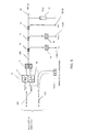
- Fig. 3 shows a first embodiment of the said optoelectronic circuit for converting optical signals to electrical signals.
- the AM broadband optical video signal arriving from the outgoing path along the optical fibre 200 is converted to an electrical signal by the broadband analogue receiver 10, which forms part of the broadband analogue transceiver 11.
- the said analogue receiver 10 converts the signal from optical to electrical and amplifies it by 20 dB.
- the signal converted to electrical form in this way is sent to the said electronic device for decoupling the outgoing path from the return path, this device being the diplexer 12 in the present embodiment.
- the diplexer 12 consists of a high-pass filter and a low-pass filter.
- the signal from the outgoing path is taken from the output of the high-pass filter by a first electronic 1/10 diverter 13 which sends it to the coaxial connector of the TV socket 10001, via the filter 14 which has the function of decoupling the return path from low-frequency disturbances originating from the television set.
- a second diverter 15 sends the outgoing path signal to the radio coaxial connector 10002 with the high-pass filter 16 whose function is similar to that of the filter 14.
- the 1/10 diverter 17 is designed to inject into the electrical line 400 the data signal of the return path, taken from the coaxial connector 10005 which is usually connected to a cable modem.
- the electrical signal which carries the data stream from the coaxial connector 10005 is sent by the diplexer 12 to a laser transmitter 18 of the VCSEL type with an output power of 0 dBm.
- This VCSEL is provided with an output power control circuit and converts the electrical signal carrying the return path data to an optical signal.
- an RF output 25 terminated with a 75 ohm resistor 19 allows the socket to be connected with any additional sockets.
- the present invention also comprises an MT-RJ optical connector 10004 which is connected to the optical fibre CATV network by two further optical fibres 203, 204.
- the set of fibres 200, 201, 203, 204 is a ribbon of 4 optical fibres.
- the TV signal at the socket measured as received from the optical network was found to have a CTB of 58 dB, a CSO of 57 dB and a C/N ratio of 46 dB, for a signal of 42 CENELEC optical carriers sent from the head end, in the band from 47 MHz to 860 MHz, using a CATV analogue transmitter made by the EMC company, with an output power of 13 dBm.
- Fig. 4 shows a variant of the embodiment described in Fig. 3, in which the diplexer 12 is replaced by a high-isolation splitter 21 for decoupling the outgoing path signals from the return path laser transmitter 18.
- This configuration enables a greater bandwidth to be used for the data signal of the return path, but has a lower capacity for isolating the outgoing path from the return path than the configuration with the diplexer 12.
- Fig. 5 shows a further variant of Fig. 3, in which optical couplers 301 and 302 are placed at the interface, making it possible to use a two-fibre link instead of a 4-fibre link, the same fibre being used to carry signals propagated in opposite directions.
- the set of two fibres 200 and 201 is a two-fibre ribbon.
- a further variant of the last-mentioned configuration is shown in Fig. 6.
Landscapes
- Engineering & Computer Science (AREA)
- Multimedia (AREA)
- Signal Processing (AREA)
- Optical Communication System (AREA)
- Two-Way Televisions, Distribution Of Moving Picture Or The Like (AREA)
Applications Claiming Priority (2)
| Application Number | Priority Date | Filing Date | Title |
|---|---|---|---|
| CH02380/00A CH700336B1 (it) | 2000-12-07 | 2000-12-07 | Presa ottica ricetrasmittente a muro. |
| CH238000 | 2000-12-07 |
Publications (2)
| Publication Number | Publication Date |
|---|---|
| EP1215906A2 true EP1215906A2 (de) | 2002-06-19 |
| EP1215906A3 EP1215906A3 (de) | 2005-02-16 |
Family
ID=4568888
Family Applications (1)
| Application Number | Title | Priority Date | Filing Date |
|---|---|---|---|
| EP01811124A Withdrawn EP1215906A3 (de) | 2000-12-07 | 2001-11-22 | Auf die Wand montierte optische Steckdose zum Empfangen und Senden |
Country Status (2)
| Country | Link |
|---|---|
| EP (1) | EP1215906A3 (de) |
| CH (1) | CH700336B1 (de) |
Cited By (4)
| Publication number | Priority date | Publication date | Assignee | Title |
|---|---|---|---|---|
| ES2275391A1 (es) * | 2005-03-01 | 2007-06-01 | Televes, S.A. | Toma de usuario para redes de telecomunicacion. |
| EP1881703A1 (de) | 2006-07-19 | 2008-01-23 | Televes, S.A. | Steckdose für Telekommunikationsnetze |
| DE102007027883A1 (de) * | 2007-06-18 | 2009-01-08 | Bktel Communications Gmbh | Verfahren und opto-elektrischer Wandler für Trägerfrequenz-Multiplexsysteme |
| US9223336B2 (en) | 2011-05-17 | 2015-12-29 | 3M Innovative Properties Company | Remote socket apparatus |
Family Cites Families (1)
| Publication number | Priority date | Publication date | Assignee | Title |
|---|---|---|---|---|
| US5808767A (en) * | 1996-05-30 | 1998-09-15 | Bell Atlantic Network Services, Inc | Fiber optic network with wavelength-division-multiplexed transmission to customer premises |
-
2000
- 2000-12-07 CH CH02380/00A patent/CH700336B1/it not_active IP Right Cessation
-
2001
- 2001-11-22 EP EP01811124A patent/EP1215906A3/de not_active Withdrawn
Cited By (5)
| Publication number | Priority date | Publication date | Assignee | Title |
|---|---|---|---|---|
| ES2275391A1 (es) * | 2005-03-01 | 2007-06-01 | Televes, S.A. | Toma de usuario para redes de telecomunicacion. |
| ES2275391B2 (es) * | 2005-03-01 | 2008-11-16 | Televes, S.A. | Toma de usuario para redes de telecomunicacion. |
| EP1881703A1 (de) | 2006-07-19 | 2008-01-23 | Televes, S.A. | Steckdose für Telekommunikationsnetze |
| DE102007027883A1 (de) * | 2007-06-18 | 2009-01-08 | Bktel Communications Gmbh | Verfahren und opto-elektrischer Wandler für Trägerfrequenz-Multiplexsysteme |
| US9223336B2 (en) | 2011-05-17 | 2015-12-29 | 3M Innovative Properties Company | Remote socket apparatus |
Also Published As
| Publication number | Publication date |
|---|---|
| CH700336B1 (it) | 2010-08-13 |
| EP1215906A3 (de) | 2005-02-16 |
Similar Documents
| Publication | Publication Date | Title |
|---|---|---|
| CN1886564B (zh) | 多波长双向光复用器 | |
| US7058966B2 (en) | Optical communication system for transmitting RF signals downstream and bidirectional telephony signals which also include RF control signals upstream | |
| US7664405B2 (en) | Pluggable optical diplexer/triplexer module | |
| US6775433B2 (en) | Deep fiber network with high speed data and video on demand | |
| JPS5925440A (ja) | テレビジヨン信号用分配ネツトワ−ク | |
| CN100592668C (zh) | 连接和测试粗波分多路复用光纤系统接口的方法 | |
| US20120051734A1 (en) | Status monitor transponder for an optical node of a network | |
| AU2002367223A1 (en) | Hybrid fiber optic and coaxial cable network node that contains a cable modem termination system | |
| EP1215906A2 (de) | Auf die Wand montierte optische Steckdose zum Empfangen und Senden | |
| EP1235434B1 (de) | Zweiwegnetzwerk zur Verteilung von Kabel-TV-Signalen an Endpunkte mittels optischer Fasern | |
| US8050565B2 (en) | Multiservice private network and interface modules for transporting, on such a network, data in different formats | |
| US20030063847A1 (en) | Deep fiber network architecture | |
| JP3759385B2 (ja) | ベースバンド信号およびパスバンド信号の双方を光学的に組み合わせる光通信システム | |
| US7197205B1 (en) | Deep fiber network with high speed data and video on demand | |
| Mogensen | Wide-band optical fibre local distribution systems | |
| Khoe et al. | TTOSS: An integrated subscriber system for direct and coherent detection | |
| US20060239691A1 (en) | Optical transceiver with connector | |
| Khoe et al. | Wavelength Division Multiplexing for Graded Index Polymer Optical Fibre Systems | |
| KR200475491Y1 (ko) | 광동축 혼합망의 광 수신분배 장치 및 이를 포함한 광동축 혼합망의 광 수신분배 확장모듈 | |
| KR200380894Y1 (ko) | 통신 및 방송 신호 통합 광전송 시스템 | |
| Bambach et al. | First installation of a novel all-digital access network system for distributive and interactive services | |
| US20020154368A1 (en) | Reverse path optical combining using an optical commutator | |
| JP2004526347A (ja) | 光広帯域伝送装置 |
Legal Events
| Date | Code | Title | Description |
|---|---|---|---|
| PUAI | Public reference made under article 153(3) epc to a published international application that has entered the european phase |
Free format text: ORIGINAL CODE: 0009012 |
|
| AK | Designated contracting states |
Kind code of ref document: A2 Designated state(s): AT BE CH CY DE DK ES FI FR GB GR IE IT LI LU MC NL PT SE TR |
|
| AX | Request for extension of the european patent |
Free format text: AL;LT;LV;MK;RO;SI |
|
| PUAL | Search report despatched |
Free format text: ORIGINAL CODE: 0009013 |
|
| AK | Designated contracting states |
Kind code of ref document: A3 Designated state(s): AT BE CH CY DE DK ES FI FR GB GR IE IT LI LU MC NL PT SE TR |
|
| AX | Request for extension of the european patent |
Extension state: AL LT LV MK RO SI |
|
| 17P | Request for examination filed |
Effective date: 20050329 |
|
| 17Q | First examination report despatched |
Effective date: 20050429 |
|
| AKX | Designation fees paid |
Designated state(s): AT BE CH CY DE DK ES FI FR GB GR IE IT LI LU MC NL PT SE TR |
|
| STAA | Information on the status of an ep patent application or granted ep patent |
Free format text: STATUS: THE APPLICATION IS DEEMED TO BE WITHDRAWN |
|
| 18D | Application deemed to be withdrawn |
Effective date: 20051110 |