EP1215936A2 - Lautsprecher - Google Patents
Lautsprecher Download PDFInfo
- Publication number
- EP1215936A2 EP1215936A2 EP01310349A EP01310349A EP1215936A2 EP 1215936 A2 EP1215936 A2 EP 1215936A2 EP 01310349 A EP01310349 A EP 01310349A EP 01310349 A EP01310349 A EP 01310349A EP 1215936 A2 EP1215936 A2 EP 1215936A2
- Authority
- EP
- European Patent Office
- Prior art keywords
- speaker
- barrier layer
- thermal barrier
- substrate
- electrode
- Prior art date
- Legal status (The legal status is an assumption and is not a legal conclusion. Google has not performed a legal analysis and makes no representation as to the accuracy of the status listed.)
- Withdrawn
Links
Images




Classifications
-
- H—ELECTRICITY
- H04—ELECTRIC COMMUNICATION TECHNIQUE
- H04R—LOUDSPEAKERS, MICROPHONES, GRAMOPHONE PICK-UPS OR LIKE ACOUSTIC ELECTROMECHANICAL TRANSDUCERS; ELECTRIC HEARING AIDS; PUBLIC ADDRESS SYSTEMS
- H04R23/00—Transducers other than those covered by groups H04R9/00 - H04R21/00
- H04R23/002—Transducers other than those covered by groups H04R9/00 - H04R21/00 using electrothermic-effect transducer
-
- H—ELECTRICITY
- H04—ELECTRIC COMMUNICATION TECHNIQUE
- H04R—LOUDSPEAKERS, MICROPHONES, GRAMOPHONE PICK-UPS OR LIKE ACOUSTIC ELECTROMECHANICAL TRANSDUCERS; ELECTRIC HEARING AIDS; PUBLIC ADDRESS SYSTEMS
- H04R23/00—Transducers other than those covered by groups H04R9/00 - H04R21/00
- H04R23/006—Transducers other than those covered by groups H04R9/00 - H04R21/00 using solid state devices
-
- H—ELECTRICITY
- H04—ELECTRIC COMMUNICATION TECHNIQUE
- H04R—LOUDSPEAKERS, MICROPHONES, GRAMOPHONE PICK-UPS OR LIKE ACOUSTIC ELECTROMECHANICAL TRANSDUCERS; ELECTRIC HEARING AIDS; PUBLIC ADDRESS SYSTEMS
- H04R1/00—Details of transducers, loudspeakers or microphones
- H04R1/20—Arrangements for obtaining desired frequency or directional characteristics
- H04R1/22—Arrangements for obtaining desired frequency or directional characteristics for obtaining desired frequency characteristic only
- H04R1/30—Combinations of transducers with horns, e.g. with mechanical matching means, i.e. front-loaded horns
Definitions
- the present invention relates to a speaker useful for the audio equipment, and more particularly to a speaker.
- An electro-acoustic transducer is well known in which an alternating current is introduced into a gold foil with only both ends fixed. If an alternating current is passed into the gold foil, the temperature of the gold foil changes, thereby causing a compression or expansion of the air nearby to produce an acoustic pressure.
- the gold foil for use is so thin as to fabricate and handle with difficulties, and is restricted in the input power, whereby a speaker is difficult to produce a sufficient sound volume.
- the present invention provides a speaker comprising a substrate, a thermal barrier layer formed on the substrate, and an exothermic electrode formed on the thermal barrier layer.
- This speaker can be easily handled because the exothermic electrode is fixed to the substrate, and can produce a large sound volume, because a heat not converted into the sound wave is radiated via the substrate and a large power can be input into the exothermic electrode. Owing to the use of the joule heating, the high acoustic efficiency can be attained, and the generated frequency band is broad. Further, the entire apparatus can be reduced in size, weight, and thickness. Further, the conformation of the exothermic electrode can be varied in arbitrary manner by changing the shape of the substrate, thereby controlling the directivity of generated sound wave at will.
- the thermal barrier layer may be formed by anodizing a part of the substrate. In this case, the normal semiconductor process may be utilized.
- the thermal barrier layer may be formed by supplying a material making up the thermal barrier layer on the substrate.
- the thermal barrier layer can be made of a material selected from a wide range of materials.
- the substrate may be made of silicone.
- the normal semiconductor process may be utilized
- the speaker may further comprise an acoustic horn for transmitting a sound wave arising in the vicinity of the exothermic electrode.
- the acoustic horn can adjust the transmission characteristic, the speaker can achieve the desired characteristics by increasing the sound pressure level in a low frequency band, for example.
- the surface of the exothermic electrode may be formed in a planar shape.
- the speaker can be adjusted to have a narrower directivity.
- the surface of the exothermic electrode may be formed in a curved shape.
- the speaker can be afforded with a wider directivity than when the exothermic electrode is formed in planar shape.
- the surface of the exothermic electrode may be formed in a shape of constituting at least a part of sphere.
- the speaker can be afforded with a wider directivity than when the exothermic electrode is formed in planar shape.
- the surface of the exothermic electrode is formed according to an almost spherical shape, whereby the speaker can have a non-directivity of radiating sound wave uniformly in substantially all directions.
- Fig. 1 is a cross-sectional view showing a speaker according to a first embodiment of the present invention.
- Fig. 2 is a perspective view showing the speaker according to the first embodiment of the invention.
- Fig. 3 is a graph showing the relation of input and output of energy Q, surface temperature T and generated sound wave P with respect to the temporal change of the alternating current I, when an AC electric field is applied to an exothermic electrode 3.
- Fig. 4 is a graph showing a frequency characteristic of the speaker according to the first embodiment of the invention.
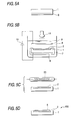
- Figs. 5A to 5D are views showing a manufacturing process for the speaker according to the first embodiment of the invention, in which Fig. 5A is a view showing a state where an ohmic electrode is formed, Fig. 5B is a view showing an anodization process, Fig. 5C is a view showing a quick thermal oxidation process, and Fig. 5D is a view showing a state where the exothermic electrode is formed.
- Fig. 6 is a view showing one example of exothermic electrode that is bent.
- Fig. 7 is a cross sectional view showing a speaker according to a second embodiment of the invention.
- Figs. 8A and 8B are views showing a speaker according to a third embodiment of the invention, in which Fig. 8A is a perspective view showing the speaker according to the third embodiment and Fig. 8B is a cross sectional view showing the speaker according to the third embodiment of the invention.
- Figs. 9A and 9B are views showing a speaker according to a fourth embodiment of the invention, in which Fig. 9A is a perspective view showing the speaker according to the fourth embodiment and Fig. 9B is a cross sectional view showing the speaker according to the fourth embodiment of the invention.
- Figs. 10A and 10B are views showing a speaker according to a fifth embodiment of the invention, in which Fig. 10A is a perspective view showing the speaker according to the fifth embodiment and Fig. 10B is a cross sectional view showing the speaker according to the fifth embodiment of the invention.
- Fig. 11 is a cross sectional view showing a speaker according to a sixth embodiment of the invention.
- Fig. 12 is a graph showing a frequency characteristic of the speaker according to the sixth embodiment of the invention.
- FIG. 1 is a cross-sectional view showing the speaker in the first embodiment
- Fig. 2 is a perspective view showing the speaker in the first embodiment.
- the speaker 100 comprises a silicone wafer 1 as a substrate, a thermal barrier layer 2 of an Si anodized film formed in rectangular shape by anodizing the silicone wafer 1, and an exothermic electrode 3 made of aluminum formed on the thermal barrier layer 2 in smaller rectangular shape than the thermal barrier layer 2.
- the shape of the silicone wafer 1 is rectangular, with a long side of 50mm, a short side of 20mm, and a thickness of 500 ⁇ m.
- the shape of the thermal barrier layer 2 is rectangular, with a long side of 45mm, a short side of 13mm, and a thickness of 20 ⁇ m.
- the shape of the exothermic electrode 3 is rectangular, with a long side of 40mm, a short side of 4mm, and a thickness of 330nm.
- an output terminal of an AC signal generator 21 is connected via a lead wire 3a to both ends of the exothermic electrode 3 (on the short side) . Then, if an AC electric field is applied, the temperature of the exothermic electrode 3 is varied like the alternating current due to the joule heating. At this time, a heat is hardly conducted to the thermal barrier layer 2 owing to a thermal barrier property of the thermal barrier layer 2, making the efficient heat exchange with the air in the vicinity of the surface of the exothermic electrode 3 to compress or expand the air, thereby producing an acoustic pressure . Aheat that can not be converted into acoustic pressure is radiated from the silicone wafer 1.
- Fig. 3 shows the relation of input or output of energy Q, surface temperature T and generated sound wave P, with respect to the temporal change of the alternating current I, when an AC electric field is applied to the exothermic electrode 3.
- the generated sound wave P has a double frequency of the applied AC frequency. It can be found that the phase of surface temperature T and generated sound wave P is delayed from the energy Q given to the exothermic electrode 3.
- a direct current with half or more the energy of the alternating current may be superposed on the alternating current.
- Fig. 4 shows a frequency characteristic of the speaker 100 that is measured by a microphone 22 placed at a position 1m away from the exothermic electrode 3, as shown in Figs. 1 and 2. As shown in Fig. 4, a sound pressure level of 90dB/W/m or greater is obtained in a frequency band of 10kHz or higher, and the sound pressure level drops with lower frequency.
- the rating of the AC signal generator 21 is from 0 to 100kHz, 30V, and 1A, no measurements are made in a higher frequency band, although the speaker 100 can produce a sound wave up to Giga-hertz band.
- Fig. 5A is a view showing a state where an ohmic electrode is formed
- Fig. 5B is a view showing a process of anodization
- Fig. 5C is a view showing a process of quick thermal oxidation
- Fig. 5D is a view showing a state where the exothermic electrode is formed.
- the thermal barrier layer 2 is formed by anodizing a part of the silicone wafer 1.
- Silicone of the silicone wafer 1 may be monocrystal, polycrystal, or amorphous, and take any crystal orientation. Also, it may be n-type doped, p-type doped, or non-doped.
- an ohmic electrode 6 is formed on one face of the silicone wafer 1 (i.e., a lower face in Fig. 5A) by vacuum deposition or sputtering, as shown in Fig. 5A. Also, an area except for an opening corresponding to a formation area of the thermal barrier layer 2 is masked with a masking material 7, as shown in Fig. 5B. Then, the substrate 1 is immersed in a mixture electrolyte solution 8 of fluoride and ethanol, and a platinum electrode 9 is arranged above the substrate 1 in Fig. 5B.
- a power source 10 is connected between the ohmic electrode 6 and the platinum electrode 9, and anodization is made at a low current (0.01 to 1A/cm 2 ), with the ohmic electrode 6 as anode and the platinum electrode 9 as cathode.
- anodization is performed by illuminating the substrate 1 with a lamp 11 to supply holes.
- the thermal barrier layer 2 formed by anodization becomes porous and is formed with micro pores having a diameter of about 2 to 100nm, when silicone of the silicone wafer 1 is n-type.
- the thermal barrier layer 2 has crystal lattice segmented and nanocrystalized, when silicone of the silicone wafer 1 is p-type. Further, holes that are carriers are consumed to make a depletion layer. In either case, the thermal barrier layer 2 can have a quite small thermal conductivity and a large electrical resistance. Then, the substrate 1 is taken out of the mixture electrolyte solution 8, and the masking material 7 and the ohmic electrode 6 are removed.
- the thermal barrier layer 2 may be heated by an infrared ray lamp 23 to make a quick thermal oxidation, as shown in Fig. 5C.
- the thermal barrier layer 2 that is an anodized layer has Si and SiOx mixed, but this ratio is adjusted through the quick thermal oxidation process, so that the optimal state can be obtained.
- the exothermic electrode 3 is formed by vacuum deposition or sputtering to fabricate the speaker 100, as shown in Fig. 5D.
- the silicone wafer is used, and anodized to form the thermal barrier layer, but instead of the silicone wafer, a substrate made of metal, alloy, or semiconductor that can be anodized may be employed.
- the thermal barrier layer may be formed by using the substrate made of metal, alloy or semiconductor, and laying down derivative, metal oxide, metal nitride, ceramic on the substrate by vacuum deposition, sputtering or CVD.
- the thermal barrier layer can be formed by coating a paste or suspension of derivative, metal oxide, metal nitride, or ceramics on the substrate by screen printing or spin coat, and then sintered.
- the substrate uses silicone as a material and the exothermic electrode uses aluminum as a material
- materials usable for the substrate or the exothermic electrode include simple substances of metal or its compound, such as Cu, Cr, Pt, Au, W, Ru, Ir, Al, Sc, Ti, V, Mn, Fe, Co, Ni, Zn, Ga, Y, Zr, Nb, Mo, Tc, Rh, Pd, Ag, Cd, Ln, Sn, Ta, Re, Os, Tl, Pb, La, Ce, Pr, Nd, Pm, Sm, Eu, Gd, Tb, Dy, Ho, Er, Tm, Yb, and Lu.
- the substrate or the exothermic electrode may be formed by laying down the metal or its compound as above cited.
- examples of usable material include metal oxides such as SiOx, LiOx, LiNx, NaOx, Kox, RbOx, CsOx, BeOx, MgOx, MgNx, CaOx, CaNx, SrOx, BaOx, ScOx, YOx, YNx, LaOx, LaNx, CeOx, PrOx, NdOx, SmOx, EuOx, GdOx, TbOx, DyOx, HoOx, ErOx, TmOx, YbOx, LuOx, TiOx, TiNx, ZrOx, ZrNx, HfOx, HfNx, ThOx, VOx, VNx, NbOx, TaOx, TaNx, CrOx, CrNx, MoOx, MoNx, WOx, WNx, MnOx, SiOx, LiOx, LiNx, NaOx, Kox, R
- the speaker 100 of this embodiment can be easily handled, because the exothermic electrode 3 is secured to the silicone wafer 1, and can produce a great volume of sound by inputting a large power into the exothermic electrode 3 because the heat not converted into sound wave is radiated via the silicone wafer 1. Also, owing to the use of the Joule heating, it is possible to obtain an essentially high acoustic conversion efficiency and a broad frequency band characteristic. Further, the speaker 1 is small and light, and of the thin type, whereby the entire apparatus can be reduced in size, weight and thickness as compared to the conventional speaker using a diaphragm.
- the exothermic electrode is formed in rectangular shape, but the exothermic electrode 31 may be formed in bent shape, as shown in Fig. 6.
- the impedance of the exothermic electrode can be controlled.
- a plurality of exothermic electrodes maybe provided, and driven in series or parallel.
- the shape of the substrate in the speaker of this invention is not limited.
- the substrate may take a shape like a primary curved surface, paraboloid, dome, sphere, or rugby ball.
- the shape of the exothermic electrode may be changed in accordance with the shape of the substrate to control the directivity of the generated sound wave.
- Fig. 7 is a cross-sectional view showing the speaker of the second embodiment.
- the thermal barrier layer 2 is formed by anodizing a part of the silicone wafer 1, a thermal barrier layer 2A of the speaker 200 in the second embodiment is formed on a substrate 1A, as shown in Fig. 6.
- the thermal barrier layer 2A can be formed by laying down derivative, metal oxide, metal nitride, or ceramics on the substrate 1A by sputtering or CVD.
- the thermal barrier layer 2A can be formed by coating a paste or suspension of derivative, metal oxide, metal nitride, or ceramics on the substrate 1A by screen printing or spin coat, and then sintered.
- an exothermic electrode 3A is formed on the thermal barrier layer 2A.
- the materials of the substrate 1A, the thermal barrier layer 2A and the exothermic electrode 3A may be those listed in the first embodiment.
- the shape of the exothermic electrode may be arbitrary. Also, a plurality of exothermic electrodes may be provided, and driven in series or parallel.
- Fig. 8A is a perspective view showing the speaker in the third embodiment
- Fig. 8B is a cross-sectional view showing the speaker of the third embodiment.
- the speaker 300 of this embodiment comprises a substrate 1B of curved shape, as shown in Fig. 8A and 8B.
- a thermal barrier layer 2B composed of an anodized film is formed on a part of the substrate 1B, and an exothermic electrode 3B is formed on the thermal barrier layer 2B.
- the thermal barrier layer 2B and the exothermic electrode 3B are curved according to a surface configuration of the substrate 1B constituting a primary curved face .
- the materials of the substrate 1B, the thermal barrier layer 2B and the exothermic electrode 3B may be those listed in the first embodiment.
- the thermal barrier layer may be formed on the substrate in the same manner as in the second embodiment.
- the shape of the exothermic electrode may be arbitrary. Also, a plurality of exothermic electrodes may be provided, and driven in series or parallel.
- Fig. 9A is a perspective view showing the speaker in the fourth embodiment
- Fig. 9B is a cross-sectional view showing the speaker of the fourth embodiment.
- the speaker 400 of this embodiment comprises a substrate 1C of hemispherical surface shape, as shown in Fig. 9A and 9B.
- a thermal barrier layer 2C is formed on the outer surface of the substrate 1C by anodizing the substrate 1C, and an exothermic electrode 3C is formed on the outer surface of the thermal barrier layer 2C.
- the thermal barrier layer 2C and the exothermic electrode 3C are curved according to a surface configuration of the substrate 1C constituting a part of sphere.
- the exothermic electrode 3C is formed in a shape constituting a part of sphere to widen the directivity of generated sound wave.
- the materials of the substrate 1C, the thermal barrier layer 2C and the exothermic electrode 3C may be those listed in the first embodiment.
- the thermal barrier layer may be formed on the substrate in the same manner as in the second embodiment.
- the shape of the exothermic electrode may be arbitrary. Also, a plurality of exothermic electrodes may be provided, and driven in series or parallel.
- Fig. 10A is a perspective view showing the speaker in the fifth embodiment
- Fig. 10B is a cross-sectional view showing the speaker of the fifth embodiment.
- the speaker 500 of this embodiment comprises a substrate 1D of spherical shape, as shown in Fig. 10A and 10B.
- a thermal barrier layer 2D is formed on the outer surface of abase substance 1D by anodizing a part of the base substance 1D, and an exothermic electrode 3D is formed on the outer surface of the thermal barrier layer 2D.
- the exothermic electrode 3D is formed according to a spherical shape, whereby the speaker has a non-directivity of radiating sound wave uniformly in substantially all directions.
- the thermal barrier layer may be formed on the substrate in the same manner as in the second embodiment.
- the materials of the base substance 1D, the thermal barrier layer 2D and the exothermic electrode 3D may be those listed in the first embodiment.
- the shape of the exothermic electrode may be arbitrary. Also, a plurality of exothermic electrodes may be provided, and driven in series or parallel.
- Fig. 11 is a cross-sectional view showing the speaker of the sixth embodiment
- Fig. 12 is a graph showing a frequency characteristic for the speaker of the sixth embodiment.
- the speaker 600 of the sixth embodiment has an acoustic horn 40 added to the speaker 100 of the first embodiment.
- the acoustic horn 40 presents a shape of sound path enlarging in section from a throat portion 40a positioned near the exothermic electrode 3 to an opening portion 40b.
- the speaker 600 of the sixth embodiment has a higher sound pressure level than the speaker 100 of the first embodiment.
- the speaker 600 that is more efficient particularly in a low frequency band approaches a flat frequency characteristic as a whole.
- the speaker 600 has a sound pressure level of 95dB/W/m or greater at 1kHz, 10kHz and 100kHz, 90dB/W/m or greater at 10Hz and 100Hz, and a characteristic of quite wide band, as shown in Fig. 12.
Landscapes
- Physics & Mathematics (AREA)
- Engineering & Computer Science (AREA)
- Acoustics & Sound (AREA)
- Signal Processing (AREA)
- Electrostatic, Electromagnetic, Magneto- Strictive, And Variable-Resistance Transducers (AREA)
- Laminated Bodies (AREA)
Applications Claiming Priority (2)
| Application Number | Priority Date | Filing Date | Title |
|---|---|---|---|
| JP2000381409A JP2002186097A (ja) | 2000-12-15 | 2000-12-15 | スピーカ |
| JP2000381409 | 2000-12-15 |
Publications (2)
| Publication Number | Publication Date |
|---|---|
| EP1215936A2 true EP1215936A2 (de) | 2002-06-19 |
| EP1215936A3 EP1215936A3 (de) | 2003-07-02 |
Family
ID=18849410
Family Applications (1)
| Application Number | Title | Priority Date | Filing Date |
|---|---|---|---|
| EP01310349A Withdrawn EP1215936A3 (de) | 2000-12-15 | 2001-12-11 | Lautsprecher |
Country Status (3)
| Country | Link |
|---|---|
| US (1) | US20020076070A1 (de) |
| EP (1) | EP1215936A3 (de) |
| JP (1) | JP2002186097A (de) |
Cited By (6)
| Publication number | Priority date | Publication date | Assignee | Title |
|---|---|---|---|---|
| WO2006011650A3 (en) * | 2004-07-27 | 2006-03-23 | Matsushita Electric Works Ltd | Acoustic wave sensor |
| EP1599068A4 (de) * | 2003-02-28 | 2009-04-22 | Univ Tokyo Agriculture & Technology Tlo Co Ltd | Thermisch erregte schallwellenerzeugungseinrichtung |
| EP1916870A4 (de) * | 2005-10-26 | 2009-07-29 | Panasonic Elec Works Co Ltd | Druckwellengenerator und herstellungsverfahren dafür |
| EP2217006A1 (de) * | 2009-02-04 | 2010-08-11 | Oticon A/S | Hörgerät |
| CN1954640B (zh) * | 2004-04-28 | 2011-07-27 | 松下电工株式会社 | 压力波产生装置及其制造方法 |
| GB2601835A (en) * | 2020-12-14 | 2022-06-15 | Soliton Holdings Corp | Apparatuses based on jet-effect and thermo-electric effect |
Families Citing this family (45)
| Publication number | Priority date | Publication date | Assignee | Title |
|---|---|---|---|---|
| US7476925B2 (en) | 2001-08-30 | 2009-01-13 | Micron Technology, Inc. | Atomic layer deposition of metal oxide and/or low asymmetrical tunnel barrier interploy insulators |
| US7160577B2 (en) | 2002-05-02 | 2007-01-09 | Micron Technology, Inc. | Methods for atomic-layer deposition of aluminum oxides in integrated circuits |
| US7589029B2 (en) | 2002-05-02 | 2009-09-15 | Micron Technology, Inc. | Atomic layer deposition and conversion |
| US7192892B2 (en) | 2003-03-04 | 2007-03-20 | Micron Technology, Inc. | Atomic layer deposited dielectric layers |
| JP2005291941A (ja) * | 2004-03-31 | 2005-10-20 | Matsushita Electric Works Ltd | 超音波センサ及び同センサ用の送波素子 |
| JP4505672B2 (ja) * | 2004-04-28 | 2010-07-21 | パナソニック電工株式会社 | 圧力波発生装置及びその製造方法 |
| JP4617710B2 (ja) * | 2004-04-28 | 2011-01-26 | パナソニック電工株式会社 | 圧力波発生素子 |
| JP4649929B2 (ja) * | 2004-09-27 | 2011-03-16 | パナソニック電工株式会社 | 圧力波発生素子 |
| JP4617803B2 (ja) * | 2004-09-27 | 2011-01-26 | パナソニック電工株式会社 | 圧力波発生素子 |
| JP4682573B2 (ja) * | 2004-09-27 | 2011-05-11 | パナソニック電工株式会社 | 圧力波発生素子 |
| US7662729B2 (en) | 2005-04-28 | 2010-02-16 | Micron Technology, Inc. | Atomic layer deposition of a ruthenium layer to a lanthanide oxide dielectric layer |
| US7572695B2 (en) | 2005-05-27 | 2009-08-11 | Micron Technology, Inc. | Hafnium titanium oxide films |
| US7927948B2 (en) | 2005-07-20 | 2011-04-19 | Micron Technology, Inc. | Devices with nanocrystals and methods of formation |
| JP4742907B2 (ja) * | 2006-02-23 | 2011-08-10 | パナソニック電工株式会社 | 圧力波発生素子およびその製造方法 |
| JP5116269B2 (ja) * | 2006-08-25 | 2013-01-09 | 株式会社ジャパンディスプレイイースト | 画像表示装置 |
| EP2061098A4 (de) | 2006-09-05 | 2011-06-01 | Pioneer Corp | Thermische schallerzeugungseinrichtung |
| US8270639B2 (en) | 2008-04-28 | 2012-09-18 | Tsinghua University | Thermoacoustic device |
| US8249279B2 (en) | 2008-04-28 | 2012-08-21 | Beijing Funate Innovation Technology Co., Ltd. | Thermoacoustic device |
| US8259967B2 (en) | 2008-04-28 | 2012-09-04 | Tsinghua University | Thermoacoustic device |
| US8452031B2 (en) | 2008-04-28 | 2013-05-28 | Tsinghua University | Ultrasonic thermoacoustic device |
| US8259968B2 (en) | 2008-04-28 | 2012-09-04 | Tsinghua University | Thermoacoustic device |
| CN101820571B (zh) * | 2009-02-27 | 2013-12-11 | 清华大学 | 扬声器系统 |
| CN101656907B (zh) | 2008-08-22 | 2013-03-20 | 清华大学 | 音箱 |
| CN101713531B (zh) | 2008-10-08 | 2013-08-28 | 清华大学 | 发声照明装置 |
| CN101715155B (zh) | 2008-10-08 | 2013-07-03 | 清华大学 | 耳机 |
| CN101715160B (zh) | 2008-10-08 | 2013-02-13 | 清华大学 | 柔性发声装置及发声旗帜 |
| US8300855B2 (en) | 2008-12-30 | 2012-10-30 | Beijing Funate Innovation Technology Co., Ltd. | Thermoacoustic module, thermoacoustic device, and method for making the same |
| US8325947B2 (en) | 2008-12-30 | 2012-12-04 | Bejing FUNATE Innovation Technology Co., Ltd. | Thermoacoustic device |
| CN101771922B (zh) | 2008-12-30 | 2013-04-24 | 清华大学 | 发声装置 |
| TWI411314B (zh) * | 2009-01-16 | 2013-10-01 | Beijing Funate Innovation Tech | 熱致發聲裝置 |
| TWI382772B (zh) * | 2009-01-16 | 2013-01-11 | Beijing Funate Innovation Tech | 熱致發聲裝置 |
| US8231795B2 (en) | 2009-05-01 | 2012-07-31 | Avago Technologies Wireless Ip (Singapore) Pte. Ltd. | Micromachined horn |
| CN101922755A (zh) | 2009-06-09 | 2010-12-22 | 清华大学 | 取暖墙 |
| CN101943850B (zh) | 2009-07-03 | 2013-04-24 | 清华大学 | 发声银幕及使用该发声银幕的放映系统 |
| CN101990152B (zh) | 2009-08-07 | 2013-08-28 | 清华大学 | 热致发声装置及其制备方法 |
| CN102006542B (zh) | 2009-08-28 | 2014-03-26 | 清华大学 | 发声装置 |
| CN102023297B (zh) | 2009-09-11 | 2015-01-21 | 清华大学 | 声纳系统 |
| CN102034467B (zh) | 2009-09-25 | 2013-01-30 | 北京富纳特创新科技有限公司 | 发声装置 |
| CN102056064B (zh) | 2009-11-06 | 2013-11-06 | 清华大学 | 扬声器 |
| CN102056065B (zh) | 2009-11-10 | 2014-11-12 | 北京富纳特创新科技有限公司 | 发声装置 |
| CN102065363B (zh) * | 2009-11-16 | 2013-11-13 | 北京富纳特创新科技有限公司 | 发声装置 |
| JP2012054762A (ja) * | 2010-09-01 | 2012-03-15 | Nippon Hoso Kyokai <Nhk> | 薄膜音波出力装置 |
| JP2013187845A (ja) * | 2012-03-09 | 2013-09-19 | Nippon Hoso Kyokai <Nhk> | スピーカー素子 |
| JP2018133625A (ja) * | 2017-02-13 | 2018-08-23 | ヤマハファインテック株式会社 | 熱音響装置及び音波検査装置 |
| WO2025169761A1 (ja) * | 2024-02-08 | 2025-08-14 | 株式会社村田製作所 | 圧力波発生素子 |
Family Cites Families (5)
| Publication number | Priority date | Publication date | Assignee | Title |
|---|---|---|---|---|
| DE1277374B (de) * | 1964-09-30 | 1968-09-12 | Hitachi Ltd | Mechanisch-elektrischer Wandler |
| US3407273A (en) * | 1965-01-08 | 1968-10-22 | Stanford Research Inst | Thermoacoustic loudspeaker |
| DE2417962A1 (de) * | 1974-04-11 | 1975-10-23 | Max Planck Gesellschaft | Verfahren zur umwandlung von schwankungen eines koerpers in schwankungen einer elektrischen spannung und umgekehrt |
| US4638207A (en) * | 1986-03-19 | 1987-01-20 | Pennwalt Corporation | Piezoelectric polymeric film balloon speaker |
| JPH03140100A (ja) * | 1989-10-26 | 1991-06-14 | Fuji Xerox Co Ltd | 電気音響変換方法及びその為の装置 |
-
2000
- 2000-12-15 JP JP2000381409A patent/JP2002186097A/ja active Pending
-
2001
- 2001-12-11 US US10/011,770 patent/US20020076070A1/en not_active Abandoned
- 2001-12-11 EP EP01310349A patent/EP1215936A3/de not_active Withdrawn
Cited By (12)
| Publication number | Priority date | Publication date | Assignee | Title |
|---|---|---|---|---|
| EP1599068A4 (de) * | 2003-02-28 | 2009-04-22 | Univ Tokyo Agriculture & Technology Tlo Co Ltd | Thermisch erregte schallwellenerzeugungseinrichtung |
| CN1954640B (zh) * | 2004-04-28 | 2011-07-27 | 松下电工株式会社 | 压力波产生装置及其制造方法 |
| WO2006011650A3 (en) * | 2004-07-27 | 2006-03-23 | Matsushita Electric Works Ltd | Acoustic wave sensor |
| KR100915486B1 (ko) * | 2004-07-27 | 2009-09-03 | 파나소닉 전공 주식회사 | 음파 감지기 |
| CN1989418B (zh) * | 2004-07-27 | 2010-05-05 | 松下电工株式会社 | 声波探测器 |
| US8254209B2 (en) | 2004-07-27 | 2012-08-28 | Panasonic Corporation | Acoustic wave sensor |
| EP1916870A4 (de) * | 2005-10-26 | 2009-07-29 | Panasonic Elec Works Co Ltd | Druckwellengenerator und herstellungsverfahren dafür |
| US7881157B2 (en) | 2005-10-26 | 2011-02-01 | Panasonic Electric Works Co., Ltd, | Pressure wave generator and production method therefor |
| EP2217006A1 (de) * | 2009-02-04 | 2010-08-11 | Oticon A/S | Hörgerät |
| US8644540B2 (en) | 2009-02-04 | 2014-02-04 | Oticon A/S | Hearing device |
| GB2601835A (en) * | 2020-12-14 | 2022-06-15 | Soliton Holdings Corp | Apparatuses based on jet-effect and thermo-electric effect |
| GB2601835B (en) * | 2020-12-14 | 2023-01-25 | Soliton Holdings Corp | Apparatuses based on jet-effect and thermoelectric effect |
Also Published As
| Publication number | Publication date |
|---|---|
| EP1215936A3 (de) | 2003-07-02 |
| US20020076070A1 (en) | 2002-06-20 |
| JP2002186097A (ja) | 2002-06-28 |
Similar Documents
| Publication | Publication Date | Title |
|---|---|---|
| EP1215936A2 (de) | Lautsprecher | |
| Li et al. | Preparation of sandwich-like NiCo2O4/rGO/NiO heterostructure on nickel foam for high-performance supercapacitor electrodes | |
| DE69811976T2 (de) | Elektronenemissionsvorrichtung | |
| DE69827340T2 (de) | Elektronenemissionsvorrichtung und Anzeigevorrichtung unter Verwendung derselben | |
| Ma et al. | Self-supported formation of hierarchical NiCo 2 O 4 tetragonal microtubes with enhanced electrochemical properties | |
| Wang et al. | α-Fe 2 O 3 nanotubes with superior lithium storage capability | |
| Crisostomo et al. | New synthetic route, characterization, and electrocatalytic activity of nanosized manganite | |
| DE69806287T2 (de) | Elektronenemissionsvorrichtung und Anzeigevorrichtung unter Verwendung derselben | |
| DE69800382T2 (de) | Elektronenemissionsvorrichtung und Anzeigevorrichtung unter Verwendung derselben | |
| US7936112B2 (en) | Apparatus and method for converting energy | |
| You et al. | Designing binary Ru–Sn oxides with optimized performances for the air electrode of rechargeable zinc–air batteries | |
| Liu et al. | Self-assembled hierarchical yolk–shell structured NiO@ C from metal–organic frameworks with outstanding performance for lithium storage | |
| US20110274297A1 (en) | Thermoacoustic device | |
| US6400070B1 (en) | Electron emission device and display device using the same | |
| US6023125A (en) | Electron emission device and display using the same | |
| TW201743199A (zh) | 聲音輸出裝置 | |
| Ni et al. | Synthesis and characterization of hierarchical NiO nanoflowers with porous structure | |
| EP0896355B1 (de) | Elektronenemissionsvorrichtung und Anzeigevorrichtung unter Verwendung derselben | |
| CN107274880A (zh) | 一种非线性磁力负刚度主动吸声装置 | |
| TW201709250A (zh) | 太赫茲反射速調管及微米太赫茲反射速調管陣列 | |
| JP5171988B2 (ja) | 電子放出素子、電子放出素子を用いた表示装置及び電子放出素子の製造方法 | |
| JP3698382B2 (ja) | 電子放出素子及びこれを用いた表示装置 | |
| US6278230B1 (en) | Electron emission device and display device using the same | |
| Datta et al. | Controlled Ti seed layer assisted growth and field emission properties of Pb (Zr0. 52Ti0. 48) O3 nanowire arrays | |
| JP2008113280A (ja) | マイクロホン |
Legal Events
| Date | Code | Title | Description |
|---|---|---|---|
| PUAI | Public reference made under article 153(3) epc to a published international application that has entered the european phase |
Free format text: ORIGINAL CODE: 0009012 |
|
| AK | Designated contracting states |
Kind code of ref document: A2 Designated state(s): AT BE CH CY DE DK ES FI FR GB GR IE IT LI LU MC NL PT SE TR |
|
| AX | Request for extension of the european patent |
Free format text: AL;LT;LV;MK;RO;SI |
|
| PUAL | Search report despatched |
Free format text: ORIGINAL CODE: 0009013 |
|
| AK | Designated contracting states |
Designated state(s): AT BE CH CY DE DK ES FI FR GB GR IE IT LI LU MC NL PT SE TR |
|
| AX | Request for extension of the european patent |
Extension state: AL LT LV MK RO SI |
|
| 17P | Request for examination filed |
Effective date: 20031230 |
|
| AKX | Designation fees paid |
Designated state(s): DE FR GB |
|
| STAA | Information on the status of an ep patent application or granted ep patent |
Free format text: STATUS: THE APPLICATION IS DEEMED TO BE WITHDRAWN |
|
| 18D | Application deemed to be withdrawn |
Effective date: 20070703 |