EP1215977B1 - Appareil de nettoyage pour peignes et brosses a cheveux - Google Patents
Appareil de nettoyage pour peignes et brosses a cheveux Download PDFInfo
- Publication number
- EP1215977B1 EP1215977B1 EP00969803A EP00969803A EP1215977B1 EP 1215977 B1 EP1215977 B1 EP 1215977B1 EP 00969803 A EP00969803 A EP 00969803A EP 00969803 A EP00969803 A EP 00969803A EP 1215977 B1 EP1215977 B1 EP 1215977B1
- Authority
- EP
- European Patent Office
- Prior art keywords
- whips
- whip
- rotating shaft
- hair
- previous
- Prior art date
- Legal status (The legal status is an assumption and is not a legal conclusion. Google has not performed a legal analysis and makes no representation as to the accuracy of the status listed.)
- Expired - Lifetime
Links
- 238000004140 cleaning Methods 0.000 title description 9
- 210000001520 comb Anatomy 0.000 title description 6
- 230000005540 biological transmission Effects 0.000 claims description 10
- 230000001681 protective effect Effects 0.000 claims description 10
- 238000007689 inspection Methods 0.000 claims description 5
- 238000005273 aeration Methods 0.000 claims description 3
- 208000027418 Wounds and injury Diseases 0.000 description 3
- 230000036961 partial effect Effects 0.000 description 3
- 230000006378 damage Effects 0.000 description 2
- 230000002452 interceptive effect Effects 0.000 description 2
- 230000000670 limiting effect Effects 0.000 description 2
- 238000000034 method Methods 0.000 description 2
- 238000004804 winding Methods 0.000 description 2
- 230000001133 acceleration Effects 0.000 description 1
- 230000001680 brushing effect Effects 0.000 description 1
- 238000001816 cooling Methods 0.000 description 1
- 230000008878 coupling Effects 0.000 description 1
- 238000010168 coupling process Methods 0.000 description 1
- 238000005859 coupling reaction Methods 0.000 description 1
- 230000000694 effects Effects 0.000 description 1
- 239000012634 fragment Substances 0.000 description 1
- 230000005484 gravity Effects 0.000 description 1
- 208000014674 injury Diseases 0.000 description 1
- 239000000463 material Substances 0.000 description 1
- 239000002184 metal Substances 0.000 description 1
- 230000002093 peripheral effect Effects 0.000 description 1
- 230000000717 retained effect Effects 0.000 description 1
Images



Classifications
-
- A—HUMAN NECESSITIES
- A45—HAND OR TRAVELLING ARTICLES
- A45D—HAIRDRESSING OR SHAVING EQUIPMENT; EQUIPMENT FOR COSMETICS OR COSMETIC TREATMENTS, e.g. FOR MANICURING OR PEDICURING
- A45D24/00—Hair combs for care of the hair; Accessories therefor
- A45D24/40—Manually actuated comb cleaners
- A45D24/44—Manually actuated comb cleaners as separate apparatus
- A45D24/46—Manually actuated comb cleaners as separate apparatus with roller brushes
-
- A—HUMAN NECESSITIES
- A46—BRUSHWARE
- A46B—BRUSHES
- A46B17/00—Accessories for brushes
- A46B17/06—Devices for cleaning brushes after use
Definitions
- US-A-3 348 253 discloses a device for removing hair from a hair brush and/or a comb comprising two elongated brushes and rotating in opposite directions which comb the hair out of the hair brush into a lower hair receiving compartment.
- NL-A-9 300 585 and US-A-3 805 318 disclose apparatuses according to the preamble of claim 1, where however the rotating shaft/s is/are actually one/two bristled brush/es.
- a brushing action implies a relevant friction force between a cleaning brush and an hair brush to be cleaned, causing i.a. both to become worn.
- the problem at the basis of the present invention is that of eliminating the above disadvantages, by creating an apparatus for removing hair entangled among the teeth of combs or among the bristles of brushes, which should clean combs and brushes in an effective, fast and hygienic way.
- Such an apparatus should preferably have reasonable weight and size, such as to be easily placed on a bathroom console or on the sink bench at the hairdressers.
- the invention relates to an apparatus for removing hair from the teeth of a comb or the bristles of a brush according to claim 1; preferred embodiments are given in claims 2 to 18.
- Each whip is so spaced apart from any other possible whip of a same rotating shaft as not to interfere, in use, therewith, whereby each whip of a same rotating shaft acts on a comb or a brush individually.
- the or each whip hits the comb or brush arranged at the receiving position, catching or breaking any hair entangled among the teeth or the bristles, and the hair or fragment of hair, thus freed, is removed by the suction air stream.
- the whips are distributed along an end portion of the at least one rotating shaft.
- the at least one rotating shaft is preferably horizontally oriented, thus the whips rotate in a vertical plane.
- means for collecting the hair removed by the suction means is comprised.
- the apparatus preferably comprises a first and a second parallel rotating shafts, provided with at least one respective whip.
- the first and the second shaft are counter-rotating in such directions that the respective whips converge from the receiving position towards the suction air stream.
- the whips convey the removed hair towards the air stream, thus reducing the probability of being scattered in the environment.
- the rotating shafts preferably are at a mutual distance that is essentially equal to the length of the whips.
- the whips of the first rotating shaft may then be axially staggered with respect to the whips of the second rotating shaft.
- the whips of the first rotating shaft and the whips of the second rotating shaft may extend in a common transversal plane but in out-of-phase radial positions.
- the centrifugal acceleration will cause the whips to adopt the maximum radial extension during rotation, still they will be able to bend if hit by the teeth or bristles or by the same body of the comb or brush, thus preventing breakage and/or damage to other parts.
- flexible or non-flexible whips can be mounted as articulated.
- each whip may consist of the free end of a continuous thread wound on a reel.
- the apparatus further has scrapers that are tangential to the rotating shafts and/or to the whip-holder hubs, for preventing hair from winding around them.
- the apparatus exhibits a containing box-shaped body provided with an aperture suitable to allow the exit of the whips towards the receiving position and the inlet of air of the suction air stream, and provided with aeration splits.
- the aperture of the box-shaped body is arranged at its top. Besides being particularly practical in use, such a configuration favours the removal of disentangled hair, which tends to fall due to gravity force.
- the apparatus may comprise a protective shell at the aperture of the box-shaped body, so as to prevent the risk of injuries, particularly in case of accidental detachment of the whips.
- the protective shell preferably has at least one access door urged in the closed position and interacting with a safety switch.
- the box-shaped body comprises an extractable drawer-like container for collecting the hair, provided with a hair-retaining filter.
- the action of cleaning the filter is facilitated.
- the extractable drawer is preferably sealingly closable.
- the hair-collecting extractable drawer has a variable height so as to be inserted underneath the motor.
- the box-shaped body may have an inspection door at the whips.
- a common motor is present, typically an electric motor, for operating both a fan of the suction means, and the at least one rotating shaft. Besides limiting the size and the power required by the apparatus, this expedient ensures the simultaneousness of the disentangling and suction actions.
- the apparatus then has first motion transmission means between a driving shaft of the electric motor and the first rotating shaft and second motion transmission means between the first rotating shaft and the second rotating shaft.
- the first motion transmission means can consist of a belt drive, preferably at an intermediate portion of the first rotating shaft.
- the second motion transmission means can comprise two gearwheels respectively coupled to the first and to the second rotating shaft and engaged with one another, or two rubber-top pulleys coupled through friction.
- Gearwheels or rubber-top pulleys are preferably arranged at an end of the rotating shafts, preferably at the end opposed to that from which the at least one respective whip extends.
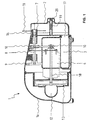
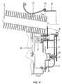
- Apparatus 1 shown in Figure 1 comprises a box-shaped body 1a enclosing all of the elements suitable to the operation of apparatus 1, such as a motor 6, typically electrical, whose driving shaft 18 provides both to operating a fan 13, and - through a belt drive 10 - to operating horizontal shafts 8 coupled through gearwheels 9 at a first end, and carrying, at the opposed end, hubs 7 with respective whips 11.
- a motor 6 typically electrical
- driving shaft 18 provides both to operating a fan 13
- - through a belt drive 10 - to operating horizontal shafts 8 coupled through gearwheels 9 at a first end, and carrying, at the opposed end, hubs 7 with respective whips 11.
- a whip inspection door 2 is represented as frontally mounted, for example through a screw coupling 19, 20.
- the box-shaped body 1a exhibits an aperture 16 suitable to allow the exit of whips 11 during the rotation of shafts 8. Moreover, aperture 16 allows the inlet of air, which is sucked by fan 13 through an air manifold 12 and a passage 17, connected to a preferably extractable drawer-like container 3 for collecting the hair and other removed debris. Thus, between aperture 16 and passage 17 there is defined an essentially vertical suction duct below the rotating shafts 8.
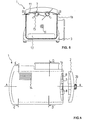
- FIG. 2 The sectional view of Figure 2 allows the plan view of the air manifold 12, connected to a filter 5 housed within container 3, in turn sealingly closed by a cover 4, shown as removed from its seat.
- the whips of the two shafts 8 are axially staggered.
- the rotating shafts 8 exhibit, as shown, a mutual distance that is essentially equal to the length of whips 11.
- the whips of the first rotating shaft 8a and the whips of the second rotating shaft 8b could extend in a common transversal plane, but in out-of-phase radial positions.
- Figure 3 represents the side pattern of manifold 12 which, starting from fan 13, reaches filter 5.
- FIG. 4 clarifies the connection between the driving shaft 18, the fan 13 and the rotating shafts 8 through transmission 10 and gearwheels 9.
- container 3 for collecting the hair is visible, having a variable height so as to be inserted under motor 6.
- Figure 5 illustrates scrapers 15 acting at the whip-holder hubs 7 for preventing the winding of hair around the whip-holder hubs 7.
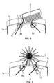
- Figures 7-9 schematically show the action of the disentangling whips 11.
- Figures 8 and 9 illustrate the manner how the whips 11, made as flexible, yield when on their path they meet the bristles of a brush S, or respectively, the teeth of a comb P, arranged in the receiving position.
- apparatus 1 More in detail, the operation of apparatus 1 is as follows.
- a condition of continuous suction and discharge is thus stabilised, suitable for collecting and retaining all residuals that come in the proximity of aperture 16, where the disentangling whips 1 act.
- whips 11 which during the rotation of rotating shafts 8, cyclically pass through the receiving position of comb P or brush S, in the proximity of aperture 16, where they effectively catch and break the hair and other residues entangled among the bristles of brush S or the teeth of comb P.
- the motion of shafts 8 and thus, of whips 11 mounted on hubs 7, integral with them, is counter-rotating, that is, the first on the left in Figure 7 rotates in clockwise direction, and the second rotates in counterclockwise direction; this allows conveying what removed towards the centre, where the suction air flow does not have difficulty to catch residuals and hair and convey them to the collecting container 3.
- whips 11 are always dipped in the suction air stream, which favours removal of any hair entangled in the whips 11 themselves.
- the most functional whips 11 will be selected in conformity with the tools they have to clean.
- they can be rigid or more or less flexible, and/or articulatedly mounted and orbitally mounted on the entrainment hubs 7.
- each whip 11 may consist of the free end of a continuous thread, for example an elastic thread, wound on a reel 21.
- Reel 21 is housed within a coaxial seat of hub 7, with friction disks 25 interposed.
- Hub 7 has a hole 22 in its side wall so as to allow the exit of whip 11.
- An adjusting screw 23, provided with an end rubber 24, allows constraining reel 21 with hub 7 and shaft 8 and, when loosened, it allows extracting a new portion of thread to renew whip 11.
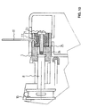
- a protective shell 26 arranged at aperture 16. Since the whips are subject to centrifugal force, in case of detachment of a whip 11 during operation of the apparatus, it would be retained by the protective shell 26.
- the protective shell 26 shown in Figure 11 is provided with a rear access door 27 and with a front access door 28, shown in opened position. Doors 27 and 28 are urged in the closed position of protective shell 26, as shown by the arrows, for example by torsion springs at the hinge points 29, 30.
- the front access door 28 exhibits a projection 31 which, in the illustrated opened position, co-operates with a safety switch 32, connected to motor 6 through electrical connections, not shown.
- the illustrated safety switch 32 is of the push-button type, and it actuates motor 6 only when the front door 28 is held downwards, against the force of the torsion spring at hinge 30. Thus, requiring the use of both hands, apparatus 1 is safe also against the actuation by children.
- separate motors could be provided for actuating the fan 13 and the rotating shafts 8, as well as different motion transmission systems.
- two separate transmissions could be provided for the two rotating shafts 8, and the transmissions can be implemented through gears, belts or rubber-top pulleys coupled through friction.
- whips As regards the number of whips, it can be understood that several embodiments can be devised. In fact, while on the one hand a single rotating shaft with a single whip could suffice, on the other hand the single rotating shaft or each rotating shaft could be provided with at most two whips distributed along a circumference or axially spaced.
- hair collecting means As an alternative to the extractable drawer provided with filter, as hair collecting means it could be possible, for example, to use a collecting bag as those used in vacuum cleaners.
Landscapes
- Brushes (AREA)
Claims (18)
- Appareil (1) pour retirer des cheveux d'entre les dents d'un peigne (P) ou des poils d'un brosse (S), comprenant au moins un fouet flexible (11) s'étendant à partir d'au moins un arbre rotatif (8) pour passer de façon cyclique à travers une position de réception pour un peigne ou une brosse, et des moyens d'aspiration (12,13) pour créer un courant d'air au voisinage de la position de réception, caractérisé en ce que chaque arbre rotatif comprend au plus deux fouet(s) (11).
- Appareil (1) selon la revendication 1, caractérisé en ce qu'il comprend des moyens (2,5) pour recueillir les cheveux aspirés par les moyens d'aspiration (12,13).
- Appareil (1) selon la revendication 1 ou 2, caractérisé en ce qu'il comprend un premier (8a) et un second (8b) arbres rotatifs parallèles, chacun étant équipé avec au moins un et au plus deux fouet(s) respectif(s) (11).
- Appareil (1) selon la revendication 3, caractérisé en ce que le premier (8a) et le second (8b) arbres rotatifs sont contre rotatifs selon des directions telles que les fouets respectifs (11) convergent depuis la position de réception vers le courant d'air d'aspiration.
- Appareil (1) selon la revendication 3 ou 4, caractérisé en ce que les arbres rotatifs (8) sont à une distance mutuelle qui est sensiblement égale à la longueur des fouets (11).
- Appareil (1) selon l'une quelconque des revendications précédentes, caractérisé en ce que les fouets (11) sont flexibles.
- Appareil (1) selon l'une quelconque des revendications précédentes, caractérisé en ce que les fouets (11) sont montés articulés.
- Appareil (1) selon l'une quelconque des revendications 1 à 6, caractérisé en ce que chaque fouet (11) est constitué par une extrémité libre d'un fil continu enroulé sur une bobine (21).
- Appareil (1) selon l'une quelconque des revendications précédentes, caractérisé en ce que les fouets (11) sont montés démontables sur des moyeux (7) portes-fouet.
- Appareil (1) selon l'une quelconque des revendications précédentes, caractérisé en ce qu'il a des racleurs (15) qui sont tangents aux arbres rotatifs (8) et/ou aux moyeux portes-fouet.
- Appareil (1) selon l'une quelconque des revendications précédentes, caractérisé en ce qu'il présent un corps (1a) pour contenir en forme de boíte équipé d'une ouverture (16) adaptée pour permettre la sortie des fouets (11) en direction de la position de réception, et l'entrée de l'air du courant d'air d'aspiration, et équipé avec des fentes d'aération (14).
- Appareil (1) selon la revendication 11, caractérisé en ce que l'ouverture (16) du corps en forme de boite (1a) est disposée dans la partie supérieure de celui-ci.
- Appareil (1) selon l'une des revendications 11 et 12, caractérisé en ce qu'il comprend une coque de protection (26) pour l'ouverture (16) du corps en forme de boíte (1a).
- Appareil (1) selon la revendication 13, caractérisé en ce que la coque de protection (26) a au moins une porte d'accès (27,28) entraínée dans une position fermée et coopérant avec un interrupteur de sécurité (32).
- Appareil (1) selon l'une des revendications 11 à 14, caractérisé en ce que le corps en forme de boíte (1a) comprend un contenant extractible (3) semblable à un tiroir pour recueillir les cheveux, équipé avec un filtre (5) pour retenir les cheveux.
- Appareil (1) selon l'une des revendications 11 à 15, caractérisé en ce que le corps en forme de boíte (1a) a une porte (2) pour l'inspection des fouets (11).
- Appareil (1) selon l'une quelconque des revendications précédentes, caractérisé en ce qu'il a un moteur (6) commun pour faire fonctionner à la fois un ventilateur (13) des moyens d'aspiration et l'au moins un arbre rotatif (8).
- Appareil (1) selon la revendication 17 en dépendance avec la revendication 3, caractérisé en ce qu'il a des premiers moyens de transmission de mouvement (10) entre un arbre moteur (18) du moteur électrique (6) et le premier arbre rotatif (8a) et des deuxièmes moyens de transmission de mouvement (10) entre le premier arbre rotatif (8a) et le deuxième arbre rotatif (8b).
Applications Claiming Priority (3)
| Application Number | Priority Date | Filing Date | Title |
|---|---|---|---|
| ITMI992026 | 1999-09-29 | ||
| IT1999MI002026A IT1313644B1 (it) | 1999-09-29 | 1999-09-29 | Districatore e ripulitore di spazzole e pettini per capelli. |
| PCT/IT2000/000383 WO2001022846A1 (fr) | 1999-09-29 | 2000-09-28 | Appareil de nettoyage pour peignes et brosses a cheveux |
Publications (2)
| Publication Number | Publication Date |
|---|---|
| EP1215977A1 EP1215977A1 (fr) | 2002-06-26 |
| EP1215977B1 true EP1215977B1 (fr) | 2005-06-01 |
Family
ID=11383683
Family Applications (1)
| Application Number | Title | Priority Date | Filing Date |
|---|---|---|---|
| EP00969803A Expired - Lifetime EP1215977B1 (fr) | 1999-09-29 | 2000-09-28 | Appareil de nettoyage pour peignes et brosses a cheveux |
Country Status (8)
| Country | Link |
|---|---|
| US (1) | US6981292B1 (fr) |
| EP (1) | EP1215977B1 (fr) |
| AU (1) | AU7944800A (fr) |
| CA (1) | CA2422430A1 (fr) |
| DE (1) | DE60020578T2 (fr) |
| ES (1) | ES2242641T3 (fr) |
| IT (1) | IT1313644B1 (fr) |
| WO (1) | WO2001022846A1 (fr) |
Cited By (1)
| Publication number | Priority date | Publication date | Assignee | Title |
|---|---|---|---|---|
| TWI801682B (zh) * | 2019-10-22 | 2023-05-11 | 劉岳幗 | 潔牙霸牙刷 |
Families Citing this family (7)
| Publication number | Priority date | Publication date | Assignee | Title |
|---|---|---|---|---|
| ITTO20030908A1 (it) * | 2003-11-14 | 2005-05-15 | Annamaria Esposito | Macchina per la pulizia e l'igienizzazione di spazzole di tipologia migliorata. |
| DE202008008691U1 (de) | 2008-10-20 | 2009-03-19 | Thewes, Mai, Dr. | Automatische Kammreinigungsstation |
| CN102631066A (zh) * | 2012-04-23 | 2012-08-15 | 中国计量学院 | 一种用于公共场合的梳子及配套清洁装置 |
| US20150053223A1 (en) * | 2013-08-21 | 2015-02-26 | Dean Bingham | Handy pedicure device |
| US9560952B2 (en) * | 2014-03-01 | 2017-02-07 | Sani-Blade, Llc | Utensil cleaning device and method |
| WO2019175813A1 (fr) * | 2018-03-14 | 2019-09-19 | Comfortel Furniture Pte. Ltd. | Appareil d'élimination des débris d'une brosse |
| US11980282B1 (en) | 2018-04-23 | 2024-05-14 | Michael Elfenbein | Fully adjustable personal reach-extending device for manual scratching, cleansing and shaving |
Family Cites Families (8)
| Publication number | Priority date | Publication date | Assignee | Title |
|---|---|---|---|---|
| US3072939A (en) * | 1961-04-14 | 1963-01-15 | Charles H Rehberg | Hair brush cleaner |
| US3348253A (en) * | 1965-06-14 | 1967-10-24 | John W Mccoy | Hair brush and/or comb cleaner |
| US3321789A (en) * | 1965-10-21 | 1967-05-30 | William T Gundelfinger | Hair brush cleaning device |
| US3805318A (en) | 1969-08-08 | 1974-04-23 | R Marquette | Brush cleaning device |
| US4403364A (en) * | 1982-01-21 | 1983-09-13 | Romark Technology, Inc. | Automatic brush cleaner |
| NL9300585A (nl) | 1993-04-02 | 1994-11-01 | Euro Presents V O F | Inrichting voor het schoonmaken van borstels en kammen. |
| US6367120B2 (en) * | 1997-03-07 | 2002-04-09 | David A. Beauchamp | Carpet cleaning apparatus with loop agitator |
| US6532619B2 (en) * | 2000-06-19 | 2003-03-18 | Bissell Homecare, Inc. | Extraction cleaner and agitator therefor |
-
1999
- 1999-09-29 IT IT1999MI002026A patent/IT1313644B1/it active
-
2000
- 2000-09-28 US US10/089,660 patent/US6981292B1/en not_active Expired - Fee Related
- 2000-09-28 EP EP00969803A patent/EP1215977B1/fr not_active Expired - Lifetime
- 2000-09-28 CA CA002422430A patent/CA2422430A1/fr not_active Abandoned
- 2000-09-28 AU AU79448/00A patent/AU7944800A/en not_active Abandoned
- 2000-09-28 WO PCT/IT2000/000383 patent/WO2001022846A1/fr not_active Ceased
- 2000-09-28 DE DE60020578T patent/DE60020578T2/de not_active Expired - Lifetime
- 2000-09-28 ES ES00969803T patent/ES2242641T3/es not_active Expired - Lifetime
Cited By (1)
| Publication number | Priority date | Publication date | Assignee | Title |
|---|---|---|---|---|
| TWI801682B (zh) * | 2019-10-22 | 2023-05-11 | 劉岳幗 | 潔牙霸牙刷 |
Also Published As
| Publication number | Publication date |
|---|---|
| IT1313644B1 (it) | 2002-09-09 |
| CA2422430A1 (fr) | 2001-04-05 |
| ITMI992026A1 (it) | 2001-03-29 |
| DE60020578D1 (de) | 2005-07-07 |
| WO2001022846A1 (fr) | 2001-04-05 |
| EP1215977A1 (fr) | 2002-06-26 |
| DE60020578T2 (de) | 2006-03-16 |
| ES2242641T3 (es) | 2005-11-16 |
| ITMI992026A0 (it) | 1999-09-29 |
| AU7944800A (en) | 2001-04-30 |
| US6981292B1 (en) | 2006-01-03 |
Similar Documents
| Publication | Publication Date | Title |
|---|---|---|
| EP1748719B1 (fr) | Outil pour appareil de traitement de surfaces | |
| US6892420B1 (en) | Vacuum cleaner with hair wrap cutter | |
| EP0410555B1 (fr) | Aspirateur avec couvercle ajustable de buse | |
| US20110308035A1 (en) | Pet Vacuum Cleaner | |
| US20090223008A1 (en) | Electric Rotary Pet Brush | |
| EP1215977B1 (fr) | Appareil de nettoyage pour peignes et brosses a cheveux | |
| JP4482034B2 (ja) | 真空清掃ヘッド | |
| US3805318A (en) | Brush cleaning device | |
| WO2010083502A1 (fr) | Aspirateur pour animaux domestiques | |
| CN105728371B (zh) | 旋转除尘装置 | |
| GB2583158A (en) | Vacuum cleaner head | |
| JPH05176870A (ja) | 電気掃除機の吸込口体 | |
| EP2326209A1 (fr) | Appareil de nettoyage pour brosses à cheveux et peignes | |
| KR200198393Y1 (ko) | 정미기용 분진 집진장치 | |
| KR101428811B1 (ko) | 청소 장치 및 이를 구비한 진공 청소기 | |
| KR200306319Y1 (ko) | 브러쉬가 내장된 진공청소기용 흡입헤드 | |
| JP3178420B2 (ja) | 電気掃除機の吸口体及び電気掃除機 | |
| CN120678359A (zh) | 用于真空吸尘器的清洁头 | |
| JPS59225029A (ja) | 電気掃除機の床ノズル | |
| JP2614414B2 (ja) | 手洗浄器 | |
| JP2024011449A (ja) | 清掃具及び電気掃除機 | |
| JP2024030035A (ja) | 掃除部及び電気掃除機 | |
| KR0114830Y1 (ko) | 진공청소기의 흡입장치 | |
| GB2407256A (en) | Rotating duster | |
| KR20030058052A (ko) | 이물질 제거장치를 가지는 진공청소기의 흡입노즐 |
Legal Events
| Date | Code | Title | Description |
|---|---|---|---|
| PUAI | Public reference made under article 153(3) epc to a published international application that has entered the european phase |
Free format text: ORIGINAL CODE: 0009012 |
|
| 17P | Request for examination filed |
Effective date: 20020327 |
|
| AK | Designated contracting states |
Kind code of ref document: A1 Designated state(s): AT BE CH CY DE DK ES FI FR GB GR IE IT LI LU MC NL PT SE |
|
| AX | Request for extension of the european patent |
Free format text: AL;LT;LV;MK;RO;SI |
|
| 17Q | First examination report despatched |
Effective date: 20030428 |
|
| RBV | Designated contracting states (corrected) |
Designated state(s): AT BE CH CY DE ES FR GB IT LI |
|
| GRAP | Despatch of communication of intention to grant a patent |
Free format text: ORIGINAL CODE: EPIDOSNIGR1 |
|
| RBV | Designated contracting states (corrected) |
Designated state(s): DE ES FR GB IT |
|
| GRAS | Grant fee paid |
Free format text: ORIGINAL CODE: EPIDOSNIGR3 |
|
| GRAA | (expected) grant |
Free format text: ORIGINAL CODE: 0009210 |
|
| AK | Designated contracting states |
Kind code of ref document: B1 Designated state(s): DE ES FR GB IT |
|
| REG | Reference to a national code |
Ref country code: GB Ref legal event code: FG4D |
|
| REF | Corresponds to: |
Ref document number: 60020578 Country of ref document: DE Date of ref document: 20050707 Kind code of ref document: P |
|
| REG | Reference to a national code |
Ref country code: ES Ref legal event code: FG2A Ref document number: 2242641 Country of ref document: ES Kind code of ref document: T3 |
|
| ET | Fr: translation filed | ||
| PLBE | No opposition filed within time limit |
Free format text: ORIGINAL CODE: 0009261 |
|
| STAA | Information on the status of an ep patent application or granted ep patent |
Free format text: STATUS: NO OPPOSITION FILED WITHIN TIME LIMIT |
|
| 26N | No opposition filed |
Effective date: 20060302 |
|
| PGFP | Annual fee paid to national office [announced via postgrant information from national office to epo] |
Ref country code: DE Payment date: 20100929 Year of fee payment: 11 |
|
| PGFP | Annual fee paid to national office [announced via postgrant information from national office to epo] |
Ref country code: ES Payment date: 20110926 Year of fee payment: 12 Ref country code: GB Payment date: 20110926 Year of fee payment: 12 Ref country code: FR Payment date: 20111005 Year of fee payment: 12 |
|
| PGFP | Annual fee paid to national office [announced via postgrant information from national office to epo] |
Ref country code: IT Payment date: 20110902 Year of fee payment: 12 |
|
| GBPC | Gb: european patent ceased through non-payment of renewal fee |
Effective date: 20120928 |
|
| REG | Reference to a national code |
Ref country code: FR Ref legal event code: ST Effective date: 20130531 |
|
| PG25 | Lapsed in a contracting state [announced via postgrant information from national office to epo] |
Ref country code: GB Free format text: LAPSE BECAUSE OF NON-PAYMENT OF DUE FEES Effective date: 20120928 Ref country code: DE Free format text: LAPSE BECAUSE OF NON-PAYMENT OF DUE FEES Effective date: 20130403 |
|
| PG25 | Lapsed in a contracting state [announced via postgrant information from national office to epo] |
Ref country code: FR Free format text: LAPSE BECAUSE OF NON-PAYMENT OF DUE FEES Effective date: 20121001 Ref country code: IT Free format text: LAPSE BECAUSE OF NON-PAYMENT OF DUE FEES Effective date: 20120928 |
|
| REG | Reference to a national code |
Ref country code: DE Ref legal event code: R119 Ref document number: 60020578 Country of ref document: DE Effective date: 20130403 |
|
| REG | Reference to a national code |
Ref country code: ES Ref legal event code: FD2A Effective date: 20131030 |
|
| PG25 | Lapsed in a contracting state [announced via postgrant information from national office to epo] |
Ref country code: ES Free format text: LAPSE BECAUSE OF NON-PAYMENT OF DUE FEES Effective date: 20120929 |
|
| P01 | Opt-out of the competence of the unified patent court (upc) registered |
Effective date: 20230522 |