EP1216014B1 - Cochlea-implantat - Google Patents
Cochlea-implantat Download PDFInfo
- Publication number
- EP1216014B1 EP1216014B1 EP00960240A EP00960240A EP1216014B1 EP 1216014 B1 EP1216014 B1 EP 1216014B1 EP 00960240 A EP00960240 A EP 00960240A EP 00960240 A EP00960240 A EP 00960240A EP 1216014 B1 EP1216014 B1 EP 1216014B1
- Authority
- EP
- European Patent Office
- Prior art keywords
- stimulation
- channel
- channels
- audio
- value
- Prior art date
- Legal status (The legal status is an assumption and is not a legal conclusion. Google has not performed a legal analysis and makes no representation as to the accuracy of the status listed.)
- Expired - Lifetime
Links
- 239000007943 implant Substances 0.000 title claims abstract description 31
- 230000000638 stimulation Effects 0.000 claims abstract description 277
- 239000012536 storage buffer Substances 0.000 claims abstract description 41
- 230000005236 sound signal Effects 0.000 claims abstract description 36
- 238000005070 sampling Methods 0.000 claims abstract description 19
- 230000004936 stimulating effect Effects 0.000 claims description 34
- 230000006870 function Effects 0.000 claims description 27
- 230000005284 excitation Effects 0.000 claims description 22
- 230000001537 neural effect Effects 0.000 claims description 17
- 230000001419 dependent effect Effects 0.000 claims description 15
- 238000006243 chemical reaction Methods 0.000 claims description 11
- 230000036279 refractory period Effects 0.000 claims description 11
- 238000001914 filtration Methods 0.000 claims description 5
- 230000005672 electromagnetic field Effects 0.000 claims description 2
- 239000000872 buffer Substances 0.000 abstract description 12
- 108091006146 Channels Proteins 0.000 description 294
- 210000005036 nerve Anatomy 0.000 description 43
- 238000009826 distribution Methods 0.000 description 23
- 230000003993 interaction Effects 0.000 description 23
- 230000036982 action potential Effects 0.000 description 20
- 238000000034 method Methods 0.000 description 18
- 230000004913 activation Effects 0.000 description 15
- 239000000523 sample Substances 0.000 description 12
- 210000000860 cochlear nerve Anatomy 0.000 description 11
- 230000005684 electric field Effects 0.000 description 11
- 230000004044 response Effects 0.000 description 10
- 230000006835 compression Effects 0.000 description 8
- 238000007906 compression Methods 0.000 description 8
- 239000000835 fiber Substances 0.000 description 8
- 230000001965 increasing effect Effects 0.000 description 8
- 238000012545 processing Methods 0.000 description 8
- 230000002123 temporal effect Effects 0.000 description 7
- 210000000721 basilar membrane Anatomy 0.000 description 6
- 238000010304 firing Methods 0.000 description 6
- 230000035807 sensation Effects 0.000 description 6
- 210000003477 cochlea Anatomy 0.000 description 5
- 230000000694 effects Effects 0.000 description 5
- 210000003050 axon Anatomy 0.000 description 4
- 230000002051 biphasic effect Effects 0.000 description 4
- 230000008569 process Effects 0.000 description 4
- 230000006399 behavior Effects 0.000 description 3
- 210000005056 cell body Anatomy 0.000 description 3
- 238000013500 data storage Methods 0.000 description 3
- 210000001787 dendrite Anatomy 0.000 description 3
- 230000000763 evoking effect Effects 0.000 description 3
- 210000002768 hair cell Anatomy 0.000 description 3
- 238000005259 measurement Methods 0.000 description 3
- 230000007115 recruitment Effects 0.000 description 3
- 230000001960 triggered effect Effects 0.000 description 3
- 208000032366 Oversensing Diseases 0.000 description 2
- 230000003213 activating effect Effects 0.000 description 2
- 238000012937 correction Methods 0.000 description 2
- 239000012530 fluid Substances 0.000 description 2
- 230000012010 growth Effects 0.000 description 2
- 230000004807 localization Effects 0.000 description 2
- 238000013507 mapping Methods 0.000 description 2
- 230000000873 masking effect Effects 0.000 description 2
- 210000004379 membrane Anatomy 0.000 description 2
- 239000012528 membrane Substances 0.000 description 2
- 230000008447 perception Effects 0.000 description 2
- 229920001296 polysiloxane Polymers 0.000 description 2
- 230000008439 repair process Effects 0.000 description 2
- 210000001079 scala tympani Anatomy 0.000 description 2
- 230000004083 survival effect Effects 0.000 description 2
- 206010011878 Deafness Diseases 0.000 description 1
- 208000003098 Ganglion Cysts Diseases 0.000 description 1
- 206010048865 Hypoacusis Diseases 0.000 description 1
- 241000122159 Modiolus Species 0.000 description 1
- 208000005400 Synovial Cyst Diseases 0.000 description 1
- 230000002159 abnormal effect Effects 0.000 description 1
- 238000013459 approach Methods 0.000 description 1
- 239000000560 biocompatible material Substances 0.000 description 1
- 230000005540 biological transmission Effects 0.000 description 1
- 230000000903 blocking effect Effects 0.000 description 1
- 210000004027 cell Anatomy 0.000 description 1
- 230000008859 change Effects 0.000 description 1
- 150000001875 compounds Chemical class 0.000 description 1
- 230000007423 decrease Effects 0.000 description 1
- 238000001514 detection method Methods 0.000 description 1
- 230000001627 detrimental effect Effects 0.000 description 1
- 238000010586 diagram Methods 0.000 description 1
- 230000008713 feedback mechanism Effects 0.000 description 1
- 230000002779 inactivation Effects 0.000 description 1
- 238000003780 insertion Methods 0.000 description 1
- 230000037431 insertion Effects 0.000 description 1
- 230000033001 locomotion Effects 0.000 description 1
- 230000008035 nerve activity Effects 0.000 description 1
- 210000002985 organ of corti Anatomy 0.000 description 1
- 230000002093 peripheral effect Effects 0.000 description 1
- 210000000578 peripheral nerve Anatomy 0.000 description 1
- 230000001766 physiological effect Effects 0.000 description 1
- 238000002360 preparation method Methods 0.000 description 1
- 230000009467 reduction Effects 0.000 description 1
- 230000035945 sensitivity Effects 0.000 description 1
- 230000001629 suppression Effects 0.000 description 1
- 210000001519 tissue Anatomy 0.000 description 1
- 238000012546 transfer Methods 0.000 description 1
- 230000009466 transformation Effects 0.000 description 1
- 238000013519 translation Methods 0.000 description 1
Images




Classifications
-
- A—HUMAN NECESSITIES
- A61—MEDICAL OR VETERINARY SCIENCE; HYGIENE
- A61N—ELECTROTHERAPY; MAGNETOTHERAPY; RADIATION THERAPY; ULTRASOUND THERAPY
- A61N1/00—Electrotherapy; Circuits therefor
- A61N1/18—Applying electric currents by contact electrodes
- A61N1/32—Applying electric currents by contact electrodes alternating or intermittent currents
- A61N1/36—Applying electric currents by contact electrodes alternating or intermittent currents for stimulation
- A61N1/36036—Applying electric currents by contact electrodes alternating or intermittent currents for stimulation of the outer, middle or inner ear
- A61N1/36038—Cochlear stimulation
-
- A—HUMAN NECESSITIES
- A61—MEDICAL OR VETERINARY SCIENCE; HYGIENE
- A61N—ELECTROTHERAPY; MAGNETOTHERAPY; RADIATION THERAPY; ULTRASOUND THERAPY
- A61N1/00—Electrotherapy; Circuits therefor
- A61N1/02—Details
- A61N1/04—Electrodes
- A61N1/05—Electrodes for implantation or insertion into the body, e.g. heart electrode
- A61N1/0526—Head electrodes
- A61N1/0541—Cochlear electrodes
-
- H—ELECTRICITY
- H03—ELECTRONIC CIRCUITRY
- H03H—IMPEDANCE NETWORKS, e.g. RESONANT CIRCUITS; RESONATORS
- H03H17/00—Networks using digital techniques
- H03H17/02—Frequency selective networks
Definitions
- the invention relates to a cochlear implant comprising M (M>1) electrode contacts and a signal processor having an input for receiving sound signals, said signal processor having a set of N audio channel units which are provided for applying a conversion of said sound signals according to a frequeney rotated tonotopic division and wherein each audio channel unit is further provided for forming audio signal values by applying a frequency related filtering on said converted sound signals, said signal processor further comprising a sampling unit provided for generating for each audio channel unit an audio channel unit dependent sampling frequency (fsi), each audio channel unit having an output connected to a data input of a storage buffer which is provided for receiving said audio signal values sampled at said audio channel unit dependent sampling frequency and for temporarily storing said sampled audio signal values.
- M M>1
- fsi audio channel unit dependent sampling frequency
- a cochlear implant is well known and is used to restore auditory perception, at least partially, to the deaf and hard-of-hearing.
- Cochlear implants make it possible to create auditory sensation, by generating electric field gradients in the area of the peripheral nerve fibres of the auditory nerve bundle. This bundle contains approximately 30,000 individual afferent nerve fibres, normally linked to approximately 4,500 internal hair cells.
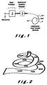
- the sound signals are picked up by a microphone, converted into digital signals, and processed by the signal processor in order to activate different stimulation channels, which stimulate different groups of nerve fibres of the auditory nerve.
- the area where the initialisation of action potentials takes place is referred to as the excitation area.
- the initialisation site of the action potential can be located either in the dendrites, at the site of the cell body, at the level of the axons or any combination.
- the buffer is implemented as a temporal peak hold storage.
- a drawback of the known cochlear implants is that there is no clear distinction between sound processing part and stimulation channels.
- the stimulation strategy i.e. the manner according to which the various stimulation channels are activated, according to the prior art does not take sufficiently into account the patient-dependent data.
- WO-A-98-49775 discloses a partly implanted hearing aid where sound is sorted out on twelve fixed tonotopic channels with each one electrode.
- a cochlear implant is characterised in that said signal processor comprises a stimulation channel configuration unit connected with said storage buffer and provided for configurating stimulation channels in order to create electro-magnetic fields along auditory neural structures, said stimulation channel configuration unit being connected to said electrode contacts and further provided to allocate to each stimulation channel at least two of said electrode contacts, to each stimulation channel there being assigned a memory element provided for storing a waveform pattern and a wave duration according to and during which an intensity value determined on the basis of the stored sampled audio signal value attributed to the considered stimulation channel is applicable to the electrode contacts allocated to the considered stimulation channel, said memory element being further provided for storing a maximum value for said intensity value indicating a maximum field strength for the considered stimulation channel and a first and second field identifier identifying a field spread in a basal and apical direction relative to a position of the stimulation channel.
- the stimulation channel configuration unit makes it possible to establish specific stimulation channel configurations and specific stimulation intensity values and waveforms for each patient and store them.
- a first preferred embodiment of a cochlear implant according to the invention is characterised in that it comprises a stimulation sequence identifier, provided for identifying a set of groups of stimulation channels which are simultaneously stimulatable, the stimulation channels of a same group being selected in order to enable a neural stimulation at neural excitation locations which match with neural excitation locations that would be obtained if the individual stimulation channels of the group would have been stimulated sequentially in time, said stimulation sequence identifier being further provided for cyclically stimulating said groups of stimulating channels. Simultaneous stimulation of several auditory neural structures thus becomes available. In such a manner, a more efficient stimulation strategy can be obtained leading to a better audible result for the patient.
- a second preferred embodiment of a cochlear implant according to the invention is characterised in that it comprises an ordering unit provided to order the groups within the set according to a sequence defining the order according to which the different groups are sequentially stimulated. By arranging the groups, a more efficient use of the stimulation channels is obtained.
- a time frame is assigned to each group of said set in such a manner, that the time frame of the assigned group is at least equal to the waveform duration of the stimulation channel within the considered group having the largest waveform duration.
- the storage buffer of cochlear implant according to the invention such as a cochlear implant is characterised in that said read signal generator is provided for generating read signals asynchronously from said storing into said storage buffer.
- said storage buffer is provided to set a stored sampled signal value to a preset value under control of a read signal after read of the stored audio signal value
- each audio channel unit and said storage buffer are connected to a comparator, said comparator being provided for comparing a sampled audio signal value supplied by an audio channel unit with the stored sampled signal value for that audio channel unit and for generating a writing signal if said supplied sampled audio signal value has a higher absolute signal value than said stored sampled absolute audio signal value, said storage buffer being provided for storing said supplied sampled signal value under control of said writing signal.
- the electrical currents, applied on the electrode surfaces create electrical field gradients along nerve fibres of the auditory nerve or neural structures. Based on the spatial organisation of the individual auditory nerve fibres in the cochlea, electrical fields of different stimulation channels result in activating various groups of nerve fibres. The activated nerve fibres fire action potentials and transmit these to higher auditory centers. The higher auditory centers process the parallel information, which the consciousness center then experiences as auditory information with different pitch sensations, loudness sensation, etc.
- the nerve action potential is an "all or nothing" signal and as such consequently does not contain information.
- the underlying generated time patterns and the places of initialisation determine perception.
- the normal internal cochlear structures such as the Basilar membrane (BM) with the organ of Corti, play a crucial role in the conversion of the sound evoked mechanical movement to action potentials.
- the Basilar membrane performs a (non linear) filtering, as a result of which low-frequency information mainly stimulates the nerve fibres situated in the apical region (at the end) of the cochlea, while highfrequency signals activate the basally located nerve fibres.
- the auditory nerve fibres carry frequency dependent information due to the tonotopic organisation as illustrated in figure 2.
- this frequency-based tonotopy can be imitated by electrically activating electrode surfaces at various places along the nerve fibres.
- the non-linear (NL) behaviour of the BM results in a compression, with a compression factor of 2 to 3 around the region of maximum vibration.
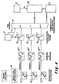
- Figure 3 gives, by means of a flow chart, a schematic example of how the signal processor 2 processes the signals picked up by the input devices. It also gives a schematic representation of the multichannel waveform generator 3 with its R (R ⁇ 1) stimulation channels and, which determines the stimulation strategy. After analog to digital conversion (10), the signal to noise ratio (S/N) of the signal is improved and information reduced by for example taking in account the normal masking curves of the auditory system (11).
- the electrical analog of the acoustic signal is split up into N audio channels.
- Non linear filters which take into account the tonotopic position of the nerve fibres, separate (12) the signal into a sequence of electrical signals.
- the audio channels process further the output signals of the various frequency bands (13), by applying i. a. a compression, possible rectification, filtering, etc., in order to obtain a signal value per audio channel.
- Each audio channel has an output associated with a first sampling unit provided for sampling at an audio channel associated sampling rate the signal output by that channel.
- Sampled values of the output signals of the audio channels are directly linked to the stimulation levels in one or more corresponding stimulation channels.
- the sampled signal values produced by the specific output signal per audio channel are temporarily saved in a data storage buffer (14).
- the way in which this information supplied by audio channels is processed by the waveform generator and passed to its stimulation channels, in order to stimulate various groups of nerve fibres is referred to as stimulation strategy.
- the waveform generator contains both patient-dependent (15) and patient-independent (16) data for processing and controlling the activation of the various stimulation channels.
- Figure 4 shows an example of how the sound signal is split up by the signal processor into N (N ⁇ 1) audio channels and processed. After reduction of the signal, based on auditory masking (20), the sound signal is split up by N non-linear (transmission line) filters 21 into N audio channels. The characteristics of the non-linear filters reflect the properties of the basilar membrane and the active feedback mechanisms, like compression around the characteristic place.
- the compression unit simulates the function performed by the inner-, outer hair cells, etc., while the low-pass filters in each channel simulate the internal hair cell filtering and other physiological effects.
- Each filter 23 is connected to the data storage buffer 24, in which the sampled signal values, produced by the audio channels, are stored.
- the outputs of the audio channels 23 are presented to the data buffer at audio-channel dependent sampling frequencies (fsi) controlled by the first sampling unit 27 associated with the signal processor unit.
- the new presented values are stored in the hold buffer under condition that the absolute value of the stored value is lower than the absolute value of the new sampled available data of the corresponding audio channel.
- a preset value for example a zero or minimum value, is stored in the storage buffer under control of a read signal generated by the waveform, each time after that a sampled signal value is read from the storage buffer 24.
- a new value is supplied by one of the audio channel filters 23 to the storage buffer, that new value is compared by means of a comparator, which is part of the signal processor, to the sampled signal value stored in the storage buffer for the considered audio channel.
- the comparator When the supplied new value has a higher absolute signal value than the stored signal value, the comparator generates a writing signal. The new signal is then stored in the storage buffer under control of the writing signal. If the new value is lower than the stored one, no writing signal is generated and the new value is ignored.
- the storage buffer 24 is linked (by means of a channel-mapping function) to a stimulation channel of the waveform generator 26, which includes stimulation channels to which electrode contacts are attributed by the stimulation-channel-configuration unit.
- the channel-mapping function connects each audio channel to one or more stimulation channels.
- the analog input signal undergoes various processes, performed by the signal processor, in order to generate signal values for each of the stimulation channels to be activated. Since this involves fluctuating signals, these audio channel outputs show a waveform with amplitude maxima and minima.
- the storage buffer has been implemented as follows. Before the signal processor writes the sampled data of an audio channel in the storage buffer, the comparator, connected to the signal generator and the data buffer, performs a comparison between the absolute value of the available sample and the stored absolute value corresponding this audio channel.
- the absolute value saved in the data buffer for the i th audio channel in question (1 ⁇ i ⁇ N) will be compared with the sampled absolute signal value delivered by the audio channel -i. If the i th absolute value saved in the data buffer is higher than or equal to the sampled absolute value delivered by the i th audio channel, then the latter value is not written to the data buffer, and the saved value is maintained. If, on the other hand, the value delivered by the audio channel is higher than the saved i th absolute value, then the sampled value of the i th audio channel is written to the buffer. This comparison is performed for each of the N channels when the first sampling unit of the signal generator gives a new sampled value at one of the audio channels outputs.
- the waveform generator reads the stored values on request from stimulation channels. When reading a stored value from the storage buffer the corresponding stored value is set to a preset value, which could be zero. In this manner, the storage buffer maintains the maximal available sampled data of an audio channel output between successive requests of a stimulation channel. When request signal rate is faster than or equal to the sampling rate the read data follows the sampled data. When request rate is lower than the sampling rate the read data corresponds with the maximum sampled data presented to the storage buffer between successive readings.
- the signal values saved in the storage buffer are read by the waveform generator unit 26 under control of its own sampling unit 28 generating sampling signals fw and which functions totally independent and asynchronously from the sampling unit of the signal processor.
- the storage buffer which temporarily stores values, the reading and writing of the signal values can be performed totally independently and asynchronously between audio channels and stimulation channels, so that the processing of the audio signal is no longer time linked to the stimulation strategy.
- the asynchronous reading and writing, and the storage buffer make it possible to unlink the speech processing from the waveform generator and his stimulation strategy and allows to combine in an easy way different signal processing systems with different stimulation strategies.
- the waveform generator controls the translation of the values stored in the storage buffer 24 to stimulation patterns at the level of the multi-surface-contact electrode.
- the waveform generator unit 26 constructs a series of R stimulation channels, taking into account patient-dependent data, the patient's case history, stimulation history, and the temporal and simultaneous electric field interaction during stimulation, etc..
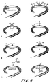
- FIG. 6 illustrates a number of configurations where surface contacts are combined and associated with a stimulation channel.
- one of the electrode contacts is usually placed in a position at a relatively long distance (relative to the distance between one of the contacts in the electrode array and the nerve fibres) from the second electrode contact.
- the electrode contacts are placed closer together along the multi surface electrode array.
- Other configurations are possible, such as radial (6c) and transversal (6d) stimulation configurations, etc. More than 2 contacts can be involved, as an example using three or more contacts a quadrupole configuration can be obtained (6e).
- a stimulation channel can use any combination of electrode contacts, which stimulated together, creates an electric excitation field along the auditory nerve fibres by means of injected currents (electric charges). Electrode contacts associated to a channel are connected with a voltage or current source or grounded to a reference. The individual values of the voltages and currents associated with the contacts of a stimulation channel can be any fraction and polarity relative to the controlling value of this stimulation channel when stimulating. For example figure 6c shows a contact configuration where two side-by-side contacts are connected with current sources with a value of each +1/2 of the controlling value I, while the longitudinal electrode is connected with a current source having a value of a fraction of -1 (inverse polarity) of the controlling value.
- the maximum intensity of the electric excitation field associated with this stimulation channel should be restricted to allow a controlled overlap between the maximum excitation fields associated with nearby stimulation channels while under this condition the amount of neural activation should be of the same strength (obviously depending on neural survival etc.).
- a stimulation channel is addressed by only one controlling value (stimulation amplitude) derived from one audio channel, which is used to determine the intensity and duration of the injected currents at the different contacts involved in this stimulation channel.
- Each stimulation channel possesses its stimulation waveform pattern and waveform duration or time period.
- This waveform controls the instantaneous values of the current sources and or voltage sources associated with the contacts belonging to a stimulation channel. For example to obtain the instantaneous source values for the individual contacts of a stimulation channel, the controlling value of this stimulation channel is multiplied with the instantaneous value of the normalised waveform (max value is 1).
- While stimulating the average injected current through each contact surface of the electrode should go to zero over time.
- One way to obtain this is by selecting charge-balanced waveforms.
- the output signal from the audio channel should be a pure AC signal. If in this case the audio channel output contains a dc component, compensating cycle should be inserted to balance net charge to zero over time.
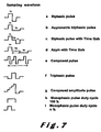
- each waveform is characterised by its shape and time pattern.
- Figure 7 shows different shapes such as : a symmetric biphasic pulse (a), an asymmetric biphasic pulse (b), a symmetric biphasic pulse with a time interval (c), and an asymmetric biphasic pulse with a time interval (d) etc.
- each stimulation channel can have a different waveform and waveform timing.
- the asymmetric pulse can be used to improve the selectivity of bipolar stimulation in one stimulation channel when a charged balanced waveform with time gab can be used to avoid blocking the action potentials in an other channel, etc..
- a stimulation channel When a stimulation channel is stimulating it will trigger action potentials in a group of nerve fibres.
- the initialisation place of those action potentials is called the excitation area.
- the intensity could be so large that the excitation field covers nearly all-accessible auditory nerve fibres. In this case introducing more stimulation channels has hardly any use.
- the spread of excitation field should be limited.
- the excitation field obtained by stimulating this channel with its maximum value is called activation zone of the stimulation channel.
- the activation zone doesn't show necessary one monotonic spatial distribution.
- a stimulation channel should only have access to a population of nerve fibres that do not or only partially overlap with the activation zones of the adjacent (or other) channels.
- the maximum control intensity, associated with a stimulation channel can be derived from the allowed amount of overlap (for example 30%) between the activation zones of this channel and adjacent channels while they all stimulate approximately an equal amount of fibres (if accessible).
- MCL most comfortable level
- the MCL for a sound signal will be depending on the combined stimulation of more stimulation channels, which are activated by more audio channels having acceptable and controllable non linear overlapping filters.
- the way the signal processor and waveform generator handle the incoming signal primarily determines the MCL level for sound signals passing through the signal processor.
- the number of nerve fibres firing an action potential depends on the electric field distribution, the field strength variations, and the condition of the fibres with regards to the membrane noise, the inter-threshold variations, and the stimulation history.
- a fibre When a fibre has fired an action potential, it enters a state in which it is temporarily non-stimulable absolute refractory period between 300 and 500 ⁇ s (hereafter called refractory period). After this period, the stimulation threshold, changes during a period of 1 to 3msec, from an increased value back to the original threshold value. This is called the relative refractory period.
- This relative refractory period is the result of, among other things, the residual opening of the K + channels and the residual inactivation of the Na + channels.
- CAP Compound Action Potential
- the amplitude of the CAP is a first order relative value for the number of fibres being stimulated.
- the number of triggered fibres is related to the stimulation intensity, stimulation history and the individual thresholds of the fibres at that moment.
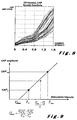
- the function relating the strength of the CAP response (amplitude or integrated surface) as a function of the stimulation intensity of a stimulation channel is called the growth function or I/O function.
- the growth function gives an indication on how the number of recruited fibres increases with the stimulation intensity.
- Low field strengths mainly activate the peripheral endings of the nerves (for example: the dendrites, Ganglion cells (cell bodies) or axons) and lead to the linear increase of the CAP amplitude.
- Higher field strengths trigger the axons of the auditory nerve fibre localised in the center of the modiolus.
- the nerve fibres of higher cochlear turns or adjacent zones lie very close together (especially in the upper turns), so that a small increase in field distribution can result in an enormous increase in the firing of action potentials. This could explain the discontinuity of the I/O function.
- the stimulation of nerve fibres emerging from higher turns (translated perceptually in lower frequencies pitch sensation) when stimulating channels in lower turns is called cross stimulation or cross talk.
- the maximum allowable current in a stimulation channel is determined in such a manner that the activation zone of this stimulation channel only partially overlaps the activation zones (of equal weight) generated by adjacent channels. If a stimulation channel is responsible for cross stimulation the channel should be reconfigured.
- a method for deducting a maximal stimulation intensity of a stimulation channel is described.
- the method described is an objective method and can be used for the computerised determination of maximal stimulation level associated with a stimulating channel.
- the proposed method is based on the following reasoning : when channel n is stimulated with a minimum intensity sufficient to detect any CAP response triggered by a pulse (of any waveform) than the detection of a CAP means that this stimulation intensity allows recruiting a few nerve fibres.
- the amount of fibres recruited under this condition depends on the sensitivity and S/N (signal to noise ratio) of the measuring circuit. Those fibres are the first fibres, which are activatable by means of channel n. In case of poor nerve survival it is quite possible that the same group of excited fibres are also those fibres initiated first by another channel.
- the low intensity stimulating pulse which creates a minimal detectable CAP is called the probe pulse ( I p n ).
- the probe pulse I p n
- the probe pulse determines a maximal stimulation level for each stimulation channel.
- a probe pulse is placed in stimulation channel n+1.
- Channel n is stimulated with a masker pulse 300 to 500usec before the probe pulse.
- the intensity (In) of stimulation channel n is increased so that the CAP response on the probe signal delivered by stimulation channel n+1 is reduced.
- the value I n n+1 is the level of intensity in channel n just enough to mask partially the response in channel n+1.
- a probe signal can be placed in channel n-1 and again a masker in channel n. This results in a value of I n n-1 which is the level of intensity in stimulation channel n just enough to mask partially the response of stimulation channel n-1.
- a stimulation channel n is thus basically determined by three parameters :
- stimulation channel is defined, other parameters can be measured and assigned to the stimulation channel :
- All these parameters are stored in a memory element of a stimulation channel configuration unit 29 connected with the storage buffer 24 and the wave pattern generator.
- the channel configuration unit is provided for defining the stimulation channels i.e. for storing the channels determined as described here before.
- the channel configuration unit at least two electrode contacts are allocated to each stimulation channel.
- the waveform pattern and duration for each channel are stored in the waveform generator 25 connected with unit 29.
- the choice of useful channel configurations based on contact configuration, waveform and waveform duration, is influenced by the minimum current (I offset ) and the achieved relative dynamic range ((Imax-Imin)/Imin).
- Imax limits this dynamic range, which is on his turn related to the restricted overlap between stimulation channels. As a consequence the more channels the lower Imax. With other words the preferable dynamic range is also a function of the amount of stimulation channels involved. Preference is given first to low thresholds and secondly high relative dynamic ranges.
- I offset n (C max n I p n - C p n I max n ) / (C max n - C p n ), where C n / max respectively C n / p represent the CAP amplitude.
- Inserting a control CAP measurement for an intensity corresponding to (I n max + I n p ) /2 allows I offset to be determined more accurately.
- the dynamic range in a stimulation channel is determined on the one hand by the minimum amplitude (I offset ), which did or did not cause action potentials in a small sub-population of the activation zone, and on the other hand by the maximum stimulation amplitude (I max ) in that stimulation channel.
- the dynamic range depends on Imax, which is dependable on the number of stimulation channels.
- the electrical fields of different stimulation channels interact at the level of cochlea due to the conductive features of the medium as for example the electrolytic fluid filled spaces.
- the overall electric field distribution during simultaneous stimulation differs from the sum of the individual field patterns of the same stimulation channels obtained during non-simultaneous stimulation. As a result a subgroup of fibres associated with a stimulation channel is modified depending on simultaneous or not simultaneous stimulation.
- Figure 10 shows the position of the cross section of a multichannel electrode in the Scala Tympani.
- the electrode consists of a silicone substratum with high electrical resistance and individual contacts 5 n-1 , 5n, 5n+1, and a common longitudinal electrode 5L.
- a current is sent from contact 5 n to the longitudinal electrode 5L, it flows from bony structure through the nerve fibre and along the bony structure 8 back to the longitudinal electrode.
- the current path has also a longitudinal component.
- the three-dimensional, nonhomogeneous conductive medium is represented schematically in Figure 11 as a first order approach based on a simplified resistance model. This model is sufficient to clarify the reasoning and terminology.
- Figure 11 shows the conduction path of the longitudinal component presented by the resistance R L and the conduction path, through and along the nerve fibres, presented by R S .
- Ro is a representation of the low resistance path to outside placed contacts. All R S resistances are connected to the longitudinal electrode and there form an equipotential line. Rs includes the interface impedance of the longitudinal electrode.
- the current has to flow as much as possible along the fibres in the vicinity of contact 5 n and thus cause high voltage gradients along the fibres.
- the longitudinal current spread along the electrode is as small as possible. Therefore, the resistance of the longitudinal current-path should be high in respect to the current path resistance towards the longitudinal electrode.
- R L is much larger than R S , most of the current will flow through R S and the stimulation will be very selective. If R L is much smaller than R S , a large current will flow in longitudinal direction, creating higher voltages along the electrode. For other stimulation configuration total different behaviour can be expected.
- Those voltages can be recorded with the implant thanks to incorporated high input impedance amplifiers connectable to the contacts, 5n+1, 5n+2, etc., The voltages directly below the stimulating contacts of a stimulation channel are difficult to measure directly because the exact value of the interface impedance is difficult to know. Those voltages are the driving voltages for the obtained field distribution and we called them V n s (driving voltage contact n).
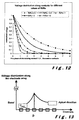
- the voltage distribution along the contacts 5 1 ... 5 n is determined by the R L /R S ratio as illustrated in figure 12.
- This figure shows five curves (for different R L /R S ratio) as a function of distance relative to the stimulating contact.
- the contacts shown are those localised in the apical direction of the stimulating contact 5n. 0 is place of the stimulating contact, 1 is contact 5n+1 etc.
- the model gives, as a first approximation, a symmetrical result. If stimulating towards an outside contact then the curve could be highly asymmetrical due to different current paths in apical and basal direction.
- the curves are normalised so that the voltage V n s below stimulation contact 5n+0 is equal to 1 Volt.
- d decay parameter and x is the number of contact places in respect to the stimulation place.
- the decay parameter can be derived from internal measurements.
- the purpose of the automatic registration of the decay constants d and the interpolated internal control voltages at maximal stimulation intensity of the stimulation channel is to enable to correct the stimulation intensity during simultaneous stimulation and select stimulation channels which can be grouped together for simultaneous stimulation.
- Figure 13 shows a schematic course of voltage variations along the electrode when for example stimulation channel P is activated with a current I producing a driving voltage V S .
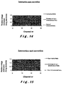
- Figure 14 shows the voltage distribution result, from the model with a large decay parameter 3, when stimulating two channels simultaneous or not. In this example channel ten and fourteen are stimulated in phase. The lowest curve represents the envelope of the two distributions when stimulated sequentially in time and as such don't interfere. In figure 14 the highest curve represents the voltage distribution in the model along the contacts when stimulated simultaneously.
- peak values related to the places of channel ten and fourteen are increased due to interaction. This should be avoided as it perturbs the stimulation and consequently the audible result. Also the voltage distribution between the peaks is increased which could result (also depending on field gradient changes) in stimulating nerve fibres allocated to in between channels. During simultaneous stimulation the increase of the field strength around the peaks of channel ten and fourteen can be cancelled by reducing the input stimulation levels of channel ten and fourteen taking in account the decay parameters. The result is shown in figure 14 by the dotted line. The peak now matches the envelope of the non-simultaneous fields. The area between the peaks is still showing higher voltages compared with the non-simultaneous envelope.
- Table 1 gives a first order relation between the internally measured decay value and the minimal contact distance along electrodes for channels, which can be activated simultaneous (with or without input compensation).
- the first and second column give the limits for d (d is average ( d ) d of the first channel and d of the other channel in the other direction).
- the third column gives the distance between the simultaneous stimulating stimulation channels in terms of number of contacts (#) between the nearest associated contacts of both channels. Decay parameter d # .3 +2 .3 .8 +3 .8 1.5 +4 1.5 2.5 +5 2.5 4 +6 4 5.7 +7 5.7 8.5 +8 8.5 10 +9
- the two channels must be 6 or more contacts apart for simultaneous stimulation.
- the decay factor needs to be ⁇ .3.
- this table limits the choice of channels that can be stimulated simultaneously.
- the decay value depends strongly on the localisation of the electrode. Increasing RL is obtained by reducing the volume of low conductive electrolytic fluid between the contacts. Placing contacts as near as possible towards the basilar membrane or inner wall can do this.
- the stimulation strategy can incorporate a so-called "neural repair” function that takes into account the nerve fibres absolute and relative refractory period.
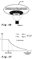
- the channel n has an activation zone represented by the set V n , in accordance with the intensity I n max .
- the channel n is stimulated with amplitude I1.
- the corresponding recruitment zone is represented by Z1. Due to the stochastic threshold variations (due to membrane noise) of the nerve fibres in time, not all fibres in zone Z1 will fire an action potential. Those fibres situated in the center of the excitation zone will usually be activated, since the voltage fields there greatly exceed the threshold values at that location.
- next stimulation amplitude in channel n at moment T2 is larger than the previous one, nerve fibres from a larger excitation zone Z will be recruited. In this case the stimulation channel is activated.
- the recruitment zone is smaller (see Z2) and is situated in the recruitment zone Z1.
- the fibres in this zone are to a large extent activated by the previous pulse. In other words, they are in their absolute or relative refractory period, dependent on the time difference between T1 and T2. If the stimulus interval T2-T1 is smaller than the absolute refractory period T AR , the number of fibres reacting to the stimulus will be relatively small. In this case the pulse does not stimulate.
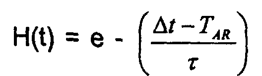
- a neural-repair function H ( ⁇ t) is introduced as shown in figure 17, with At being the inter-stimulus time.
- the value of the function for a stimulation interval smaller than T AR is equal to 1. Subsequently the function drops over a period of 0.5 to 3 ms.
- the illustrated function is an exponential decaying curve for stimulus interval time ⁇ t higher than > Tar. For example : exp -( ⁇ t- Tar)/ ⁇
- the parameter ⁇ is a channel-programmable time constant with a value between 0.5 and a few (e.g. 3) ms..
- a true representation of the sound at the neural level requires an electrical stimulation that accurately follows the spectro-temporal characteristics of the sound.
- the temporal characteristics such as "phase information"
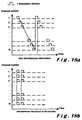
- the stimulation strategy can select two extreme situations for sending the information to the nerve fibres. All stimulation channels are activated successively and this is repeated cyclically. This is known as the Continuous Interleaved Strategy (CIS). Or all channels are stimulated simultaneously, and this is repeated, an example is SAS.
- CIS Continuous Interleaved Strategy
- Figure 18a illustrates a situation with non-simultaneous stimulation and figure 18b with simultaneous stimulation.
- the drawback of CIS is that the stimulation speed per channel decreases as the number of channels increases. For example, if the stimulation duration per pulse is 100 ⁇ s and the number of channels is 50, then the maximum stimulation frequency per channel will be 200Hz. This is not compatible with the desire to achieve the highest possible stimulation speed per channel in order to carry over the temporal information in a sufficiently accurate manner.
- conflict situations can occur, e.g. one or more defined channels can use the same contact, although the waveforms and timing of the channels differ.
- An additional disadvantage is the risk of high power consumption peaks when all channels are activated simultaneously.
- a compromise between CIS and total simultaneous stimulation is combining the channels in various groups.
- the stimulation channels put together in one group are stimulated simultaneously. All channels are divided once or more over different groups.
- the groups are stimulated sequentially one after the other.
- the cochlear implant according to the present invention comprises an ordering unit provided to order groups of stimulation channels according to a sequence defining the order according to which the different groups are sequentially stimulated.
- the ordering unit comprises a group-stimulation sequence table representing which stimulation channels will be stimulated simultaneously and in which order the groups will be stimulated in. Table 2 shows an example.
- Channel nr involved > Group1 Time: ⁇ T1 Group2 Time duration: ⁇ T2 Group q Time: ⁇ Tq Stim-chan1 Yes Yes Yes Stim-chan2 Yes Stim-chan3 Yes Stim-chan4 Yes Stim-chan n (n can be much larger than available contacts very large) Yes Yes
- the content of such a stimulation sequence table is saved in the waveform generator unit.
- ⁇ T1 group1 is stimulated composed of stimulation-channels 1, and 4 together (the waveform-timings of channel 1 and 4 are not necessary equal to the time duration of group1).
- ⁇ T2 channels of group 2 are stimulated etc..
- Group1, group2, etc. to group q are stimulated successively. Criteria will now be provided on how to construct a group :
- a group contains all possible stimulation channels with following restriction :
- a stimulation channel could belong to both group “a” and group “b”, as long as it does not cause a conflict with the other channels in the group.
- a group If a group is becoming too large (due to the physical limitations of the implant, such as excessive power peaks, etc.), it can be divided into 2 or more subgroups, which are then placed in time one after the other.
- Each group has its own programmable duration, which is minimum as long as the maximum of any waveform duration of stimulation-channels belonging to this group.
- This collection of groups forms a cycle called stimulation sequence, and this cycle is repeated again and again.
- the order of placing of the different groups in the cycle is such that the averaged time difference (calculated across the whole sequence) between the stimulation of adjacent channels is maximal to reduce temporal neural effects, which could result from the overlap of the excitation fields of adjacent channels.
- the amplitude values in the storage buffer have to be transformed into stimulation intensities within the dynamic range of the stimulation channel.
- each stimulation channel has its own conversion table or monotonic increasing conversion function, as shown in figure 19.
- A is the amplitude value coming from the storage buffer.
- a min is a programmable amplitude value depending on the compression in the audio channel.
- a max is the maximum amplitude value.
- I offset and I max are the minimum and maximum current for this stimulation channel.
- the maximum value in this audio channel (depending on the signal processor) is linked to I max of the stimulation channel.
- the function between A and I can have a linear relation, or can be linked by a compression or expansion curve.
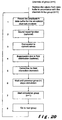
- Figure 20 shows an example of a flow diagram for stimulation, which is repeated successively.
- group N is stimulating, preparations are made for the stimulation of the next group N+1.
Landscapes
- Health & Medical Sciences (AREA)
- Otolaryngology (AREA)
- Engineering & Computer Science (AREA)
- Biomedical Technology (AREA)
- Nuclear Medicine, Radiotherapy & Molecular Imaging (AREA)
- Radiology & Medical Imaging (AREA)
- Life Sciences & Earth Sciences (AREA)
- Animal Behavior & Ethology (AREA)
- General Health & Medical Sciences (AREA)
- Public Health (AREA)
- Veterinary Medicine (AREA)
- Electrotherapy Devices (AREA)
- Non-Silver Salt Photosensitive Materials And Non-Silver Salt Photography (AREA)
- Diaphragms For Electromechanical Transducers (AREA)
- Crystals, And After-Treatments Of Crystals (AREA)
- Time-Division Multiplex Systems (AREA)
Claims (8)
- Cochlea-Implantat, umfassend M (M>1) Elektrodenkontakte und einen Signalprozessor mit einer Eingabe zum Empfang von Schallsignalen, wobei der genannte Signalprozessor einen Satz von N-Schallkanaleinheiten (21) aufweist, die zum Anlegen einer Umsetzung der genannten Schallsignale nach einer Frequenz bezogenen tonotopischen Aufteilung bereitgestellt werden und wobei jede Schallkanaleinheit ferner zur Bildung von Schallsignalwerten durch das Anlegen einer Frequenz bezogenen Filterung der genannten umgesetzten Schallsignale bereitgestellt wird, wobei der Signalprozessor ferner eine Auswahleinheit (27) umfasst, die zum Erzeugen einer Schallsignaleinheit abhängigen Auswahlfrequenz (af) für jede Schallkanaleinheit bereitgestellt wird, wobei jede Schallsignaleinheit einen Ausgang aufweist, der an der Dateneingabe eines Speicherpuffers (24) angeschlossen ist, welcher zum Empfang der genannten Schallsignalwerte, die an der genannten Schallkanaleinheit abhängig von der Auswahlfrequenz ausgewählt ist, und zum vorübergehenden Speichern der genannten Auswahlschallsignalwerte bereitgestellt ist, wobei der genannte Signalprozessor eine Stimulationskanal-Konfigurationseinheit (29) umfasst, die an dem genannten Speicherpuffer angeschlossen ist und zur Konfiguration von Stimulationskanälen bereitgestellt wird, um elektromagnetische Felder entlang der Gehör- und Nervenstrukturen zu generieren, wobei die genannte Stimulationskanal-Konfigurationseinheit an den genannten Elektrodenkontakten angeschlossen ist und ferner bereitgestellt ist, um jedem Stimulationskanal wenigstens zwei der genannten Elektrodenkontakte zuzuordnen, wobei jedem Stimulationskanal dort ein Datenspeicherelement beigeordnet ist, das zum Speichern eines Wellenformmusters und einer Wellendauer bereitgestellt wird, gemäß welchem und während welcher ein Intensitätswert, der auf der Basis der gespeicherten, ausgewählten Schallsignalwerte festgestellt wird, die den in Betracht kommenden Stimulationskanälen zugeordnet wird, auf die Elektrodenkontakte angelegt wird, die dem in Betracht kommenden Stimulationskanal zugeteilt sind, wobei das genannte Speicherelement ferner zum Speichern eines Maximalwertes für den genannten Intensitätswert bereitgestellt wird, der eine maximale Feldstärke des in Betracht kommenden Stimulationskanals und einen ersten und zweiten Feldidentifikator zur Identifizierung eines Felds bezeichnet, das in basaler und apikaler Richtung relativ zu einer Position der Elektrodenkontakte des in Betracht kommenden Stimulationskanal ausgebreitet ist.
- Cochlea-Implantat nach Anspruch 1, dadurch gekennzeichnet, dass es einen Stimulationssequenzidentifikator umfasst, der zur Identifizierung eines Satzes von Gruppen von Stimulationskanälen umfasst, die gleichzeitig stimuliert werden können, wobei die Stimulationskanäle ausgewählt aus derselben Gruppe sind, um eine Nervenstimulierung an Nervenreizstellen zu ermöglichen, die den Nervenreizstellen entsprechen, welche erhalten würden, wenn die einzelnen Stimulationskanäle der Gruppe zeitfolgerichtig stimuliert worden wären, wobei der genannte Stimulationssequenzidentifikator ferner zur periodischen Stimulierung der genannten Gruppen von Stimulierungskanälen bereitgestellt ist.
- Cochlea-Implantat nach Anspruch 2, dadurch gekennzeichnet, dass ein Satz von Gruppen sämtliche Stimulationskanäle umfasst, wobei jede Gruppe des genannten Satzes sämtliche Stimulationskanäle umfasst, die die genannte Entsprechung erfüllen.
- Cochlea-Implantat nach Anspruch 2 oder 3, dadurch gekennzeichnet, dass es eine Befehlseinheit umfasst, die zum Befehlen der Gruppen innerhalb des Satzes gemäß der Sequenzdefinierung des Befehls, gemäß welcher die verschiedenen Gruppen folgerichtig stimuliert sind, bereitgestellt ist.
- Cochlea-Implantat nach einem der Ansprüche 2 bis 4, dadurch gekennzeichnet, dass jeder Gruppe des genannten Satzes in solcher Weise ein Zeitrahmen beigeordnet wird, dass der Zeitrahmen der beigeordneten Gruppe wenigstens gleich der Wellenformdauer des Stimulationskanals innerhalb der in Betracht kommenden Gruppe mit der größten Welfenformdauer ist.
- Cochlea-Implantat nach einem der Ansprüche 2 bis 5, dadurch gekennzeichnet, dass das genannte Speicherelement ferner zum Speichern einer Nerven-Instandsetzungsfunktion H(t), wobei H(t) = 1 für t < TAR steht, wobei TAR die Gesamtrefraktärphase unddarstellt, wobei Δt der Stimulusintervall und τ eine Stimulationskanal-Zeitkonstante ist.
- Cochlea-Implantat nach einem der Ansprüche 1 bis 6 und wobei der genannte Speicherpuffer an einem Wellenformgenerator angeschlossen ist, der zum Bilden wenigstens eines Stimulationskanals bereitgestellt ist, wobei der genannte Wellenformgenerator und der genannte Speicherpuffer an einem Signallesegenerator angeschlossen ist, der zum Generieren der Lesesignale bereitgestellt ist, um das Lesen der gespeicherten, ausgewählten Tonsignalwerte von dem genannten Speicherpuffer zu ermöglichen und wobei der genannte Wellenformgenerator zum Abrufen unter der Steuerung der genannten Lesesignale der genannten, ausgewählten Signalwerte jeder Schallkanaleinheit von dem genannten Speicherpuffer zum Generieren, basierend auf den genannten, ausgewählten Schallsignalwerten bereitgestellt ist, wobei die Wellenformen eine Zeitdauer und ein Wellenmuster aufweisen, wobei der genannte Wellenformgenerator an den Elektrodenkontakten des genannten Cochlea-Implantats angeschlossen ist und zur Stimulierung durch die genannten Wellenformen der genannten Stimulationskanäle bereitgestellt ist, dadurch gekennzeichnet, dass der genannte Lesesignalgenerator zum Generieren von Lesesignalen asynchron vom genannten Speichern in den genannten Speicherpuffer bereitgestellt ist.
- Cochiea-Implantat nach Anspruch 1, dadurch gekennzeichnet, dass der genannte Speicherpuffer bereitgestellt ist, um einen gespeicherten, ausgewählten Signalwert auf den derzeitigen Wert unter der Steuerung eines Lesesignals nach dem Lesen des gespeicherten Schallsignalwertes einzustellen, wobei jede Schallkanaleinheit und der genannte Speicherpuffer an einem Komparator angeschlossen sind, wobei der genannte Komparator zum Vergleichen eines ausgewählten Schallsignalwertes, der an eine Schallkanaleinheit übertragen wird, mit dem gespeicherten, ausgewählten Signalwert dieser Schallkanaleinheit und zum Generieren eines Schreibsignals, falls der genannte übertragene, ausgewählte Tonsignalwert einen höheren, absoluten Signalwert aufweist, als der genannte gespeicherte, ausgewählte, absolute Tonsignalwert, bereitgestellt ist, wobei der genannte Speicherpuffer zum Speichern der genannten übertragenen, ausgewählten Signalwerte unter der Steuerung des genannten Schreibsignals bereitgestellt ist.
Applications Claiming Priority (3)
| Application Number | Priority Date | Filing Date | Title |
|---|---|---|---|
| BE9900621 | 1999-09-16 | ||
| BE9900621 | 1999-09-16 | ||
| PCT/BE2000/000109 WO2001019304A1 (en) | 1999-09-16 | 2000-09-18 | Cochlear implant |
Publications (2)
| Publication Number | Publication Date |
|---|---|
| EP1216014A1 EP1216014A1 (de) | 2002-06-26 |
| EP1216014B1 true EP1216014B1 (de) | 2005-04-20 |
Family
ID=3892093
Family Applications (1)
| Application Number | Title | Priority Date | Filing Date |
|---|---|---|---|
| EP00960240A Expired - Lifetime EP1216014B1 (de) | 1999-09-16 | 2000-09-18 | Cochlea-implantat |
Country Status (7)
| Country | Link |
|---|---|
| US (1) | US6778858B1 (de) |
| EP (1) | EP1216014B1 (de) |
| AT (1) | ATE293418T1 (de) |
| AU (1) | AU7262600A (de) |
| CA (1) | CA2381725C (de) |
| DE (1) | DE60019621T2 (de) |
| WO (1) | WO2001019304A1 (de) |
Families Citing this family (71)
| Publication number | Priority date | Publication date | Assignee | Title |
|---|---|---|---|---|
| US8260430B2 (en) * | 2010-07-01 | 2012-09-04 | Cochlear Limited | Stimulation channel selection for a stimulating medical device |
| US7917224B2 (en) | 1999-07-21 | 2011-03-29 | Med-El Elektromedizinische Geraete Gmbh | Simultaneous stimulation for low power consumption |
| AU775268B2 (en) | 1999-08-26 | 2004-07-29 | Med-El Elektromedizinische Gerate Gmbh | Electrical nerve stimulation based on channel specific sampling sequences |
| US8165686B2 (en) | 1999-08-26 | 2012-04-24 | Med-El Elektromedizinische Geraete Gmbh | Simultaneous intracochlear stimulation |
| US6728578B1 (en) | 2000-06-01 | 2004-04-27 | Advanced Bionics Corporation | Envelope-based amplitude mapping for cochlear implant stimulus |
| US9008786B2 (en) * | 2000-08-21 | 2015-04-14 | Cochlear Limited | Determining stimulation signals for neural stimulation |
| US7822478B2 (en) * | 2000-08-21 | 2010-10-26 | Cochlear Limited | Compressed neural coding |
| AUPQ952800A0 (en) | 2000-08-21 | 2000-09-14 | Cochlear Limited | Power efficient electrical stimulation |
| US8285382B2 (en) | 2000-08-21 | 2012-10-09 | Cochlear Limited | Determining stimulation signals for neural stimulation |
| AU2002312636B2 (en) * | 2001-05-24 | 2007-08-30 | Hearworks Pty Limited | A peak-derived timing stimulation strategy for a multi-channel cochlear implant |
| AUPR604801A0 (en) | 2001-06-29 | 2001-07-26 | Cochlear Limited | Multi-electrode cochlear implant system with distributed electronics |
| US7107101B1 (en) | 2001-08-17 | 2006-09-12 | Advanced Bionics Corporation | Bionic ear programming system |
| US7043303B1 (en) * | 2002-08-30 | 2006-05-09 | Advanced Bionics Corporation | Enhanced methods for determining iso-loudness contours for fitting cochlear implant sound processors |
| WO2004021363A1 (en) * | 2002-09-02 | 2004-03-11 | Cochlear Limited | Method and apparatus for envelope detection and enhancement of pitch cue of audio signals |
| AU2003901538A0 (en) * | 2003-03-28 | 2003-05-01 | Cochlear Limited | Maxima search method for sensed signals |
| US20070239227A1 (en) * | 2003-08-15 | 2007-10-11 | Fridman Gene Y | Frequency modulated stimulation strategy for cochlear implant system |
| US7702396B2 (en) * | 2003-11-21 | 2010-04-20 | Advanced Bionics, Llc | Optimizing pitch allocation in a cochlear implant |
| US8036753B2 (en) * | 2004-01-09 | 2011-10-11 | Cochlear Limited | Stimulation mode for cochlear implant speech coding |
| US8577473B2 (en) | 2004-03-08 | 2013-11-05 | Med-El Elektromedizinische Geraete Gmbh | Cochlear implant stimulation with low frequency channel privilege |
| AU2005245218B2 (en) * | 2004-03-08 | 2010-06-24 | Med-El Elektromedizinische Geraete Gmbh | Electrical stimulation of the acoustic nerve based on selected groups |
| US7941223B2 (en) * | 2004-03-08 | 2011-05-10 | Med-El Elektromedizinische Geraete Gmbh | Cochlear implant stimulation with variable number of electrodes |
| US8660658B2 (en) | 2004-05-05 | 2014-02-25 | Advanced Bionics Ag | Speech processor cases |
| US8068914B1 (en) | 2004-05-05 | 2011-11-29 | Advanced Bionics, Llc | Speech processor cases |
| US7421298B2 (en) * | 2004-09-07 | 2008-09-02 | Cochlear Limited | Multiple channel-electrode mapping |
| US7522961B2 (en) * | 2004-11-17 | 2009-04-21 | Advanced Bionics, Llc | Inner hair cell stimulation model for the use by an intra-cochlear implant |
| US7242985B1 (en) | 2004-12-03 | 2007-07-10 | Advanced Bionics Corporation | Outer hair cell stimulation model for the use by an intra—cochlear implant |
| US7715912B2 (en) * | 2005-04-13 | 2010-05-11 | Intelect Medical, Inc. | System and method for providing a waveform for stimulating biological tissue |
| US9339650B2 (en) | 2005-04-13 | 2016-05-17 | The Cleveland Clinic Foundation | Systems and methods for neuromodulation using pre-recorded waveforms |
| US9211408B2 (en) | 2005-04-13 | 2015-12-15 | The Cleveland Clinic Foundation | System and method for neuromodulation using composite patterns of stimulation or waveforms |
| US8082033B2 (en) * | 2005-04-13 | 2011-12-20 | The Cleveland Clinic Foundation | System and method for providing a waveform for stimulating biological tissue |
| US8369958B2 (en) * | 2005-05-19 | 2013-02-05 | Cochlear Limited | Independent and concurrent processing multiple audio input signals in a prosthetic hearing implant |
| US20090222064A1 (en) * | 2005-07-08 | 2009-09-03 | Advanced Bionics, Llc | Autonomous Autoprogram Cochlear Implant |
| WO2007019498A2 (en) * | 2005-08-08 | 2007-02-15 | University Of Florida Research Foundation, Inc. | Device and methods for biphasis pulse signal coding |
| US9265933B2 (en) | 2005-09-08 | 2016-02-23 | Massachusetts Eye And Ear Infirmary | Cochlear implants containing biological cells and uses thereof |
| US7729775B1 (en) | 2006-03-21 | 2010-06-01 | Advanced Bionics, Llc | Spectral contrast enhancement in a cochlear implant speech processor |
| US8818517B2 (en) * | 2006-05-05 | 2014-08-26 | Advanced Bionics Ag | Information processing and storage in a cochlear stimulation system |
| US8000797B1 (en) * | 2006-06-07 | 2011-08-16 | Advanced Bionics, Llc | Systems and methods for providing neural stimulation with an asynchronous stochastic strategy |
| US7864968B2 (en) * | 2006-09-25 | 2011-01-04 | Advanced Bionics, Llc | Auditory front end customization |
| US7995771B1 (en) | 2006-09-25 | 2011-08-09 | Advanced Bionics, Llc | Beamforming microphone system |
| US8019430B2 (en) * | 2007-03-21 | 2011-09-13 | Cochlear Limited | Stimulating auditory nerve fibers to provide pitch representation |
| US9795794B2 (en) * | 2007-08-10 | 2017-10-24 | Med-El Elektromedizinische Geraete Gmbh | Pulse width adaptation for inductive links |
| JP2011500143A (ja) * | 2007-10-09 | 2011-01-06 | イムセラ・メディカル・インコーポレーテッド | 選択的刺激のための装置、システム、及び方法 |
| CA2704623C (en) | 2007-11-09 | 2015-03-17 | Med-El Elektromedizinische Geraete Gmbh | Pulsatile cochlear implant stimulation strategy |
| US8840654B2 (en) * | 2011-07-22 | 2014-09-23 | Lockheed Martin Corporation | Cochlear implant using optical stimulation with encoded information designed to limit heating effects |
| US20090306745A1 (en) * | 2008-03-31 | 2009-12-10 | Cochlear Limited | Electrode assembly for delivering longitudinal and radial stimulation |
| EP2285444B1 (de) | 2008-04-22 | 2016-11-02 | MED-EL Elektromedizinische Geräte GmbH | Tonotopische implantat-stimulation |
| US20090287277A1 (en) * | 2008-05-19 | 2009-11-19 | Otologics, Llc | Implantable neurostimulation electrode interface |
| US20100069997A1 (en) * | 2008-09-16 | 2010-03-18 | Otologics, Llc | Neurostimulation apparatus |
| EP2358426A4 (de) | 2008-12-08 | 2012-12-05 | Med El Elektromed Geraete Gmbh | Verfahren zum einsetzen eines cochleaimplantats mit patienten-feedback |
| EP2380363B1 (de) | 2009-01-20 | 2015-09-30 | MED-EL Elektromedizinische Geräte GmbH | Hochpräzise, tonotope und periodische kodierung mit erweiterter harmonischer auflösung |
| AU2010208258B2 (en) | 2009-01-28 | 2013-03-14 | Med-El Elektromedizinische Geraete Gmbh | Channel specific gain control including lateral suppression |
| US8954158B2 (en) * | 2009-02-05 | 2015-02-10 | Cochlear Limited | Multi-electrode channel configurations |
| US8688222B2 (en) | 2009-02-05 | 2014-04-01 | Cochlear Limited | Stimulus timing for a stimulating medical device |
| AU2010210544B2 (en) | 2009-02-06 | 2012-12-13 | Med-El Elektromedizinische Geraete Gmbh | Phase triggered envelope sampler |
| WO2010111320A2 (en) | 2009-03-24 | 2010-09-30 | Med-El Elektromedizinische Geraete Gmbh | Musical fitting of cochlear implants |
| US8019429B2 (en) * | 2009-03-24 | 2011-09-13 | Med-El Elektromedizinische Geraete Gmbh | Carrier and envelope triggered cochlear stimulation |
| US9044588B2 (en) * | 2009-04-16 | 2015-06-02 | Cochlear Limited | Reference electrode apparatus and method for neurostimulation implants |
| US20100318167A1 (en) * | 2009-04-17 | 2010-12-16 | Otologics, Llc | Neurostimulation electrode array and method of manufacture |
| WO2010138911A1 (en) | 2009-05-29 | 2010-12-02 | Otologics, Llc | Implantable auditory stimulation system and method with offset implanted microphones |
| US9031661B2 (en) | 2010-05-18 | 2015-05-12 | Cochlear Limited | Multi-electrode channel configurations for a hearing prosthesis |
| PL2616142T3 (pl) * | 2010-09-15 | 2019-04-30 | Med El Elektromedizinische Geraete Gmbh | Sposób i układ do przyspieszonego dopasowywania implantów ślimakowych w oparciu o rozkład prądu |
| EP2632538B1 (de) | 2010-10-30 | 2015-04-22 | Advanced Bionics AG | Systeme für multi-monopolare stromsteuerung in einem hörprothesensystem |
| US8515540B2 (en) | 2011-02-24 | 2013-08-20 | Cochlear Limited | Feedthrough having a non-linear conductor |
| CN106215322B (zh) * | 2011-05-13 | 2019-01-22 | Med-El电气医疗器械有限公司 | 具有通道交互补偿的同时刺激的最佳模型常数 |
| US9227063B2 (en) | 2011-11-30 | 2016-01-05 | Advanced Bionics Ag | Methods and systems for lowering a pitch sensation as perceived by a cochlear implant patient |
| US20130245717A1 (en) * | 2012-03-15 | 2013-09-19 | Med-El Elektromedizinische Geraete Gmbh | Using Alternative Stimulus Waveforms To Improve Pitch Percepts Elicited With Cochlear Implant Systems |
| USD693008S1 (en) | 2013-03-09 | 2013-11-05 | Advanced Bionics Ag | Sound processor enclosure exterior |
| US11071869B2 (en) | 2016-02-24 | 2021-07-27 | Cochlear Limited | Implantable device having removable portion |
| US10743114B2 (en) * | 2016-11-22 | 2020-08-11 | Cochlear Limited | Dynamic stimulus resolution adaption |
| CN111175606B (zh) * | 2020-02-17 | 2025-12-05 | 浙江诺尔康神经电子科技股份有限公司 | 一种人工耳蜗多通道刺激脉冲半波检测系统及方法 |
| CN111462764B (zh) * | 2020-06-22 | 2020-09-25 | 腾讯科技(深圳)有限公司 | 音频编码方法、装置、计算机可读存储介质及设备 |
Family Cites Families (5)
| Publication number | Priority date | Publication date | Assignee | Title |
|---|---|---|---|---|
| US4532930A (en) * | 1983-04-11 | 1985-08-06 | Commonwealth Of Australia, Dept. Of Science & Technology | Cochlear implant system for an auditory prosthesis |
| WO1997009012A1 (en) * | 1995-09-05 | 1997-03-13 | Cochlear Pty. Limited | Percutaneous multiplexer for therapeutic systems |
| BE1010268A3 (nl) * | 1996-04-17 | 1998-04-07 | Antwerp Bionic Systems Nv | Auditieve prothese. |
| FR2749462B1 (fr) | 1996-06-04 | 1998-07-24 | Ela Medical Sa | Dispositif autonome, notamment dispositif medical implantable actif et, son programmateur externe a transmission synchrone |
| DE69817555T2 (de) | 1997-05-01 | 2004-06-17 | Med-El Elektromedizinische Geräte GmbH | Verfahren und gerät für eine digitale filterbank mit geringem stromverbrauch |
-
2000
- 2000-09-18 AT AT00960240T patent/ATE293418T1/de not_active IP Right Cessation
- 2000-09-18 WO PCT/BE2000/000109 patent/WO2001019304A1/en not_active Ceased
- 2000-09-18 EP EP00960240A patent/EP1216014B1/de not_active Expired - Lifetime
- 2000-09-18 CA CA002381725A patent/CA2381725C/en not_active Expired - Fee Related
- 2000-09-18 AU AU72626/00A patent/AU7262600A/en not_active Abandoned
- 2000-09-18 DE DE60019621T patent/DE60019621T2/de not_active Expired - Lifetime
- 2000-09-18 US US10/088,194 patent/US6778858B1/en not_active Expired - Lifetime
Also Published As
| Publication number | Publication date |
|---|---|
| ATE293418T1 (de) | 2005-05-15 |
| DE60019621T2 (de) | 2006-03-02 |
| CA2381725A1 (en) | 2001-03-22 |
| US6778858B1 (en) | 2004-08-17 |
| CA2381725C (en) | 2008-01-22 |
| AU7262600A (en) | 2001-04-17 |
| EP1216014A1 (de) | 2002-06-26 |
| WO2001019304A1 (en) | 2001-03-22 |
| DE60019621D1 (de) | 2005-05-25 |
Similar Documents
| Publication | Publication Date | Title |
|---|---|---|
| CA2381725C (en) | Cochlear implant | |
| EP1874399B1 (de) | Fokussierte stimulation in einer medizinischen stimulationsvorrichtung | |
| White et al. | Multichannel cochlear implants: Channel interactions and processor design | |
| US7076308B1 (en) | Cochlear implant and simplified method of fitting same | |
| US8948877B2 (en) | Cochlear implant stimulation with low frequency channel privilege | |
| EP2393550B1 (de) | Konfiguration für multielektrodenkanäle | |
| US9227059B2 (en) | Methods and apparatus for cochlear implant signal processing | |
| US7941223B2 (en) | Cochlear implant stimulation with variable number of electrodes | |
| US7899547B1 (en) | Level-dependent stimulation methods and systems | |
| US7171261B1 (en) | Forward masking method for estimating neural response | |
| RU2440156C2 (ru) | Кохлеарная протезирующая система, система стимуляции и машиночитаемый носитель информации (варианты) | |
| EP0867102A1 (de) | Rückkoppelungssystem zur elektrodenspannungensteuerung in einem cochlearen stimulator und dgl. | |
| US20060052841A1 (en) | Multiple channel-electrode mapping | |
| WO2009010870A2 (en) | Using interaction to measure neural excitation | |
| US7317944B1 (en) | System and method for using a multi-contact electrode to stimulate the cochlear nerve or other body tissue | |
| WO2021053045A1 (en) | Cochlear implant fitting based on neuronal status | |
| EP1702494A1 (de) | Verzögerte stimulation in gehörprotesen | |
| Macherey et al. | Forward-masking patterns produced by symmetric and asymmetric pulse shapes in electric hearing | |
| Shannon | A model of temporal integration and forward masking for electrical stimulation of the auditory nerve | |
| US20100010570A1 (en) | Auditory prosthesis | |
| AU2004298073B2 (en) | Delayed stimulation in auditory prostheses |
Legal Events
| Date | Code | Title | Description |
|---|---|---|---|
| PUAI | Public reference made under article 153(3) epc to a published international application that has entered the european phase |
Free format text: ORIGINAL CODE: 0009012 |
|
| 17P | Request for examination filed |
Effective date: 20020416 |
|
| AK | Designated contracting states |
Kind code of ref document: A1 Designated state(s): AT BE CH CY DE DK ES FI FR GB GR IE IT LI LU MC NL PT SE |
|
| AX | Request for extension of the european patent |
Free format text: AL;LT;LV;MK;RO;SI |
|
| 17Q | First examination report despatched |
Effective date: 20040130 |
|
| GRAP | Despatch of communication of intention to grant a patent |
Free format text: ORIGINAL CODE: EPIDOSNIGR1 |
|
| GRAS | Grant fee paid |
Free format text: ORIGINAL CODE: EPIDOSNIGR3 |
|
| GRAA | (expected) grant |
Free format text: ORIGINAL CODE: 0009210 |
|
| AK | Designated contracting states |
Kind code of ref document: B1 Designated state(s): AT BE CH CY DE DK ES FI FR GB GR IE IT LI LU MC NL PT SE |
|
| PG25 | Lapsed in a contracting state [announced via postgrant information from national office to epo] |
Ref country code: FI Free format text: LAPSE BECAUSE OF FAILURE TO SUBMIT A TRANSLATION OF THE DESCRIPTION OR TO PAY THE FEE WITHIN THE PRESCRIBED TIME-LIMIT Effective date: 20050420 Ref country code: LI Free format text: LAPSE BECAUSE OF FAILURE TO SUBMIT A TRANSLATION OF THE DESCRIPTION OR TO PAY THE FEE WITHIN THE PRESCRIBED TIME-LIMIT Effective date: 20050420 Ref country code: ES Free format text: LAPSE BECAUSE OF FAILURE TO SUBMIT A TRANSLATION OF THE DESCRIPTION OR TO PAY THE FEE WITHIN THE PRESCRIBED TIME-LIMIT Effective date: 20050420 Ref country code: AT Free format text: LAPSE BECAUSE OF FAILURE TO SUBMIT A TRANSLATION OF THE DESCRIPTION OR TO PAY THE FEE WITHIN THE PRESCRIBED TIME-LIMIT Effective date: 20050420 Ref country code: CH Free format text: LAPSE BECAUSE OF FAILURE TO SUBMIT A TRANSLATION OF THE DESCRIPTION OR TO PAY THE FEE WITHIN THE PRESCRIBED TIME-LIMIT Effective date: 20050420 |
|
| RAP1 | Party data changed (applicant data changed or rights of an application transferred) |
Owner name: ADVANCED BIONICS N.V. |
|
| REG | Reference to a national code |
Ref country code: GB Ref legal event code: FG4D |
|
| REG | Reference to a national code |
Ref country code: CH Ref legal event code: EP |
|
| REG | Reference to a national code |
Ref country code: IE Ref legal event code: FG4D |
|
| REF | Corresponds to: |
Ref document number: 60019621 Country of ref document: DE Date of ref document: 20050525 Kind code of ref document: P |
|
| PG25 | Lapsed in a contracting state [announced via postgrant information from national office to epo] |
Ref country code: GR Free format text: LAPSE BECAUSE OF FAILURE TO SUBMIT A TRANSLATION OF THE DESCRIPTION OR TO PAY THE FEE WITHIN THE PRESCRIBED TIME-LIMIT Effective date: 20050720 Ref country code: SE Free format text: LAPSE BECAUSE OF FAILURE TO SUBMIT A TRANSLATION OF THE DESCRIPTION OR TO PAY THE FEE WITHIN THE PRESCRIBED TIME-LIMIT Effective date: 20050720 Ref country code: DK Free format text: LAPSE BECAUSE OF FAILURE TO SUBMIT A TRANSLATION OF THE DESCRIPTION OR TO PAY THE FEE WITHIN THE PRESCRIBED TIME-LIMIT Effective date: 20050720 |
|
| PG25 | Lapsed in a contracting state [announced via postgrant information from national office to epo] |
Ref country code: CY Free format text: LAPSE BECAUSE OF FAILURE TO SUBMIT A TRANSLATION OF THE DESCRIPTION OR TO PAY THE FEE WITHIN THE PRESCRIBED TIME-LIMIT Effective date: 20050918 |
|
| PG25 | Lapsed in a contracting state [announced via postgrant information from national office to epo] |
Ref country code: IE Free format text: LAPSE BECAUSE OF NON-PAYMENT OF DUE FEES Effective date: 20050919 |
|
| PG25 | Lapsed in a contracting state [announced via postgrant information from national office to epo] |
Ref country code: PT Free format text: LAPSE BECAUSE OF FAILURE TO SUBMIT A TRANSLATION OF THE DESCRIPTION OR TO PAY THE FEE WITHIN THE PRESCRIBED TIME-LIMIT Effective date: 20050920 |
|
| PG25 | Lapsed in a contracting state [announced via postgrant information from national office to epo] |
Ref country code: MC Free format text: LAPSE BECAUSE OF NON-PAYMENT OF DUE FEES Effective date: 20050930 Ref country code: LU Free format text: LAPSE BECAUSE OF NON-PAYMENT OF DUE FEES Effective date: 20050930 |
|
| REG | Reference to a national code |
Ref country code: CH Ref legal event code: PL |
|
| PLBE | No opposition filed within time limit |
Free format text: ORIGINAL CODE: 0009261 |
|
| STAA | Information on the status of an ep patent application or granted ep patent |
Free format text: STATUS: NO OPPOSITION FILED WITHIN TIME LIMIT |
|
| ET | Fr: translation filed | ||
| 26N | No opposition filed |
Effective date: 20060123 |
|
| REG | Reference to a national code |
Ref country code: IE Ref legal event code: MM4A |
|
| PGFP | Annual fee paid to national office [announced via postgrant information from national office to epo] |
Ref country code: IT Payment date: 20090729 Year of fee payment: 10 |
|
| PGFP | Annual fee paid to national office [announced via postgrant information from national office to epo] |
Ref country code: NL Payment date: 20100909 Year of fee payment: 11 |
|
| PGFP | Annual fee paid to national office [announced via postgrant information from national office to epo] |
Ref country code: BE Payment date: 20101012 Year of fee payment: 11 |
|
| PG25 | Lapsed in a contracting state [announced via postgrant information from national office to epo] |
Ref country code: IT Free format text: LAPSE BECAUSE OF NON-PAYMENT OF DUE FEES Effective date: 20100918 |
|
| BERE | Be: lapsed |
Owner name: *ADVANCED BIONICS N.V. Effective date: 20110930 |
|
| REG | Reference to a national code |
Ref country code: NL Ref legal event code: V1 Effective date: 20120401 |
|
| PG25 | Lapsed in a contracting state [announced via postgrant information from national office to epo] |
Ref country code: BE Free format text: LAPSE BECAUSE OF NON-PAYMENT OF DUE FEES Effective date: 20110930 |
|
| PG25 | Lapsed in a contracting state [announced via postgrant information from national office to epo] |
Ref country code: NL Free format text: LAPSE BECAUSE OF NON-PAYMENT OF DUE FEES Effective date: 20120401 |
|
| REG | Reference to a national code |
Ref country code: FR Ref legal event code: PLFP Year of fee payment: 17 |
|
| PGFP | Annual fee paid to national office [announced via postgrant information from national office to epo] |
Ref country code: GB Payment date: 20160927 Year of fee payment: 17 |
|
| PGFP | Annual fee paid to national office [announced via postgrant information from national office to epo] |
Ref country code: FR Payment date: 20160926 Year of fee payment: 17 |
|
| PGFP | Annual fee paid to national office [announced via postgrant information from national office to epo] |
Ref country code: DE Payment date: 20160928 Year of fee payment: 17 |
|
| REG | Reference to a national code |
Ref country code: DE Ref legal event code: R119 Ref document number: 60019621 Country of ref document: DE |
|
| GBPC | Gb: european patent ceased through non-payment of renewal fee |
Effective date: 20170918 |
|
| REG | Reference to a national code |
Ref country code: FR Ref legal event code: ST Effective date: 20180531 |
|
| PG25 | Lapsed in a contracting state [announced via postgrant information from national office to epo] |
Ref country code: DE Free format text: LAPSE BECAUSE OF NON-PAYMENT OF DUE FEES Effective date: 20180404 Ref country code: GB Free format text: LAPSE BECAUSE OF NON-PAYMENT OF DUE FEES Effective date: 20170918 |
|
| PG25 | Lapsed in a contracting state [announced via postgrant information from national office to epo] |
Ref country code: FR Free format text: LAPSE BECAUSE OF NON-PAYMENT OF DUE FEES Effective date: 20171002 |