EP1216151B1 - Computergesteuerte etikettiervorrichtung in abhängigkeit der position - Google Patents
Computergesteuerte etikettiervorrichtung in abhängigkeit der position Download PDFInfo
- Publication number
- EP1216151B1 EP1216151B1 EP20000950263 EP00950263A EP1216151B1 EP 1216151 B1 EP1216151 B1 EP 1216151B1 EP 20000950263 EP20000950263 EP 20000950263 EP 00950263 A EP00950263 A EP 00950263A EP 1216151 B1 EP1216151 B1 EP 1216151B1
- Authority
- EP
- European Patent Office
- Prior art keywords
- label
- container
- microprocessor
- encoder
- machine base
- Prior art date
- Legal status (The legal status is an assumption and is not a legal conclusion. Google has not performed a legal analysis and makes no representation as to the accuracy of the status listed.)
- Expired - Lifetime
Links
Images








Classifications
-
- B—PERFORMING OPERATIONS; TRANSPORTING
- B65—CONVEYING; PACKING; STORING; HANDLING THIN OR FILAMENTARY MATERIAL
- B65C—LABELLING OR TAGGING MACHINES, APPARATUS, OR PROCESSES
- B65C9/00—Details of labelling machines or apparatus
- B65C9/40—Controls; Safety devices
- B65C9/42—Label feed control
-
- B—PERFORMING OPERATIONS; TRANSPORTING
- B65—CONVEYING; PACKING; STORING; HANDLING THIN OR FILAMENTARY MATERIAL
- B65C—LABELLING OR TAGGING MACHINES, APPARATUS, OR PROCESSES
- B65C3/00—Labelling other than flat surfaces
- B65C3/06—Affixing labels to short rigid containers
- B65C3/08—Affixing labels to short rigid containers to container bodies
-
- B—PERFORMING OPERATIONS; TRANSPORTING
- B65—CONVEYING; PACKING; STORING; HANDLING THIN OR FILAMENTARY MATERIAL
- B65C—LABELLING OR TAGGING MACHINES, APPARATUS, OR PROCESSES
- B65C9/00—Details of labelling machines or apparatus
- B65C9/08—Label feeding
- B65C9/18—Label feeding from strips, e.g. from rolls
- B65C9/1865—Label feeding from strips, e.g. from rolls the labels adhering on a backing strip
-
- G—PHYSICS
- G05—CONTROLLING; REGULATING
- G05B—CONTROL OR REGULATING SYSTEMS IN GENERAL; FUNCTIONAL ELEMENTS OF SUCH SYSTEMS; MONITORING OR TESTING ARRANGEMENTS FOR SUCH SYSTEMS OR ELEMENTS
- G05B19/00—Program-control systems
- G05B19/02—Program-control systems electric
- G05B19/18—Numerical control [NC], i.e. automatically operating machines, in particular machine tools, e.g. in a manufacturing environment, so as to execute positioning, movement or co-ordinated operations by means of program data in numerical form
- G05B19/414—Structure of the control system, e.g. common controller or multiprocessor systems, interface to servo, programmable interface controller
-
- G—PHYSICS
- G05—CONTROLLING; REGULATING
- G05B—CONTROL OR REGULATING SYSTEMS IN GENERAL; FUNCTIONAL ELEMENTS OF SUCH SYSTEMS; MONITORING OR TESTING ARRANGEMENTS FOR SUCH SYSTEMS OR ELEMENTS
- G05B2219/00—Program-control systems
- G05B2219/30—Nc systems
- G05B2219/34—Director, elements to supervisory
- G05B2219/34322—Intitialize execution program at reference position on workpiece
-
- G—PHYSICS
- G05—CONTROLLING; REGULATING
- G05B—CONTROL OR REGULATING SYSTEMS IN GENERAL; FUNCTIONAL ELEMENTS OF SUCH SYSTEMS; MONITORING OR TESTING ARRANGEMENTS FOR SUCH SYSTEMS OR ELEMENTS
- G05B2219/00—Program-control systems
- G05B2219/30—Nc systems
- G05B2219/37—Measurements
- G05B2219/37002—Absence, detect absence, presence or correct position of workpiece
-
- G—PHYSICS
- G05—CONTROLLING; REGULATING
- G05B—CONTROL OR REGULATING SYSTEMS IN GENERAL; FUNCTIONAL ELEMENTS OF SUCH SYSTEMS; MONITORING OR TESTING ARRANGEMENTS FOR SUCH SYSTEMS OR ELEMENTS
- G05B2219/00—Program-control systems
- G05B2219/30—Nc systems
- G05B2219/50—Machine tool, machine tool null till machine tool work handling
- G05B2219/50049—Control machine as function of position, angle of workpiece
-
- G—PHYSICS
- G05—CONTROLLING; REGULATING
- G05B—CONTROL OR REGULATING SYSTEMS IN GENERAL; FUNCTIONAL ELEMENTS OF SUCH SYSTEMS; MONITORING OR TESTING ARRANGEMENTS FOR SUCH SYSTEMS OR ELEMENTS
- G05B2219/00—Program-control systems
- G05B2219/30—Nc systems
- G05B2219/50—Machine tool, machine tool null till machine tool work handling
- G05B2219/50234—Synchronize two spindles, axis, electronic transmission, line shafting
-
- Y—GENERAL TAGGING OF NEW TECHNOLOGICAL DEVELOPMENTS; GENERAL TAGGING OF CROSS-SECTIONAL TECHNOLOGIES SPANNING OVER SEVERAL SECTIONS OF THE IPC; TECHNICAL SUBJECTS COVERED BY FORMER USPC CROSS-REFERENCE ART COLLECTIONS [XRACs] AND DIGESTS
- Y10—TECHNICAL SUBJECTS COVERED BY FORMER USPC
- Y10T—TECHNICAL SUBJECTS COVERED BY FORMER US CLASSIFICATION
- Y10T156/00—Adhesive bonding and miscellaneous chemical manufacture
- Y10T156/17—Surface bonding means and/or assemblymeans with work feeding or handling means
- Y10T156/1702—For plural parts or plural areas of single part
- Y10T156/1705—Lamina transferred to base from adhered flexible web or sheet type carrier
- Y10T156/1707—Discrete spaced laminae on adhered carrier
-
- Y—GENERAL TAGGING OF NEW TECHNOLOGICAL DEVELOPMENTS; GENERAL TAGGING OF CROSS-SECTIONAL TECHNOLOGIES SPANNING OVER SEVERAL SECTIONS OF THE IPC; TECHNICAL SUBJECTS COVERED BY FORMER USPC CROSS-REFERENCE ART COLLECTIONS [XRACs] AND DIGESTS
- Y10—TECHNICAL SUBJECTS COVERED BY FORMER USPC
- Y10T—TECHNICAL SUBJECTS COVERED BY FORMER US CLASSIFICATION
- Y10T156/00—Adhesive bonding and miscellaneous chemical manufacture
- Y10T156/17—Surface bonding means and/or assemblymeans with work feeding or handling means
- Y10T156/1702—For plural parts or plural areas of single part
- Y10T156/1705—Lamina transferred to base from adhered flexible web or sheet type carrier
- Y10T156/1707—Discrete spaced laminae on adhered carrier
- Y10T156/171—Means serially presenting discrete base articles or separate portions of a single article
-
- Y—GENERAL TAGGING OF NEW TECHNOLOGICAL DEVELOPMENTS; GENERAL TAGGING OF CROSS-SECTIONAL TECHNOLOGIES SPANNING OVER SEVERAL SECTIONS OF THE IPC; TECHNICAL SUBJECTS COVERED BY FORMER USPC CROSS-REFERENCE ART COLLECTIONS [XRACs] AND DIGESTS
- Y10—TECHNICAL SUBJECTS COVERED BY FORMER USPC
- Y10T—TECHNICAL SUBJECTS COVERED BY FORMER US CLASSIFICATION
- Y10T156/00—Adhesive bonding and miscellaneous chemical manufacture
- Y10T156/17—Surface bonding means and/or assemblymeans with work feeding or handling means
- Y10T156/1702—For plural parts or plural areas of single part
- Y10T156/1744—Means bringing discrete articles into assembled relationship
- Y10T156/1768—Means simultaneously conveying plural articles from a single source and serially presenting them to an assembly station
- Y10T156/1771—Turret or rotary drum-type conveyor
Definitions
- the present invention relates to control of container labeling equipment. More specifically, the invention relates to procedures and apparatus for accurately applying labels, such as pressure sensitive labels, to containers, utilizing continual monitoring of the absolute positions of the container and label in order to correctly apply the labels at high container speeds.
- labels such as pressure sensitive labels
- Currently-used label applicator systems frequently use a type of motion control system referred to as "velocity slaving". Such systems start a predefined move of the label initiated by a stimulus and wherein the velocity of the label is dictated by the ratio-metric velocity of the container. The feedback as to the container velocity is generated by a main container-handling portion of the machine. Additionally, the end point for the application of the labels carried by a carrier web, to a particular container may be advanced or retarded based on a registration stimulus incorporated into the system.
- Another significant limitation of the velocity slaved labeling process is due to the fact that it is linear in nature. Such linearity is manifested by the direct speed match between the master encoder and predictable linear acceleration and deceleration ramps controlling movement of the labels. By utilizing the linear properties of the velocity profile, basically a trapezoid, the label placement position is derived. Such devices are limited by the fact that very complex requirements may be needed to match the label velocity to the container surface velocity but the master encoder still runs at a constant rate thereby ruling out complex moves. One situation where such applicators fail is where the length of the material available to accelerate to the surface velocity of the container is too short.
- US-A-5,650,037 describes a thermal ink transfer decorating apparatus for transferring graphical and decorative images from a moving web to moving articles such as containers.
- WO-A-96/40559 describes a computer controlled labeling machine for applying labels to an article.
- a further important aspect involves the intimate coupling of the slave motion control system, which controls a label carrier web's position, to the position of the master feedback device, i.e., an encoder or a resolver, and thus to the position of the containers.
- the master feedback device i.e., an encoder or a resolver
- an ability to offset the commanded position of the container (or other specific object on a container) is provided.
- This offset in the form of an electronic signal received from a sensing device, identifies the absolute location of the container or object such as a previously applied label, which, in effect, produces an absolute position independent of the main container handling portion of the machine but which is relative to each container or object on the container.
- a high precision position control results in the ability to provide very complex motion even at speeds of 750 labels per minute.
- the motion of the label-carrying web is not linear with respect to the position of the master, i.e., the container handler.
- the use of position slaving, in accordance with the invention overcomes this limitation.
- a mathematical algorithm is provided for each specific container configuration or shape to allow for the ability to generate complex move profiles.
- the position of the label carrier web is related mathematically to the position of each container as it travels and possibly rotates past the label application head.
- a method of labeling containers which includes providing a container handling machine such as conveyor in the case of an inline labeling machine, and a rotary bottle table in the case of a rotary labeling machine, for successively transporting containers past a label application station.
- the container handling machine i.e., "machine base” has an associated position signaling device such as a rotary encoder for providing data in electronic form identifying the position of the machine.
- the encoder makes one revolution each time the container handling machine translates a distance equal to the center-to center distance between successive containers.
- the encoder could be set to make more than one revolution per machine pitch, if desired.
- a label applicator is driven by a servomotor with said servomotor being controlled by a microprocessor-based slave position motion controller.
- the label applicator includes an electronic signal generator identifying the motion controller position of each successive label dispensed by the label applicator.
- a machine base position control or identifying microprocessor is operatively connected to the label applicator's motion controlling microprocessor and to the machine base encoder.
- An electronic signal generator identifying the physical position of the container or object such as a previously applied label on the container surface is operatively connected to the position control microprocessor.
- the machine base position control microprocessor generates signals to the label applicator's motion controlling microprocessor that relates the position of the container to be labeled.
- the label applicator servomotor contains an associated position identifying device such as an encoder that provides electronic data to the motion control microprocessor that relates to servo motor position and velocity.
- the motion control microprocessor is operatively connected to a label applicator servo amplifier, the servo motor encoder and to the machine base encoder.
- the label applicator servo amplifier is operatively connected and provides power to the label applicator servomotor.
- the motion control microprocessor generates a move profile for each successive label, using mathematical algorithms, and electronically controls the label applicator servo amplifier to vary the torque applied by the servomotor.
- Electronic feedback signals from the servo motor encoder and machine encoder to the motion control microprocessor provide the electronic position and velocity feedback data needed to control the torque applied by the servo amplifier and servo motor.
- such signals are continually generated and processed at a rate of at least once each 125 th microsecond.
- a host microprocessor generates a pitch based electronic shift register that contains information on the labeling processes that need to be performed on a container.
- the host microprocessor provides the labeling commands and is operatively connected to a label position motion control microprocessor.
- a pressure sensitive label application system consists of equipment that applies pressure sensitive labels which are coated with a adhesive, successively, to the surfaces of a series of containers.
- a system of this invention is capable of supporting at least from 1 to 4 label application stations, thus applying from one to four separate labels to one container or similar object, in independent mode, and two combinations of the same label on 4 stations in redundant mode.
- the most general configuration 20 of this system is shown in Figure 1.
- This two label application station machine 20 is defined as a synchronous "rotary" machine because the position of each container is governed by the position of the machine.
- Containers moving down a conveyor 26 are captured and spaced apart by infeed screw 24.
- Infeed screw 24 is driven by a gear train that originates at the bottle table 32.
- an electronic sensing device i.e., a "bottle present sensor” 25.
- the infeed screw 24 will transfer containers in a synchronous fashion and in mechanical coordination with pockets in an infeed star 28.
- the infeed star 28 is geared to the bottle table 32. As the infeed star 28 rotates, each container will travel along the radius of the centering guide 30 to transfer, in mechanical coordination, to a bottle support plate 34.
- the bottle table 32 rotates on its main bearing 44, containers on bottle plates 34 are carried to the first label application station 36 ("head #1").
- the application station 36 is to apply a label
- a label will be applied while the container continues to travel with the bottle table 32.
- the container continues through an outside brush station 37 and an inside brush station 39.
- the brush stations 37 and 39 wipe the label down onto the surface of the container.
- the bottle table 32 contains a mechanical cam track with cam followers attached to the bottle plates. The cam track will cause the bottle plates to rotate during label wipe down through the brush stations.
- the containers continue to travel to application station 38 ("head #2").
- the container continues onto discharge star 40.
- the discharge star 40 which is geared to the bottle table 32
- the container is captured by the centering guide 30 to be transferred synchronously to the discharge star 40.
- the container will travel along the radius of the centering guide 30 to transfer from the discharge star 40 to a discharge conveyor 22.
- encoder 274 which serves as a position feedback device.
- Such devices generally include encoders and resolvers, as will be recognized by those skilled in the art.
- Such devices are, for convenience and by way of example, rather than by way of limitation, referred to herein as "encoders.”
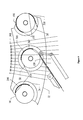
- a second general configuration 49 of a labeling system is shown in Figure 2.
- This machine 49 is defined as a non-synchronous "inline" machine. Such inline machines are considered non-synchronous because the position of the container is random with respect to known pre-defined positions of the machine.
- the container-handling portion of machine 49 consists of a conveyor 50 and, usually, container-engaging timing belts 51, which are not part of this invention.
- the machine base encoder 53 is geared to the conveyor drive motor 54 and its gearbox 52 and conveyor 50 , such that the encoder 53 will make at least 1 revolution per container.
- Containers travel down the conveyor 50 in the direction indicated by the arrow 56 near the infeed of the machine 49.
- the timing belts 51 capture the containers 58 upon entry to the machine.
- the timing belts 51 turn traveling generally in the same direction as conveyor 50, and maintain position control of the containers.
- the timing belts 51 may be used to manipulate the containers 58, for example, by rotating them, if required in a particular labeling sequence.
- Containers 58 continue to travel into the machine 49 where the leading edge of each container 58 is detected by an electronic sensing device, which is usually a photoelectric cell, i.e., the bottle present sensor 60 and its retroreflector 62.
- the electronic bottle present sensor 60 will electronically identify the position of the container with respect to the machine base encoder 53. Such identification or "position stamping" of the leading edge of the container establishes the physical position of the container within the machine 49.
- an electronic sensing device decects the leading edge of the container 58 and identifies or "position stamps" its location with respect to the machine encoder 53.
- This new position stamp enables correction of position error of the container 58 prior to labeling. Such errors may be caused by irregularities in the container configuration or dimensions, positioning on the machine base, etc.
- the container will then continue on to the label application station 68 ("head #1").
- the application station 68 is to apply a label as a particular container that passes the application station, a label will be applied while the container continues to travel with the conveyor 50.
- the container continues through the brush station 70 which wipes the label down onto the surface of the container 58 as the container rotates across a brush.
- each label application head 68 or 78 applies the same label, with one head being active and the other in standby. If label application 78 ("head #2") is active, while label application head 68 is inactive, the sequence of operation remains the same .
- the label application head 68 or 78 is responsible for the motion of the web 80 and the transfer of the leading edge of a label 306 to the surface of a container.
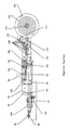
- web 79 which carries labels 80 enters a push-pull actuator assembly 82 shown in detail in Figure 4c.
- the web 79 with labels 80 passes around a first idler roller 180 and then proceeds around the smooth "push" capstan roller 160.
- the web 79 with labels 80 leaves the push-pull unit and proceeds to spender arm assembly 81.
- the spender arm assembly 81 of a type know to the art is composed of the spender arm mounting bracket 88, spender arm pivot bracket 90, spender arm pivot groove 92, spender arm upper rod 94, and lower rod 95, spender plate 96, spender plate foot 98, web guide assembly 100, and sensor mounting assembly 102.
- the web 79 with labels 80 will pass across the front of the spender arm to and around the edge of the spender plate 96 thereby causing the labels to separate from the web, in know fashion.
- the web 79 without labels will then continue on to and around another idler roller 180 to the "pull" capstan 158.
- the web continues around the "pull" capstan 158 and continues on to the rewind dancer assembly rollers 108. After the web passes through the rewind dancer assembly 109, the web is rewound onto the rewind capstan 130, as a roll 146.
- the rewind dancer is constructed of a series of rollers. One set of rollers are stationary, with the other set mounted to a dancer arm 134 connected to a pivot shaft that is in turn connected to the rewind proportioning disk 110.
- An electronic signal generator 112 monitors the position of the proportioning disk 110. As material leaves the push-pull assembly 84, the dancer arm 134 moves toward an open position to provide for storage of the material due to the force applied by the spring tension device 111. The electronic signal generator 112 monitors the position change of the proportioning disk 110 and outputs an analog electronic signal to the motor drive 114 that feeds power to the DC unwind motor 116.
- the DC unwind motor 116 drives its gearbox 118 through a right angle shaft adapter 120 to drive the rewind capstan 130 and disk 126.
- the dancer arm 134 will move towards a closed position thus causing the electronic signal generator 112 to reduce the analog signal to the rewind drive 114, thus reducing the speed of the motor 116.
- the smooth "push” capstan 160 is attached to its drive gear 156 ( Figure 4b), with the knurled “pull” capstan 158 being also attached to a drive gear 154.
- the servomotor 150 through the servomotor drive gear 152 drives the gears 160 and 156.
- Rubber coated nip rollers 164 and 162 have eccentric shafts that are actuated by the nip pressure actuation levers 166 and 170.
- Spring 172 applies tension to the "push” capstan nip pressure actuator lever 170. This actuation causes the rubber coated nip roller 164 to apply pressure to the smooth "push” capstan 160.
- Spring 168 applies tension to the "pull” capstan nip pressure actuation lever 166. This actuation causes the rubber coated nip roller 162 to apply pressure to the knurled "pull” capstan 158.
- the circumference of the smooth capstan 160 is slightly less than the circumference of the knurled capstan 158.
- the drive gears for the capstans 160 and 158 are the same size.
- the mismatch in circumference between the two capstans causes the web to acquire tension.
- Web tension is dictated by the frictional component of the web 80 to the surface of the smooth capstan 160.
- the applied pressure of the rubber nip roller 164 dictates the quantity of friction to the smooth capstan 160.
- the web tension controls the peel angle of the label as it leaves the web, as the web is pulled around the sharp edge of the spend
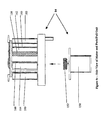
- the unwind station shown in Figures 5a and 5b is a stand-alone system that functions to provide web material 79 with labels 80 to the label application head 68 or 78 from a roll of label material.
- the unwind station also provides an inertia buffer between the high acceleration web drive assembly 84, Figures 4a, 4b and 4c, and the large inertial load of the material reel 204.
- a supply roll of unused label material 204 is mounted onto the unwind hub 202 and fixtured between the unwind disks 206.
- the web material 79 with labels 80 is pulled from roll 204 by the nip 212 created by the nip roller assemble 214 and a rubber coated unwind drive roller 216.
- the unwind drive roller 216 is connected to the DC motor 219 and controlled by the electronic signaling device 220. As the label application head dispenses labels, the web inertia buffer gravity loop bobbin 220 will move up as web material is pulled from the buffer zone 218. An electronic signaling device 222 signals the motor 219 to turn on. The motor 219 drives the unwind drive roller 216 which in turn pulls web material across the web guide idler roller 208 and from the material roll 204. As the unwind drive roller 216 pulls material from the material roll 204 into the buffer zone 218, the bobbin 220 will move down until the electronic sensing device 222 detects the bobbin 220 thus turning the motor 219 off. The web tension brushes 234 and 240 apply tension to the web 80 to stabilize the web path.
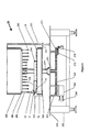
- the machine base 20 shown, in elevation in Figure 6, is responsible for the flow of containers and their positions with respect to the application heads 36 and 38.
- a rotary encoder 274 geared to the bottle table 258 through main bull gear 260.
- the main bull gear 260 is driven by main drive gear 262, which in turn is driven by gearbox 264 and the main drive motor 266.
- the master encoder 274 is geared to the machine such that it makes one revolution per container. This is accomplished by the correct selection of intermediary encoder gears 271 and 272.
- the master encoder 274 provides feedback to the computer control systems on each containers physical location on the machine.
- Bull gear 260 drives main bearing shaft 261, which in turn drives the rotating components including the bottle table assembly 258 and carrier assembly 286.
- the main bearing housing 254 supports the rotating components and the non-rotating bottle table cam housing assembly 268.
- the containers in the machine are fixtured by the bottle plates 270 and the centering bells 282 which are connected to the spring loaded centering head 284, that is affixed to the carrier assembly 286.
- cam segments in the bottle table cam housing assembly 268 turn the containers to the correct kinematic positions that relate to the needs of the appropriate process.
- the kinematics include presentations and motion for labeling, label wipe down and other process such as inspection or coding.
- Figure 6 includes examples of the wipe down brush stations including the outside brush station mount 269, the outside brush mount assembly 292, the wipe down brush 290 and the inside brush mount 298, with its associated inside wipe down brush 296.
- the support columns 255 affix the non-rotating portions of the machine head 280 and cam carrier housing 256.
- the brush station bearing 294 is affixed to the outside of the machine base table plate 250 and affix the inside brush stations to the non-rotation machine base.
- the table plate support assembly 252 supports the machine table plate 250.
- the correlation of the encoder 274 to the machine base position is defined as the machine master axis.
- the centerline distance between two containers is defined as one pitch.
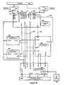
- Label application control is accomplished with a multiprocessor computer controlled servo system or motion control system. See Figure 17.
- the motion control processor 520 with its corresponding servo amplifier 524 and servomotor 526 are responsible for the actual motion of the label carrying web 80.
- Computer host processor 536 is responsible for the system background tasks, internal machine process shift register and process rules.
- the container tracking processor 528 is responsible for all machine position controls.
- the bottle present sensor 538 signals the container tracking processor 528 that a container is entering the machine.
- the container tracking processor 528 electronically notifies the computer host processor 536 that a container is present.
- the computer host processor 536 enters a valid container into the internal labeling process shift register.
- the machine continues to rotate the z axis pulse of the master encoder 522 providing electronic position signals to the container tracking processor 528, indicates the beginning of the next pitch cycle.
- the container tracking processor 528 will electronically indicate to the computer host processor 536 that a new pitch has started.
- the computer host processor 536 will increment the internal labeling process shift register.
- the labeling process shift register pitch increment process will continue as the container moves through the machine, until the container reaches the label application head or a container/label position correction sensor 534.
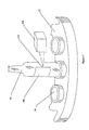
- the machine incorporates the use of the optional container/label position correction sensor 308, the position of a surface artifact such as a surface embossment on a container or a previously applied label 306 ( Figure 7), may be used as a position reference for a container 58 which is, thus, independent of the container fixtures 34 of the bottle table 32.
- the electronic signal generated by the container/label position correction sensor 308 provides a position locating electronic signal or "stamp" to the container tracking processor 528 which relates to the exact position of the master encoder 274.
- the stamped position of the master encoder 274 is then electronically compared to a preset application parameter in the container tracking processor 528, which specifies the predicted position of the tracked artifact thus generating a label contact point position offset.
- the label contact point position offset is turn used to edit, electronically, the preset label contact point position parameter which dictates the position on the container to which the label is to be applied.
- the computer host processor 536 indicates electronically to the container tracking processor 528 that a container is to be labeled. As the container enters the labeling zone the container tracking processor 528 electronically signals the motion control processor 520 to begin the labeling process.
- the correlation of the motion control system's internal position feedback that is the servo loop closed around the web drive motor feedback 411, with respect to the label carrying web position feedback 410, is defined as the labeling axis.
- the leading edge of each label must applied to a precise position on the associated container and the velocity of the label during application must match the surface velocity of the container.
- the motion profile is required to prepare itself for the next labeling process as well as to correct for any registration error which may have occurred.
- the means of performing the label application motion is through a position slaved move profile. That is, a move profile where the labeling axis position is based on the position of the master axis encoder 400, of the machine base.
- the servo loop of the labeling axis 412 is also a closed position loop with the label's leading edge used as a registration mark where and in feedback is provided by electronic signaling device 414, the registration sensor, which electronically position stamps the labeling axis position at the point of the registration mark.
- This correction can only be allowed to occur when the actual labeling process is not being performed in order to reduce label-to-container surface velocity mismatch which would result from attempted position correction during label application.
- the process of motion control referred to as position slaving relies fundamentally on the use of a master axis and a slave axis.
- the master axis indicated by encoder 274 provides feedback for computing the commanded position of the servo system of the slave or labeling axis.
- the slave axis is assigned a corresponding position.
- the master feedback relates to the position of the machine base and is mechanically geared such that the feedback period is one machine pitch in length. Note that the period is measured in distance instead of time since this is not a time based motion controller, but a position based controller.
- a position slaved servo loop can be described, in general, by means of a block diagram of the basic components of the servo loop.
- the main reference bench mark that dictates the motion is the position of the machine base encoder 400.
- This position is signaled to processor 528 which utilizes a profile-generating algorithm 402 such that the desired position of the label web is directly related to the machine base position based on the algorithm's mathematical equation.
- the resulting motion profile ideally can be generated and updated continually if the processing power of the servo controller is sufficient. If this is not possible, the motion profile could also be generated, only upon receiving new setup information relating to the geometry of the label, web, container, or machine which is stored in a look up table.
- the position slaved servo system would then generate its motion profile by referencing the look up table and utilizing the master feedback as an index to the table. Then, only the servo loop update and registration correction algorithm calculation are performed in real time.
- the remaining blocks in the diagram Figure 10, describe a general type of high performance positioning servo system.
- the system utilizes the torque controlled servo amplifier 404 closed around a proportional, integral, derivative (PID) servo loop 406 utilizing velocity and acceleration feedforward terms 408 to essentially eliminate following error in the system.
- PID proportional, integral, derivative
- the position slaved motion profile illustrated graphically in Figures 11 and 12, will implement a piecewise continuous function comprised of a minimum of three separate functions. These functions are represented by mathematical equations wherein the mathematical expression is a function of master feedback counts. The three basic portions of the illustrated complete function are:
- the function denoted as f s (1) 422 or 434 is the region of acceleration of the web.
- the function denoted as f s (2) 424 or 436 represents a region of the curve where the labeling process is occurring.
- the illustrated curve in this case is a constant velocity function. This is not, however, generally the case for applications with complicated container geometry or special labeling requirements.
- the function denoted as f s (3) 426 or 438 is the region of deceleration of the web.
- the example shown utilized a sinusoidal profile generator in both the position (Figure 11) and velocity ( Figure 12) domain of the profile.
- f s (4) 428 or 440 The function denoted as f s (4) 428 or 440 is optional as shown. Function f s (4) 428 or 440 would be used to back the web up to allow for more web material to be made available in the event that the servo system does not have the acceleration capabilities to achieve the surface velocity of the container within the constraints of the label application travel distance.
- the label application travel distance is comprised of the label length plus the gap between adjacent labels on the web.
- a situation requiring f s (4) presently occurs on pressure sensitive labeling machines where the application requires short labels on high surface velocity machines. Note that these functions can not be performed on prior art velocity slaved system.
- the example shown utilizes a sinusoidal profile generation utilizing a half period in the position domain as shown in Figure 11.
- Region f s (4) 428, 440 or f s (5) 430, 442 will also be utilized as the regions where registration error correction is accomplished. This is necessary to account for the outer position loop 410, Figure 10 to be closed around the web material itself. It is desirable to perform the correction here since the label application has been completed and the system is simply preparing for the next application.
- a motion control processor 520 that incorporates the use of microprocessors capable of performing math intensive functions at a very high rate is provided.
- microprocessors capable of performing math intensive functions at a very high rate.
- This technology includes digital signal processors such as the advanced or modified Harvard architecture processor.
- microprocessor technology continues to advance, the nature of the microprocessor is not directly a part of the invention except in so far as the ability to process and calculate complex mathematical equations that relate to the position of a label to be applied to a container has been made possible by the present level of computer technology.
- the motion control processor 520 must perform at a rate of at least one position loop update every 125 microseconds for the pressure sensitive label application. This is necessary to maintain the placement accuracy of the labels at very high linear web speeds and accelerations.
- An encoder 274 or, alternatively, a rotary resolver, which serves as a feedback device on the machine base serves as the master feedback position index. This provides the index through which the motion control processor 520 produces the position-slaved motion profiles.
- a high performance web drive servomotor and amplifier 150, 404 The system must have a very high torque to inertia ratio to achieve the necessary accelerations for a machine running in excess of 750 cycles per minute.
- a high speed input 532 into the motion controller 520 which performs a hardware capture of the slave axis position is necessary. This input should be able to identify the axis position in less than 20 microseconds. This input is connected to the electronic signal device 530 utilized for registration error correction of the labels on the web material.
- the container tracking processor 528 is responsible for identifying the container position and the computer host processor 536 is responsible for the process overhead, diagnostics, and rules.
- the container tracking processor 528 and the computer host processor 536 will be discussed in detail later.
- Customer specifications on label placement generally refer to the distance, edge to edge, between the two labels. Because the motion control system incorporates the use of the machine master index signaled by encoder 274 to indicate the contact point 362 of the second label 358, tolerance stackup occurs between the 2 labels during application. To achieve high accuracy placement between two labels on a container 58, the position of the first label applied 306 must be determined and used to reference the position of the application of the second label 358.
- the secondary position detection system shown in Figure 7 adds an important feature to the system. This function allows the label application system to reference the position of an object such as label 306 on the surface of the actual physical container 58, not a theoretical position on the container surface of a container positioned on the machine base, as is the case with other labelers.
- the bottle table 32 is connected to the master encoder 274.
- the bottle 58 is captured by the bottle plate 34.
- the label 306 leading edge 310 is detected by an electronic signal generator 308.
- the electronic signal is used to identify a corrected first label position which thus identifies any devation or offset from the machine master index position prior to label application.
- Figure 8 indicates this function on an inline machine with respect to container position.
- Inline machines generally have problems with accurate container handing due to the fact that there are no fixtures to hold the container positions.
- container slip for any reason results in position error with respect to the master encoder position.
- Bottle present sensor 60 will electronically signal the master index position of a container 72 when the container breaks the sensor beam 65.
- the containers as they move through the system may develop error as to their position.
- the containers leading edge 72 is detected by an electronic signal generator 64 when the container breaks sensor beam 65.
- the electronic signal is used to identify or "position stamp" a corrected first container position offset from the container's machine master index position just prior to label application.
- the motion control processor uses the master encoder counts as an index. This index acts as a time component which a non-position slaved motion control algorithm uses to generate the move profile. In the position slaved motion control algorithm, the motion control processor does not have any time component in the move profile algorithm. This unique feature enables the contact point to be consistent through all speed ranges. This is accomplished by virtue of the fact that the position feedback index acts as a variable time component resulting in variable acceleration of the slave axis, which is driving the label web. As the machine speeds up, the feedback counts enter the motion control processor at a higher rate, which in turn results in a higher acceleration rate. This variable acceleration in the position slaved motion control system is crucial to repeatable label placement accuracy of the pressure sensitive labeling head. This is because the master and the slave axes are linked together by an exact function relating the position of the master to the position of the slave. Accuracy is thus maintained at any machine speed up to the physical constraints detected by maximum achievable acceleration.
- a third order equation is used to represent the position of the profile.
- the velocity of the profile is then the first derivative of the position profile. Since the system will have an upper limit on the acceleration, the second deriv ative will eventually be used in determining the viability of the specific application.
- a typical placement tolerance is plus/minus 0.5 millimeters.
- the design specification for this machine exceeds 100,000 millimeters per minute maximum container surface velocity. If the time domain is calculated for the placement tolerance, we find that the maximum system accumulated latency equals 300 microseconds per .5 millimeter of surface travel. To accomplish the final placement tolerance, it is found that the control system can contribute no more than 50% of the maximum allowable error. The remaining error will come from material and mechanical system sources.
- the two systems susceptible to critical time issues are the motion control system, Figure 10, (also shown in component blocks 521, 522, 524, 526, 530 in Figure 19) and the position control processor 522, 528, 534.
- the timing issues are critical for the digital signals connecting the position control processor to the motion control processor.
- the specification for the maximum accumulated interrupt service routine latency of the motion control processor 520, Figures 17 and 19, which includes high speed input reaction time, and motion algorithm "math intensive task" completion is 125 microseconds.
- the specification for the position control processors position command latency is 25 microseconds. Because of the demanding requirements of this system, the following details relating to the position control processor 520 are included herein.
- an PLS/Encoder FPGA 446 which accepts signals from a quadrature encoder 464 and various sensors 466, processes these signals, and in conjunction with a micro processor 456, generates a set of control outputs 468.
- the PLS/Encoder FPGA 446 takes advantage of the fact that although a mechanical device may be operating at a high rate of speed the time required for an encoder to move from one discrete position to the next is relatively long when compared to the clock rate capability of high speed logic devices.
- the PLS/Encoder FPGA 446 uses the time between encoder steps to manipulate a set of control outputs 468 and to warn the system microprocessor 456 of impending significant events by use of an interrupt signal 470. A more detailed description of the operation of the PLS/Encoder FPGA 446 will follow.
- the PLS/Encoder FPGA 446 is responsible for driving the outputs, 472 and 474, which are scheduled to occur within the next full rotation (pitch) of the encoder.
- the system microprocessor is responsible for scheduling output events that must be delayed for one or more fuL encoder rotations.
- the PLS/Encoder FPGA can provide multiple interrupts 470 to the system micro processor 456 during a single encoder rotation such that the microprocessor 456 will have ample opportunity to configure the output control circuits of the PLS/Encoder FPGA when delayed output events now falls within the current encoder rotation (pitch). Splitting the responsibility for the inter and intra pitch events between the microprocessor 456 and the PLS/Encoder FPGA 446 greatly reduces the processing requirements imposed on the microprocessor 456 and increases the achievable system performance.
- All of the signals which are input to the PLS/Encoder FPGA 446 are connected at a header 440 and are sensed and ESD protected by an input buffer 444. All of the signals which are output from the PLS/Encoder FPGA 446 are buffered and ESD protected by an output buffer 442 and are made available at a header 440.
- FIG. 18 Also shown in Figure 18 is a general-purpose microprocessor system which consists of a microprocessor IC 456, FLASH type program memory 452, and SRAM data memory 454.
- the microprocessor 456 works in conjunction with the PLS/Encoder FPGA 446 to generate the various control signals 468.
- the micro processor 456 also generates a clock signal 450 which is used by the PLS/Encoder FPGA 446 to sample and filter the sensor inputs 466 and the encoder inputs 464.
- a host system bus interface consisting of an interface IC 458, the board address select switch 460, and a bus interface connector 462 is provided.
- the interface IC 458 provides a bridge between the host system bus and the native bus protocol of the microprocessor 456. Although an ISA bus is indicated in Figure 18, any host bus could be utilized by simply reconfiguring the function provided by the interface IC 458.
- the interface IC 458 also implements a direct connection 448 to the PLS/Encoder FPGA 446, this provides high speed access to hardware based information, such as encoder position, without requiring intervention by the system micro processor 456.
- Figure 18 provides a more detailed view of the PLS/Encoder FPGA 446, in order to simplify this diagram all address decoding and chip select functions which are performed in order to access the various hardware resources have been omitted.
- the Digital Filter 480 consist of an N bit shift register connected to each input, where N is typically a small integer. The input signal is continuously shifted on the active edge of the filter clock 450, when all N bits of the shift register are at the same logic level the digital filter output is switched to that level. The output level is held until all N bits of the shift register are detected to be at the opposite logic level.
- the filter clock used by the Digital Filter is sourced from the system microprocessor 456 (Fig. 18).
- the Digital Filter 480 also synchronizes the filtered outputs to the high frequency clock that drives all of the remaining logic of the PLS/Encoder FPGA 446.
- the three encoder signals 464 that have been filtered 478 are passed to the Encoder Processor 482.
- the Z_ph input is a reference pulse from the encoder which is active once during every rotation (pitch) of the encoder.
- the other two inputs, (A_ph & B_ph), are the quadrature signals from the encoder, the phase relationship between these two signals is used to determine the direction of encoder rotation, the edge transitions of these two signals are used to derive an absolute angular position measurement.
- the Encoder Processor 482 tracks the A_ph and B_ph inputs, and monitors the Z_ph input 478 in order to generate control signals for a Position Counter 484 which tracks the absolute angular position of the encoder shaft.
- the operation of the control signals depends on the direction of rotation, when the A_ph signal leads the B_ph signal by 90 degrees the encoder is considered to be rotating in the forward direction, when B_ph leads A_ph by 90 degrees the direction of rotation is considered to be backwards.
- the Encoder Processor 482 also contains a Z delay register, which is loaded by the on board microcontroller 456. This function allows the set of position referenced system parameters to remain constant when a new encoder is installed. The new encoder will almost certainly be installed with a rotational offset relative to the old encoder. The rotational offset is compensated for by delaying the reset of the encoder position count by 'n' A_ph and B_ph edges after a Z_ph 478 input is detected, 'n' is the value stored in the Z delay register. It should be noted that up to one complete revolution of the encoder is required for a new Z delay to become effective.
- the filtered encoder signals 478 are used to generate control signal to a Position Counter 484 which tracks the absolute angular position of the encoder shaft.
- the counter 484 In order to track the angular position the counter 484 must be capable of counting up, counting down, clearing to zero, and loading to the maximum count value.
- the maximum count value is defined to be equal to the number of counts per revolution of the encoder times 4 A_ph and B_ph edges per encoder count. For example a 1000 count encoder will have a maximum count of 4000 edges per revolution.
- the specific operation of the counter control signals generated by the Encoder processor 482 is as follows:
- a DIRECTION signal 524 is maintained by the Encoder Processor 482, the signal will be at a logic low when the rotation direction is forward and logic high when the rotation direction is backward.
- the Input Filter 480 and the Encoder Processor 482 provide a set of signals 478 which allow external motion control systems to have access to the angular position information generated by the PLS/Encoder FPGA 446.
- the A, B, and Z outputs are copies of the encoder inputs delayed by the Digital Input Filter 480, the Z_CLEAR output will go active approximately 100nS before an A or B output edge at which the Encoder Position Counter will be reset.
- the Z_CLEAR output is required since the use of the Z delay feature precludes the use of the three encoder phases to determine the zero reference point of the system.
- control signals output from the encoder processor 482 are used to control a Position Counter 484 which maintains a value which represents the absolute angular position of the encoder shaft. Since the Position Counter 484 is changed at every edge transition of both the A_ph and B_ph signals the angular position measurement resolution is equal to one fourth of an encoder count. For example the angular position of a 1000 count per revolution encoder can be tracked down to 1/4000 of a revolution which is 0.0016 radians (0.09°).
- Position Counter 484 Since the number of counts per revolution of an encoder is typically not a power of two the Position Counter 484 must be designed to count down from zero to the maximum count and count up from the maximum count to zero. As previously noted the maximum count is four times the number of counts per revolution of the encoder. This maximum count values can either be hard wired into the hardware design or implemented as a configurable register located within the Position Counter 484 circuit.
- the absolute angular position output 504 from the position counter 484 is used by the Clock Gen circuit 486 to generate a set of position based periodic signals. All of the signals output from the Clock Gen circuit 486 are driven to logic 0 when the absolute angular position 504 equals 0.
- Two of the signals issued by the Clock Gen circuit 486 are used to interrupt the system micro controller 456 at various reference positions within one revolution of the encoder.
- One of the signals 526 will provide two interrupts per revolution while the second signal 528 will provide five interrupts per revolution.
- the PLS/encoder FPGA 446 can generate an interrupt to the micro processor 456 whenever the encoder position 504 changes and when an active edge is detected at any of the sensor inputs 466.
- the interrupt signal 470 is generated by the Transition Detect circuit 488 when an active edge transition is detected at any of the inputs 516.
- a status register is maintained within the Transition Detect circuit 488, the register 506 can be read by the system microprocessor 456 so that the source of the interrupt can be determined. Any of the inputs to the Transition Detect circuit 488 can be masked in order to block the activation of the interrupt 470 for that source, this register is written by the system microprocessor 456.
- the Data Buffer 494 routes the desired data from the PLS/Encoder FPGA's internal data bus to the system processor's data bus based on the address used for the access.
- the system microprocessor can either read the state of the Transition Detect 488 status register 506, or the current encoder position 504 and the current encoder rotation direction 524.
- the List Select circuit 490 will sequence though a series of 24 addresses 518.
- the time required to scan through the 24 addresses and perform the operations associated with each determines the encoder resolution and rotational speed, which can be handled by the PLS/Encoder FPGA 446.
- the PLS/Encoder FPGA 446 is operating at 25Mhz and each address requires 8 clock cycles to process the address scan will take 7.7uS, so a 4000 edge encoder (1000 cnts/rev) can be processed in abut 31 mSec which correlates to a rotational speed of about 1900 RPM.
- the preceding example assumes no software over head for scheduling output events, it is expected that the actual obtainable rotational velocity will be about one half of the base hardware speed or 950 RPM for a 4000 edge encoder (1000 cnts/rev).
- Each List Select address 518 will simultaneously select:
- the encoder position at which the output event is to occur 508 is read from a List of Target Counts 492 and compared to the current encoder position 504 by the Equality Compare circuit 500. If the current position 504 is equal to the target position 508, as indicated by signal 521 becoming active, the selected output event will occur.
- Each PLS output 472 is associated with two List Select addresses 518 which access target encoder positions 508 stored in the List of Target Counts 492. One address selects the target encoder position 508 at which the output 472 is to be driven active, the second address selects the target encoder position 508 at which the output is to be driven inactive.
- Each One Shot output 474 is associated with a single List Select Address 518, this address selects the encoder position at which the output 474 is to be driven active from the List of Target Counts 492. The same address 518 also selects the on time (dwell) for the output from the List of Target Counts 492.
- the List of Target Counts 492 is stored in on chip dual port RAM.
- the write port is connected to the on board micro controller 456 bus, the values in the RAM can be updated on a random access basis at any time.
- the read side of the dual port RAM is controlled by the List Select circuit 490, as previously described.
- the One Shot Outputs control circuit 498 shown in Figure 19 requires that the an output be rearmed after each operation, this is accomplished by having the system micro processor 456 rewrite the on time (dwell) value for the particular one shot output 474. This was done to allow the system microprocessor to make adjustments to the firing position and on (dwell) time for these outputs 474 while operating at full speed.
- the Ksa16 Reg circuit 502 provides for direct access to the encoder position and several mailbox registers from the host backplane interface 458. This direct access scheme allows the host system to quickly access the most frequently required data without impacting the performance of the system processor 456.
Landscapes
- Engineering & Computer Science (AREA)
- Human Computer Interaction (AREA)
- Manufacturing & Machinery (AREA)
- Physics & Mathematics (AREA)
- General Physics & Mathematics (AREA)
- Automation & Control Theory (AREA)
- Labeling Devices (AREA)
- Control Of Position Or Direction (AREA)
Claims (25)
- Verfahren zum Etikettieren von Containern (58), gekennzeichnet durch:Bereitstellen einer Containerhandhabungsmaschine, die eine Maschinenbasis (20) zum aufeinander folgenden Transport von Containern auf der Maschinenbasis an einer Etikettieraufbringungsstation (36, 38) vorbei aufweist, wobei die Maschinenbasis eine zugeordnete Positions-Feedbackvorrichtung zum Bereitstellen von Daten in elektronischer Form besitzt, wobei die Daten die Position der Maschinenbasis kennzeichnen,Bereitstellen eines Etikettaufbringers (68, 78) an der Etikettaufbringungsstation und eines elektronischen Signalgenerators (112) zum Identifizieren der Position jedes aufeinander folgenden Etiketts (306), welches durch den Etikettaufbringer ausgegeben wird,Bereitstellen eines Servomotors (150) zum Regeln des Etikettaufbringers,Bereitstellen eines Mikroprozessors (520), der wirkend mit dem Etikettaufbringer und der Positions-Feedbackvorrichtung verbunden ist,Bereitstellen eines Registrierungssensors (414), der mit dem Mikroprozessor verbunden und benachbart zu den Etiketten angeordnet ist, um die Position jedes Etiketts zu bestimmen,Bereitstellen eines Positionskorrektursensors (308), der mit dem Mikroprozessor verbunden und benachbart zu den Etiketten angeordnet ist, um die Position eines Oberflächenartefakts zu bestimmen,Veranlassen des Mikroprozessors zum Benutzen von Signalen, die durch die Positions-Feedbackvorrichtung, den Registrierungssensor und den Positionskorrektursensor bereitgestellt werden, um Signale an den Servomotor zu generieren, wobei dadurch die Position jedes aufeinander folgenden Etiketts relativ zu der Position eines zugeordneten Containers geregelt wird, undVeranlassen des Aufbringers zum aufeinander folgenden Aufbringen jedes Etiketts in einer ausgewählten Position auf jedem aufeinander folgenden zugeordneten Container relativ zu dem Ort des Oberflächenartefakts auf dem Container.
- Verfahren nach Anspruch 1, dadurch gekennzeichnet, dass die Signale dem Mikroprozessor (520) Daten bereitstellen, die eine erste Position jedes Containers (58) kennzeichnen, wobei eine entsprechende erste Position eines zugeordneten Etiketts (306) zum Aufbringen auf jeden Container bereitgestellt wird.
- Verfahren nach Anspruch 2, dadurch gekennzeichnet, dass der Mikroprozessor (520) nach den entsprechenden ersten Positionen kontinuierlich entsprechende Positionen und Geschwindigkeiten mit einer Rate von einer Berechnung alle 125 Mikrosekunden berechnet.
- Verfahren nach Anspruch 1, dadurch gekennzeichnet, dass die Etiketten (306) mittels einer Trägerbahn (79) transportiert werden und der Mikroprozessor (520) die Relativpositionen der Maschinenbasis (20) und der Trägerbahn mit einer Rate von mindestens einmal alle 125 Mikrosekunden bestimmt.
- Verfahren nach Anspruch 1, dadurch gekennzeichnet, dass die Etiketten (306) auf einer Seite mit einem druckempfindlichen Kleber beschichtet und die Etiketten auf einer Transportträgerbahn (79) getragen sind, von der sie beim Aufbringen auf einen Container (58) getrennt werden.
- Verfahren nach Anspruch 1, weiterhin gekennzeichnet durch das Bereitstellen eines Sensors (538) und das Benutzen des Sensors zum Bestimmen des Vorhandenseins oder Fehlens eines Containers (58) an einem ausgewählten Ort auf der Maschinenbasis (20),
wobei der Sensor wirkend mit dem Mikroprozessor (520) verbunden ist, wodurch der Mikroprozessor den Etikettaufbringer veranlasst, ein Etikett auf jeden Container aufzubringen, dessen Vorhandensein festgestellt wurde. - Verfahren nach Anspruch 1, dadurch gekennzeichnet, dass die Maschinenbasis (20) einen Drehteller (32) aufweist, der um eine vertikale Achse drehend angetrieben ist, und
wobei eine Mehrzahl von Containerhaltern (34) in einer um den Umfang verteilten, beabstandeten Beziehung auf dem Drehteller angeordnet ist, der die Container (58) fortschreitend entlang eines kreisförmigen Wegs transportiert. - Verfahren nach Anspruch 1, dadurch gekennzeichnet, dass die Maschinenbasis (20) einen Linearförderer (26) aufweist,
wobei eine Mehrzahl von Containern (58) in einer zufällig beabstandeten Beziehung auf dem Förderer angeordnet ist und fortschreitend entlang eines linearen Wegs auf dem Förderer transportiert wird. - Verfahren nach Anspruch 4, gekennzeichnet durch das Benutzen des Mikroprozessors (520) zum Generieren von mindestens drei Funktionen zum Entwerfen eines Bewegungsprofils, mit
einer ersten Funktion (422, 434) zum sanften Beschleunigen der Trägerbahn (79), die jedes aufeinander folgende Etikett (306) trägt, gemäß einer berechneten Funktion der Maschinenbasisposition, um eine definierte Kontaktposition auf einem zugeordneten Container (58) zu erreichen,
einer zweiten Funktion (424, 436) zum Aufbringen jedes aufeinander folgenden Etiketts, wobei das Bewegungsprofil eine Funktion der Maschinenbasisposition in Bezug auf die Geometrie der Oberfläche des zugeordneten Containers während des Aufbringens ist, und
einer dritten Funktion (426, 438) zum Abbremsen des Bahnmaterials nach dem Aufbringen des Etiketts. - Verfahren nach Anspruch 9, dadurch gekennzeichnet, dass die dritte Funktion (426, 438) weiterhin die Messung von Registrierungsfehlern nach der Aufbringung jedes aufeinander folgenden Etiketts (306) aufweist und dass jeder gemessene Fehler dazu verwendet wird, das Bewegungsprofil eines nachfolgend auf einen anderen Container (58) aufgebrachten Etiketts einzustellen.
- Vorrichtung zum aufeinander folgenden Aufbringen eines Etiketts (306) auf jeden einer Reihe von Containern (58), gekennzeichnet durch
eine Maschinenbasis (20),
Mittel zum aufeinander folgenden Laden einer Mehrzahl von Containern in die Maschinenbasis,
Mittel (34) zum Halten und Transportieren der Container in beabstandeter Beziehung auf der Maschinenbasis,
eine Etikettaufbringungsvorrichtung (36, 38), die dazu dient, Etiketten einzeln nacheinander in einer Weise zu fördern, dass jedes Etikett einen zugeordneten Container kontaktiert, der zu einer der Etikettaufbringungsvorrichtung zugewandten Position transportiert wird,
einen Servomotor (150) zum Regeln der Position und Geschwindigkeit der Etiketten,
einen Mikroprozessor (520), der wirkend zum Regeln des Servomotors verbunden ist,
einer Positions-Feedbackvorrichtung, die mit der Maschinenbasis und dem Mikroprozessor verbunden ist, um dem Mikroprozessor kontinuierlich Informationen zur Verfügung zu stellen, die den Ort jedes der Container auf der Maschinenbasis kennzeichnen,
einem Registrierungssensor (414), der benachbart zu den Etiketten angeordnet ist, um die Position jedes der Etiketten zu bestimmen, wobei der Registrierungssensor mit dem Mikroprozessor verbunden ist, und
einem Positionskorrektursensor (308), der benachbart zu den Etiketten angeordnet ist, um die Position eines Oberflächenartefakts zu bestimmen, wobei der Positionskorrektursensor mit dem Mikroprozessor verbunden ist,
wobei der Mikroprozessor Signale benutzt, die durch die Positions-Feedbackvorrichtung bereitgestellt werden, wobei der Registrierungssensor und der Positionskorrektursensor den Servomotor veranlassen, jedes aufeinander folgende Etikett so zu leiten, dass es in einer gewählten Position auf jedem aufeinander folgenden, zugeordneten Container relativ zu dem Ort des Oberflächenartefakts auf dem Container aufgebracht wird. - Vorrichtung nach Anspruch 11, dadurch gekennzeichnet, dass die Etiketten (306) auf einer Seite mit einem druckempfindlichen Kleber beschichtet und die Etiketten auf einer Transportträgerbahn (79) getragen sind, von der sie beim Aufbringen auf einen Container (58) getrennt werden.
- Vorrichtung nach Anspruch 12, dadurch gekennzeichnet, dass die Positions-Feedbackvorrichtung einen Rotationsencoder (274) aufweist, der eine Umdrehung durchläuft, wenn der Drehteller (32) um einen Abstand rotiert, der gleich dem Abstand zwischen zwei benachbarten Containern (58) ist.
- Vorrichtung nach Anspruch 11, weiterhin gekennzeichnet durch einen Sensor (538) zum Feststellen des Vorhandenseins eines Containers (58) in einem Containerhalter (34) des Drehtellers (32), wobei der Sensor wirkend mit dem Mikroprozessor (520) verbunden ist, wobei der Mikroprozessor den Etikettaufbringer dazu veranlasst, ein Etikett (306) auf einen festgestellten Container aufzubringen.
- Vorrichtung nach Anspruch 11, weiterhin gekennzeichnet durch einen Encoder, der mit dem Servomotor (150) zum Bereitstellen von Feedback an den Mikroprozessor (520) zum Identifizieren der Position und Geschwindigkeit der Etiketten (306) verbunden ist.
- Vorrichtung nach Anspruch 11, dadurch gekennzeichnet, dass die Maschinenbasis (20) einen Drehteller (32) aufweist, der um eine vertikale Achse drehend angetrieben ist, und
wobei eine Mehrzahl von Containerhaltern (34) in einer um den Umfang verteilten, beabstandeten Beziehung auf dem Drehteller angeordnet ist, um die Container (58) fortschreitend entlang eines kreisförmigen Wegs zu transportieren. - Vorrichtung nach Anspruch 16, gekennzeichnet durch Mittel zum Drehen der Halter (34) um eine vertikale Achse.
- Vorrichtung nach Anspruch 17, gekennzeichnet durch Mittel (26) zum Fördern der Container (58) weg von dem Drehteller (32) nach dem Aufbringen der Etiketten.
- Vorrichtung nach Anspruch 11, dadurch gekennzeichnet, dass der Positionskorrektursensor (308) weiterhin einen Sensor zum Feststellen von Containeroberflächenmerkmalen, wie beispielsweise Etiketten (306) oder Reliefs auf der Oberfläche des Containers (58) oder der Vorderkante des Containers, aufweist, wobei der Positionskorrektursensor wirkend mit dem Mikroprozessor (520) verbunden ist, wobei der Positionskorrektursensor die Position der festgestellten Merkmale bestimmt.
- Vorrichtung nach Anspruch 19, weiterhin gekennzeichnet durch Mittel zum Modifizieren der definierten Kontaktposition eines Etiketts (306) auf der Oberfläche eines zugeordneten Containers (58), die von Informationen abgeleitet wurde, die von dem Positionskorrektursensor (308) empfangen wurden.
- Vorrichtung nach Anspruch 11, weiterhin gekennzeichnet durch Mittel zum Generieren von mindestens drei separaten Funktionen zum Entwerfen eines Bewegungsprofils, mit einer ersten Funktion (422, 434), die vor dem Etikettieren eine Bewegung zum Beschleunigen der Trägerbahn (79) gemäß einer berechneten Funktion einer festgestellten Position der Maschinenbasispositions-Feedbackvorrichtung definiert, um eine definierte Kontaktposition auf einem zugeordneten Container (58) zu erreichen, einer zweiten Funktion (424, 436) zum Aufbringen jedes aufeinander folgenden Etiketts (306), die eine Funktion der Maschinenbasisposition und der Geometrie der Oberfläche des zugeordneten Containers während des Aufbringens ist, und einer dritten Funktion (426, 438) nach dem Etikettieren zum Abbremsen des Trägerbahnmaterials nach dem Aufbringen des Etiketts.
- Vorrichtung nach Anspruch 21, weiterhin gekennzeichnet durch eine Backup-Funktion (428, 440) zum Entwerfen eines Bewegungsprofils zum Sichern der Bahn vor der Beschleunigungsfunktion (422, 434), wodurch zusätzlicher Beschleunigungsabstand für die Trägerbahn (79) bereitgestellt wird.
- Vorrichtung nach Anspruch 1, dadurch gekennzeichnet, dass
die Maschinenbasis (20) aufeinander folgend Container (58) an mindestens einer ersten Etikettieraufbringungsstation (36) vorbeitransportiert, und einer zweiten Etikettaufbringungsstation (38), wobei die Feedback-Vorrichtung einen Encoder (274) aufweist und
wobei das Verfahren die folgenden Schritte aufweist:Bereitstellen eines ersten Etikettaufbringers (68) und eines zweiten Etikettaufbringers (78), wobei jeder Aufbringer mit einem zugeordneten elektronischen Signalgenerator (112) zum Bestimmen der Position jedes aufeinander folgenden Etiketts (306) versehen ist, welches von dem Etikettaufbringer ausgegeben wird,Bereitstellen eines Servomotors (105) zum Regeln jedes der Etikettaufbringer,Bereitstellen mindestens eines Mikroprozessors (520), der wirkend mit den Etikettaufbringern und dem Encoder verbunden ist,Veranlassen des Mikroprozessors zum Generieren von Signalen an den Servomotor, wodurch die Position jedes aufeinander folgenden Etiketts relativ zu der Position eines zugeordneten Containers geregelt wird,Aufbringen eines ersten Etiketts (306) auf einen ersten Container, der von der Containerhandhabungsmaschine an dem ersten Etikettaufbringer vorbei zu einem ausgewählten Ort auf dem Container transportiert wurde,Feststellen des tatsächlichen Anbringungsorts auf dem ersten Container retativ zu dem ausgewählten Ort und Bereitstellen der Ergebnisse des ausgewählten Anbringungsorts an den Mikroprozessor in elektronischer Form,Verwenden der Ergebnisse der festgestellten Anbringung zum Einstellen der Position der Aufbringung eines zweiten Etiketts (358), das durch den Etikettaufbringer auf einem Container aufgebracht wird. - Verfahren nach Anspruch 23, dadurch gekennzeichnet, dass das zweite Etikett (358) auch auf den ersten Container (58) aufgebracht wird.
- Verfahren nach Anspruch 23, dadurch gekennzeichnet, dass das zweite Etikett (358) auf einen zweiten Container (58) aufgebracht und dessen Anbringung aufgrund des festgestellten tatsächlichen Anbringungsorts des Etiketts auf dem ersten Container korrigiert wird.
Applications Claiming Priority (3)
| Application Number | Priority Date | Filing Date | Title |
|---|---|---|---|
| US09/357,018 US6428639B1 (en) | 1999-07-19 | 1999-07-19 | Computer controlled position slaved servo labeling system |
| US357018 | 1999-07-19 | ||
| PCT/US2000/017803 WO2001005590A1 (en) | 1999-07-19 | 2000-06-27 | Computer controlled position slaved servo labeling system |
Publications (3)
| Publication Number | Publication Date |
|---|---|
| EP1216151A1 EP1216151A1 (de) | 2002-06-26 |
| EP1216151A4 EP1216151A4 (de) | 2002-10-16 |
| EP1216151B1 true EP1216151B1 (de) | 2004-10-27 |
Family
ID=23403956
Family Applications (1)
| Application Number | Title | Priority Date | Filing Date |
|---|---|---|---|
| EP20000950263 Expired - Lifetime EP1216151B1 (de) | 1999-07-19 | 2000-06-27 | Computergesteuerte etikettiervorrichtung in abhängigkeit der position |
Country Status (12)
| Country | Link |
|---|---|
| US (2) | US6428639B1 (de) |
| EP (1) | EP1216151B1 (de) |
| JP (1) | JP2003504287A (de) |
| KR (1) | KR20020029368A (de) |
| CN (1) | CN1361729A (de) |
| AT (1) | ATE280673T1 (de) |
| AU (1) | AU6338900A (de) |
| BR (1) | BR0012544A (de) |
| CA (1) | CA2379678A1 (de) |
| DE (1) | DE60015376T2 (de) |
| MX (1) | MXPA02000734A (de) |
| WO (1) | WO2001005590A1 (de) |
Cited By (1)
| Publication number | Priority date | Publication date | Assignee | Title |
|---|---|---|---|---|
| DE102017215757A1 (de) * | 2017-09-07 | 2019-03-07 | Krones Ag | Verfahren zum Anfahren einer Referenz-Vorschubposition eines Etikettenbands und Vorrichtung zum Etikettieren von Behältern |
Families Citing this family (88)
| Publication number | Priority date | Publication date | Assignee | Title |
|---|---|---|---|---|
| US6558490B2 (en) * | 1997-10-06 | 2003-05-06 | Smyth Companies, Inc. | Method for applying labels to products |
| GB9906871D0 (en) * | 1999-03-25 | 1999-05-19 | Sinclair Int Ltd | Improved labelling apparatus |
| US6822970B1 (en) * | 2000-01-31 | 2004-11-23 | Owens-Brockway Glass Container Inc. | Glassware forming system with star network communication configuration |
| US6804929B2 (en) * | 2001-06-13 | 2004-10-19 | Tadeusz Kemnitz | Rotary capping apparatus and feedback control system for regulating applied torque |
| DE10136294A1 (de) | 2001-07-25 | 2003-02-13 | Siemens Dematic Ag | Verfahren zum Aufbringen selbstklebender Etiketten |
| US7099719B2 (en) * | 2002-06-19 | 2006-08-29 | Rockwell Automation Technologies, Inc. | Output cam system and method |
| ITBO20020550A1 (it) * | 2002-08-29 | 2004-02-29 | Azionaria Costruzioni Acma Spa | Metodo e macchina per l'etichettatura di una successione |
| CN1754233A (zh) * | 2002-12-27 | 2006-03-29 | Tdk株式会社 | 具有内部电极的电子部件的制造方法 |
| GB0307225D0 (en) * | 2003-03-28 | 2003-04-30 | Arx Ltd | Automated dispensing system |
| DE502004007624D1 (de) * | 2003-09-20 | 2008-08-28 | Herma Gmbh | Verfahren und vorrichtung zum etikettieren |
| US7407556B2 (en) * | 2004-04-21 | 2008-08-05 | Ingersoll Machine Tools, Inc. | Automated fiber placement using multiple placement heads, replaceable creels, and replaceable placement heads |
| DE102004029788A1 (de) * | 2004-06-19 | 2006-01-12 | Khs Maschinen- Und Anlagenbau Ag | Vorrichtung zum Etikettieren von Gefäßen |
| US20050279463A1 (en) * | 2004-06-21 | 2005-12-22 | Ridenour Guy K | Apparatus for dispensing labels to an operator without delay |
| DE102004040634A1 (de) * | 2004-08-21 | 2006-03-09 | Khs Maschinen- Und Anlagenbau Ag | Verfahren zum Etikettieren von Behältern, sowie Etikettiermaschine zum Durchführen dieses Verfahrens |
| FR2877604B3 (fr) * | 2004-11-10 | 2007-04-06 | Erca Formseal Sa | Procede de fabrication de recipients par thermoformage et de mise en place de banderoles de decor sur ces recipients. |
| DE102004055745A1 (de) * | 2004-11-18 | 2006-06-01 | Krones Ag | Drehwertgeber und Rundläufermaschine |
| KR101165358B1 (ko) * | 2004-12-01 | 2012-07-12 | 피렐리 타이어 소시에떼 퍼 아찌오니 | 차량 바퀴용 타이어 부품들의 제조 공정 제어 방법 및 장치 |
| DE202004018808U1 (de) * | 2004-12-03 | 2006-01-05 | Krones Ag | Vorrichtung zum Spenden von Etiketten auf Gegenstände |
| US7515164B2 (en) * | 2004-12-23 | 2009-04-07 | Pharmaceutic Litho & Label Company, Inc. | Monitoring and adjusting web in a printing press |
| US7109670B1 (en) * | 2005-05-25 | 2006-09-19 | Rockwell Automation Technologies, Inc. | Motor drive with velocity-second compensation |
| US7187142B2 (en) * | 2005-05-25 | 2007-03-06 | Rockwell Automation Technologies, Inc. | Motor drive with velocity noise filter |
| DE502005002250D1 (de) * | 2005-11-03 | 2008-01-24 | Ball Packaging Europ Holding G | Spanndorn für den Digitaldruck |
| US20070169647A1 (en) * | 2006-01-13 | 2007-07-26 | Conrad Earl P | Servomechanical inker for a container decorator |
| US7731816B2 (en) * | 2006-02-16 | 2010-06-08 | Ingersoll Machine Tools, Inc. | System and method for heating carbon fiber using infrared radiation in a fiber placement machine |
| US7886795B2 (en) * | 2006-03-09 | 2011-02-15 | Illinois Tool Works Inc. | High speed decorating system |
| DE102006026618A1 (de) * | 2006-09-02 | 2008-03-13 | Khs Ag | Verfahren zum lagegenauen Aufbringen von Etiketten sowie Etikettiermaschine |
| US20080110555A1 (en) * | 2006-11-14 | 2008-05-15 | Steve Bouchelle | Device and method for labeling vials useful in system for dispensing prescriptions |
| DE102006062510A1 (de) * | 2006-12-29 | 2008-07-03 | Krones Ag | Maschine zum Etikettieren von Gefäßen |
| ITBO20070079A1 (it) * | 2007-02-14 | 2008-08-15 | Co Ri M A S R L | Contenitore monouso e metodo per etichettarlo. |
| US20090188613A1 (en) * | 2008-01-28 | 2009-07-30 | Spear Usa, Llc | Method and apparatus for applying pressure sensitive adhesive labels to containers |
| KR100997936B1 (ko) | 2008-03-20 | 2010-12-03 | 씨제이 지엘에스 주식회사 | 포장박스의 크기 자동인식에 따른 알에프아이디태그부착시스템 및 그 방법 |
| US8187399B2 (en) * | 2008-04-28 | 2012-05-29 | Illinois Tool Works Inc. | Rotary wax transfer decorating system |
| DE102009020106B4 (de) * | 2008-05-27 | 2022-04-07 | Heidelberger Druckmaschinen Intellectual Property Ag & Co. Kg | Folientaktung |
| GB0814617D0 (en) | 2008-08-11 | 2008-09-17 | Zipher Ltd | A machine and method for its operation |
| DE102008037708B4 (de) * | 2008-08-14 | 2014-05-28 | Krones Aktiengesellschaft | Verfahren und Vorrichtung zum Behandeln von Getränkebehältnissen |
| DE102008038145A1 (de) * | 2008-08-18 | 2010-02-25 | Krones Ag | Etikettiermaschine und Spendevorrichtung für Etikettiermaschinen |
| US20100243139A1 (en) * | 2009-03-19 | 2010-09-30 | Thomas Von Hagel | Method and Apparatus for Applying Labels to a Rotating Container on a Rotating Turret |
| JP5138626B2 (ja) * | 2009-03-27 | 2013-02-06 | 株式会社フジシールインターナショナル | フィルム供給装置 |
| ES2391063T3 (es) | 2009-04-22 | 2012-11-21 | F. Hoffmann-La Roche Ag | Fabricación de un material en forma de banda, con medios de diagnóstico |
| DE102009020921A1 (de) * | 2009-05-12 | 2010-11-18 | Krones Ag | Vorrichtung und Verfahren zum Ausrichten von Behältern, insbesondere Flaschen, in einer Etikettiermaschine |
| US9090370B2 (en) | 2009-09-03 | 2015-07-28 | Illinois Tool Works Inc. | Rewind-reel driven label applicator |
| DE102009040346A1 (de) * | 2009-09-09 | 2011-03-10 | Krones Ag | Etikettiervorrichtung und Etikettierverfahren zum Etikettieren von Behältnissen sowie Anlage zur Behandlung von Behältnissen |
| BR112012005967A2 (pt) * | 2009-09-16 | 2017-06-06 | Nestec Sa | métodos e dispositivos para classificar objetos |
| EP2526540A1 (de) | 2010-01-20 | 2012-11-28 | Quality Assured Enterprises, Inc. | Wiederversiegelbares etikett |
| JP2011195197A (ja) * | 2010-02-26 | 2011-10-06 | Takara Pac Ltd | ラベル高速移送貼着装置 |
| US8709198B2 (en) * | 2010-11-22 | 2014-04-29 | Spinlabel Technologies, Inc. | High-speed expanded content labels |
| DE102011003061A1 (de) * | 2011-01-24 | 2012-07-26 | Krones Aktiengesellschaft | Laserfeineinstellung der Flaschenposition |
| ITVR20110081A1 (it) * | 2011-04-28 | 2012-10-29 | Pe Labellers Spa | Macchina etichettatrice a giostra per etichette preadesivizzate su nastro |
| WO2013015838A1 (en) | 2011-07-26 | 2013-01-31 | Accudial Pharmaceutical, Inc. | Compliance aid labeling for medication containers |
| US9342999B2 (en) | 2011-08-08 | 2016-05-17 | Spinlabel Technologies, Inc. | Machine readable information interface for a container |
| BR112014003026A2 (pt) | 2011-08-09 | 2017-08-08 | Spinlabel Tech Inc | rótulo giratório interativo e sistema de coordenação de tampa para um recipiente; método coordenado e interativo para encontrar informações de relevância crescente entre um rótulo e uma tampa em um recipiente; sistema e método para aumentar a interação do usuário com um recipiente e uma marca de produto; e sistema de coordenação da tampa e rótulo giratório interativo para um recipiente |
| US9085402B2 (en) | 2011-08-16 | 2015-07-21 | Spinlabel Technologies, Inc. | Medical information rotating label system for a container |
| DE102011054080A1 (de) * | 2011-09-30 | 2013-04-04 | Krones Aktiengesellschaft | Integrierte Qualitätskontrolle von Verbrauchsmaterialien für Verpackungsmaschinen |
| CN103158917A (zh) * | 2011-12-09 | 2013-06-19 | 苏州工业园区高登威科技有限公司 | 商标的位置调整方法 |
| DE102012207366A1 (de) | 2012-05-03 | 2013-11-07 | Krones Ag | Verfahren und Vorrichtung zum Anbringen von Etiketten an Behälteroberseiten |
| DE102012019231A1 (de) * | 2012-10-01 | 2014-04-03 | PAGO International AG | Etikettenspender mit verbesserten Ab- und Aufrollspulen |
| DE102012220091A1 (de) | 2012-11-05 | 2014-05-08 | Krones Ag | Vorrichtung und Verfahren zum Ausstatten von Behältern mit Klebeetiketten |
| DE102013205351A1 (de) * | 2013-03-26 | 2014-10-02 | Krones Ag | Vorrichtung zum Etikettieren von Gefäßen und Verfahren zum Steuern der Vorrichtung zum Etikettieren von Gefäßen |
| DE102013205398A1 (de) * | 2013-03-27 | 2014-10-02 | Krones Ag | Rundläufermaschine zur Behälterbehandlung mit Drehgeber |
| WO2014193555A1 (en) | 2013-04-26 | 2014-12-04 | Quality Assured Enterprises, Inc. | Labels and their manufacturing methods |
| US9564849B2 (en) * | 2013-05-06 | 2017-02-07 | Raf Technology, Inc. | Scale for weighing flowing granular materials |
| US10899501B2 (en) | 2013-05-17 | 2021-01-26 | Spinlabel Technologies, Inc. | Container with rotating shrink label locking features and promotional label system |
| US10124922B2 (en) | 2013-06-27 | 2018-11-13 | Videojet Technologies, Inc. | Labelling machine and method of controlling the speed of a label web |
| GB2519372B (en) * | 2013-10-21 | 2020-06-03 | Videojet Technologies Inc | Machine and method of operation |
| DE102013215167A1 (de) * | 2013-08-01 | 2015-02-05 | Krones Ag | Etikettiermaschine mit redundanten Etikettieraggregaten |
| CN104369930B (zh) * | 2013-08-14 | 2016-07-27 | 平成科贸股份有限公司 | 标签贴附模块 |
| DE102013219687A1 (de) * | 2013-09-30 | 2015-04-02 | Krones Ag | Kaltleimspendeaggregat und Verfahren zum Umrüsten eines Kaltleimspendeaggregats |
| GB2519138B (en) * | 2013-10-11 | 2018-06-13 | Videojet Technologies Inc | Labelling Machine |
| EP2927138B1 (de) * | 2014-03-31 | 2017-10-11 | Sidel S.p.a. Con Socio Unico | Etikettiermaschine und Verfahren |
| EP2927139B1 (de) * | 2014-03-31 | 2017-10-11 | Sidel S.p.a. Con Socio Unico | Maschine und Verfahren zum Eikettieren von Artikeln |
| CN104071403A (zh) * | 2014-06-19 | 2014-10-01 | 北京创想智控科技有限公司 | 容器贴标位置调整系统以及给容器贴标的方法 |
| EP2990343B1 (de) | 2014-08-29 | 2017-02-01 | Sidel S.p.a. Con Socio Unico | Behälterbehandlungsmaschine und -Verfahren |
| CN104354947B (zh) * | 2014-10-24 | 2016-09-28 | 安徽双鹤药业有限责任公司 | 可对标签行走进行纠正的高速贴标机的纠正方法 |
| CN106155102B (zh) * | 2015-03-31 | 2019-02-01 | 北京航天计量测试技术研究所 | 基于多传感器融合的转台限位、限速保护系统 |
| CN106155101B (zh) * | 2015-03-31 | 2019-02-01 | 北京航天计量测试技术研究所 | 一种针对带限位转台的快速位置寻零方法 |
| CN105057223A (zh) * | 2015-08-13 | 2015-11-18 | 苏州华拓信息技术有限公司 | 一种新型农产品分拣装置 |
| DE102015220141A1 (de) | 2015-10-16 | 2017-04-20 | Krones Ag | Verfahren und Vorrichtung zum bodenseitigen Etikettieren von Behältern |
| WO2017079749A1 (en) | 2015-11-05 | 2017-05-11 | Raf Technology, Inc. | High speed robotic weighing system |
| CN105691784B (zh) * | 2016-04-13 | 2018-05-18 | 广州达意隆包装机械股份有限公司 | 容器瓶的定位贴标装置及其故障检测方法 |
| CN106347802B (zh) * | 2016-09-25 | 2018-09-14 | 嘉兴日昌汽车配件有限公司 | 一种药瓶贴标机 |
| DE202017101768U1 (de) | 2017-03-28 | 2018-06-29 | Krones Ag | Rundläufermaschine zur Behandlung und insbesondere Etikettierung von Behältern |
| US10669057B2 (en) | 2017-06-06 | 2020-06-02 | Elum Inc. | Systems and methods for cutting label material |
| CN108275333B (zh) * | 2018-02-10 | 2023-08-15 | 广东益铭模具技术有限公司 | 一种新式自动贴标机 |
| WO2019195436A1 (en) | 2018-04-03 | 2019-10-10 | Digital Check Corp | Film transport apparatus controller and related methods |
| CN109533537A (zh) * | 2018-12-14 | 2019-03-29 | 惠州市永信利自动化设备有限公司 | 一种供料器的控制电路 |
| DE102018222561A1 (de) | 2018-12-20 | 2020-06-25 | Krones Ag | Flasche zur Aufnahme von Flüssigkeit mit einem Verschluss, einer Verschlusssicherung und einer Verschlussfixierung und computergesteuertes oder elektronisches Verfahren zum Anordnen eines Verschlusses, einer Verschlusssicherung und einer Verschlussfixierung an einer Flasche zur Aufnahme von Flüssigkeit |
| US11186402B2 (en) | 2019-12-02 | 2021-11-30 | Hickman Holdings Corp. | Label counting rewind machine |
| US11104469B1 (en) * | 2019-12-04 | 2021-08-31 | Amazon Technologies, Inc. | System and method for placing labels on moving objects |
Family Cites Families (27)
| Publication number | Priority date | Publication date | Assignee | Title |
|---|---|---|---|---|
| USRE28732E (en) | 1966-01-28 | 1976-03-09 | Njm, Inc. | Method of and apparatus for printing and feeding labels in a continuous web, and for verifying and cutting individual labels therefrom for application to articles |
| US4639287A (en) | 1980-05-26 | 1987-01-27 | Tokyo Electric Co., Ltd. | Label feed control system |
| US4397709A (en) | 1982-08-26 | 1983-08-09 | Njm, Inc. | Labeling machine |
| US4552608A (en) | 1983-09-16 | 1985-11-12 | B & H Manufacturing Company | System for computer controlled labeling machine |
| JPS59103828A (ja) | 1982-12-03 | 1984-06-15 | 大阪シ−リング印刷株式会社 | 粘着ラベルの貼付装置 |
| JPS59163134A (ja) | 1983-02-24 | 1984-09-14 | 渋谷工業 株式会社 | ロ−ルラベルの間欠送り装置 |
| US4488925A (en) | 1983-03-11 | 1984-12-18 | Minnesota Mining And Manufacturing Company | Servo motor controlled labeler |
| US4852014A (en) * | 1987-12-02 | 1989-07-25 | New Jersey Machine Inc. | Transfer controller microprocessor |
| US5061334A (en) | 1989-01-04 | 1991-10-29 | United States Tobacco Company | Machine and method for high speed, precisely registered label application with sprockets for positioning the label on a transfer wheel |
| US5336359A (en) | 1991-01-31 | 1994-08-09 | Sancoa International Co. | System for applying literature to a wall of an object |
| US5232539A (en) | 1991-02-22 | 1993-08-03 | Grand Rapids Label Company | Object labeling machine |
| US5256239A (en) | 1991-05-03 | 1993-10-26 | New Jersey Machine Inc. | Continously moving web pressure-sensitive labeler |
| US5354588A (en) | 1992-07-13 | 1994-10-11 | Moore Business Forms, Inc. | Linerless labels with tie coat |
| NZ247073A (en) | 1992-08-26 | 1994-12-22 | Lintec Corp | Pressure sensitive adhesive label sheet with label film being polyethylene resin of a density of .925-.95 g/cc |
| US5259913A (en) * | 1992-10-23 | 1993-11-09 | Spear, Incorporated | Continuous rotary labeling apparatus and method |
| US5413651A (en) | 1993-03-23 | 1995-05-09 | B&H Manufacturing Company | Universal roll-fed label cutter |
| US5520773A (en) | 1993-09-03 | 1996-05-28 | Tab Products Company | Label applicator |
| US5858143A (en) * | 1993-09-16 | 1999-01-12 | B & H Manufacturing, Inc. | Computer controlled labeling machine for applying labels including stretch labels and tactilely sensible indicia on articles |
| US5478422A (en) * | 1993-09-16 | 1995-12-26 | B & H Manufacturing Company, Inc. | Computer controlled turret type labeling machine |
| US5427029A (en) * | 1994-01-25 | 1995-06-27 | Professional Control Corporation | Method and apparatus for providing printed labels for large numbers of objects |
| US5810955A (en) * | 1995-01-09 | 1998-09-22 | Label Masters Technical Services Inc. | Apparatus and method for indexing containers |
| JPH11507312A (ja) * | 1995-06-07 | 1999-06-29 | ビー アンド エイチ マニュファクチュアリング カンパニー インコーポレイテッド | 触知可能なしるしと伸びるラベルを含むラベルを物品に付けるためのコンピュータ制御式ラベリングマシン |
| US5650037A (en) * | 1995-10-13 | 1997-07-22 | Krones, Inc. | Thermal ink transfer decorating apparatus |
| US5785803A (en) * | 1996-10-15 | 1998-07-28 | Krones, Inc. | Apparatus for attaching literature to articles |
| US6419782B1 (en) * | 1999-12-09 | 2002-07-16 | Dorner Mfg. Corp. | Bar code overlabeling system |
| TW467118U (en) * | 2000-10-05 | 2001-12-01 | Power Asia Co Ltd Kk | Automatic fault-correcting structure for pasting labels in label pasting machine |
| US6550512B2 (en) * | 2001-01-23 | 2003-04-22 | Yang Sheng-Hui | Labeling machine capable of preventing erroneous attachment of labels on containers |
-
1999
- 1999-07-19 US US09/357,018 patent/US6428639B1/en not_active Expired - Lifetime
-
2000
- 2000-06-27 MX MXPA02000734A patent/MXPA02000734A/es unknown
- 2000-06-27 KR KR1020027000705A patent/KR20020029368A/ko not_active Withdrawn
- 2000-06-27 JP JP2001510659A patent/JP2003504287A/ja not_active Withdrawn
- 2000-06-27 CN CN00810536A patent/CN1361729A/zh active Pending
- 2000-06-27 AT AT00950263T patent/ATE280673T1/de not_active IP Right Cessation
- 2000-06-27 CA CA002379678A patent/CA2379678A1/en not_active Abandoned
- 2000-06-27 DE DE60015376T patent/DE60015376T2/de not_active Expired - Fee Related
- 2000-06-27 EP EP20000950263 patent/EP1216151B1/de not_active Expired - Lifetime
- 2000-06-27 BR BR0012544-0A patent/BR0012544A/pt not_active Application Discontinuation
- 2000-06-27 AU AU63389/00A patent/AU6338900A/en not_active Abandoned
- 2000-06-27 WO PCT/US2000/017803 patent/WO2001005590A1/en not_active Ceased
-
2001
- 2001-10-24 US US10/040,051 patent/US6752189B2/en not_active Expired - Lifetime
Cited By (3)
| Publication number | Priority date | Publication date | Assignee | Title |
|---|---|---|---|---|
| DE102017215757A1 (de) * | 2017-09-07 | 2019-03-07 | Krones Ag | Verfahren zum Anfahren einer Referenz-Vorschubposition eines Etikettenbands und Vorrichtung zum Etikettieren von Behältern |
| EP3453631A1 (de) * | 2017-09-07 | 2019-03-13 | Krones AG | Verfahren zum anfahren einer referenz-vorschubposition eines etikettenbands und vorrichtung zum etikettieren von behältern |
| US10926909B2 (en) | 2017-09-07 | 2021-02-23 | Krones Ag | Method for moving to a reference feed position of a label tape and device for labelling containers |
Also Published As
| Publication number | Publication date |
|---|---|
| EP1216151A4 (de) | 2002-10-16 |
| DE60015376T2 (de) | 2005-05-19 |
| US6752189B2 (en) | 2004-06-22 |
| DE60015376D1 (de) | 2004-12-02 |
| CN1361729A (zh) | 2002-07-31 |
| WO2001005590A1 (en) | 2001-01-25 |
| MXPA02000734A (es) | 2002-07-22 |
| US6428639B1 (en) | 2002-08-06 |
| EP1216151A1 (de) | 2002-06-26 |
| CA2379678A1 (en) | 2001-01-25 |
| US20030034111A1 (en) | 2003-02-20 |
| AU6338900A (en) | 2001-02-05 |
| BR0012544A (pt) | 2002-05-21 |
| KR20020029368A (ko) | 2002-04-18 |
| JP2003504287A (ja) | 2003-02-04 |
| ATE280673T1 (de) | 2004-11-15 |
Similar Documents
| Publication | Publication Date | Title |
|---|---|---|
| US6752189B2 (en) | Computer controlled position slaved servo labeling system | |
| US5587043A (en) | Thin label applicator | |
| US5405482A (en) | Labeling machine | |
| CN101511681B (zh) | 用于位置正确地施加标签的方法 | |
| US6558490B2 (en) | Method for applying labels to products | |
| AU683493B2 (en) | Computer controlled turret type labeling machine | |
| US4294644A (en) | Servo motor control labeller | |
| US20020096241A1 (en) | Method of and apparatus for producing labels | |
| JPH0285136A (ja) | 連続式感圧ラベル貼着装置及び方法 | |
| CA2377763C (en) | Continuous feed label applicator | |
| US20160368648A1 (en) | Machine and method of operation | |
| EP3060486B1 (de) | Etikettiermaschine und betriebsverfahren | |
| WO2009129404A1 (en) | Apparatus, system and method for orientating articles | |
| WO2001000492A1 (en) | Labelling apparatus | |
| CN112537517B (zh) | 一种卷状材料贴标设备及其控制方法 | |
| CA3118643C (en) | Method and apparatus for removing unattached labels from a label applicator system | |
| WO1999003738A1 (en) | Transfer cylinder for transporting labels in a labelling machine | |
| JP3640861B2 (ja) | 給紙装置及び給紙制御プログラムを記録した記録媒体 | |
| CA2335935A1 (en) | Labelling apparatus and method thereof | |
| JPH01139327A (ja) | 主機と従機の同期装置 | |
| US7018491B2 (en) | Method for the application of self-adhesive labels | |
| US20160347493A1 (en) | Bottling and labeling machine | |
| CA2763206C (en) | Systems and methods for dynamically applying outserts to articles | |
| JP2586175B2 (ja) | 搬送装置の同期運転制御装置 | |
| JPH0321422B2 (de) |
Legal Events
| Date | Code | Title | Description |
|---|---|---|---|
| PUAI | Public reference made under article 153(3) epc to a published international application that has entered the european phase |
Free format text: ORIGINAL CODE: 0009012 |
|
| 17P | Request for examination filed |
Effective date: 20020118 |
|
| AK | Designated contracting states |
Kind code of ref document: A1 Designated state(s): AT BE CH CY DE DK ES FI FR GB GR IE IT LI LU MC NL PT SE |
|
| AX | Request for extension of the european patent |
Free format text: AL;LT;LV;MK;RO;SI |
|
| RIN1 | Information on inventor provided before grant (corrected) |
Inventor name: RETZLAFF, STEVEN, A. Inventor name: OLDENBURG, MARK, C. |
|
| A4 | Supplementary search report drawn up and despatched |
Effective date: 20020904 |
|
| AK | Designated contracting states |
Kind code of ref document: A4 Designated state(s): AT BE CH CY DE DK ES FI FR GB GR IE IT LI LU MC NL PT SE |
|
| RIC1 | Information provided on ipc code assigned before grant |
Free format text: 7B 32B 31/20 A, 7B 65C 9/18 B, 7B 65C 3/08 B, 7B 65C 9/42 B, 7B 65C 9/02 B |
|
| 17Q | First examination report despatched |
Effective date: 20030407 |
|
| GRAP | Despatch of communication of intention to grant a patent |
Free format text: ORIGINAL CODE: EPIDOSNIGR1 |
|
| GRAS | Grant fee paid |
Free format text: ORIGINAL CODE: EPIDOSNIGR3 |
|
| GRAA | (expected) grant |
Free format text: ORIGINAL CODE: 0009210 |
|
| AK | Designated contracting states |
Kind code of ref document: B1 Designated state(s): AT BE CH CY DE DK ES FI FR GB GR IE IT LI LU MC NL PT SE |
|
| PG25 | Lapsed in a contracting state [announced via postgrant information from national office to epo] |
Ref country code: CH Free format text: LAPSE BECAUSE OF FAILURE TO SUBMIT A TRANSLATION OF THE DESCRIPTION OR TO PAY THE FEE WITHIN THE PRESCRIBED TIME-LIMIT Effective date: 20041027 Ref country code: BE Free format text: LAPSE BECAUSE OF FAILURE TO SUBMIT A TRANSLATION OF THE DESCRIPTION OR TO PAY THE FEE WITHIN THE PRESCRIBED TIME-LIMIT Effective date: 20041027 Ref country code: LI Free format text: LAPSE BECAUSE OF FAILURE TO SUBMIT A TRANSLATION OF THE DESCRIPTION OR TO PAY THE FEE WITHIN THE PRESCRIBED TIME-LIMIT Effective date: 20041027 Ref country code: NL Free format text: LAPSE BECAUSE OF FAILURE TO SUBMIT A TRANSLATION OF THE DESCRIPTION OR TO PAY THE FEE WITHIN THE PRESCRIBED TIME-LIMIT Effective date: 20041027 Ref country code: FI Free format text: LAPSE BECAUSE OF FAILURE TO SUBMIT A TRANSLATION OF THE DESCRIPTION OR TO PAY THE FEE WITHIN THE PRESCRIBED TIME-LIMIT Effective date: 20041027 Ref country code: AT Free format text: LAPSE BECAUSE OF FAILURE TO SUBMIT A TRANSLATION OF THE DESCRIPTION OR TO PAY THE FEE WITHIN THE PRESCRIBED TIME-LIMIT Effective date: 20041027 |
|
| REG | Reference to a national code |
Ref country code: GB Ref legal event code: FG4D |
|
| REG | Reference to a national code |
Ref country code: CH Ref legal event code: EP |
|
| REG | Reference to a national code |
Ref country code: IE Ref legal event code: FG4D |
|
| REF | Corresponds to: |
Ref document number: 60015376 Country of ref document: DE Date of ref document: 20041202 Kind code of ref document: P |
|
| PG25 | Lapsed in a contracting state [announced via postgrant information from national office to epo] |
Ref country code: GR Free format text: LAPSE BECAUSE OF FAILURE TO SUBMIT A TRANSLATION OF THE DESCRIPTION OR TO PAY THE FEE WITHIN THE PRESCRIBED TIME-LIMIT Effective date: 20050127 Ref country code: DK Free format text: LAPSE BECAUSE OF FAILURE TO SUBMIT A TRANSLATION OF THE DESCRIPTION OR TO PAY THE FEE WITHIN THE PRESCRIBED TIME-LIMIT Effective date: 20050127 Ref country code: SE Free format text: LAPSE BECAUSE OF FAILURE TO SUBMIT A TRANSLATION OF THE DESCRIPTION OR TO PAY THE FEE WITHIN THE PRESCRIBED TIME-LIMIT Effective date: 20050127 |
|
| PG25 | Lapsed in a contracting state [announced via postgrant information from national office to epo] |
Ref country code: ES Free format text: LAPSE BECAUSE OF FAILURE TO SUBMIT A TRANSLATION OF THE DESCRIPTION OR TO PAY THE FEE WITHIN THE PRESCRIBED TIME-LIMIT Effective date: 20050207 |
|
| LTIE | Lt: invalidation of european patent or patent extension |
Effective date: 20041027 |
|
| REG | Reference to a national code |
Ref country code: CH Ref legal event code: PL |
|
| NLV1 | Nl: lapsed or annulled due to failure to fulfill the requirements of art. 29p and 29m of the patents act | ||
| PG25 | Lapsed in a contracting state [announced via postgrant information from national office to epo] |
Ref country code: IE Free format text: LAPSE BECAUSE OF NON-PAYMENT OF DUE FEES Effective date: 20050627 Ref country code: LU Free format text: LAPSE BECAUSE OF NON-PAYMENT OF DUE FEES Effective date: 20050627 Ref country code: CY Free format text: LAPSE BECAUSE OF FAILURE TO SUBMIT A TRANSLATION OF THE DESCRIPTION OR TO PAY THE FEE WITHIN THE PRESCRIBED TIME-LIMIT Effective date: 20050627 |
|
| PG25 | Lapsed in a contracting state [announced via postgrant information from national office to epo] |
Ref country code: MC Free format text: LAPSE BECAUSE OF NON-PAYMENT OF DUE FEES Effective date: 20050630 |
|
| ET | Fr: translation filed | ||
| PLBE | No opposition filed within time limit |
Free format text: ORIGINAL CODE: 0009261 |
|
| STAA | Information on the status of an ep patent application or granted ep patent |
Free format text: STATUS: NO OPPOSITION FILED WITHIN TIME LIMIT |
|
| 26N | No opposition filed |
Effective date: 20050728 |
|
| REG | Reference to a national code |
Ref country code: IE Ref legal event code: MM4A |
|
| PGFP | Annual fee paid to national office [announced via postgrant information from national office to epo] |
Ref country code: DE Payment date: 20060530 Year of fee payment: 7 |
|
| PGFP | Annual fee paid to national office [announced via postgrant information from national office to epo] |
Ref country code: IT Payment date: 20060630 Year of fee payment: 7 |
|
| PG25 | Lapsed in a contracting state [announced via postgrant information from national office to epo] |
Ref country code: PT Free format text: LAPSE BECAUSE OF NON-PAYMENT OF DUE FEES Effective date: 20050327 |
|
| PG25 | Lapsed in a contracting state [announced via postgrant information from national office to epo] |
Ref country code: DE Free format text: LAPSE BECAUSE OF NON-PAYMENT OF DUE FEES Effective date: 20080101 |
|
| PG25 | Lapsed in a contracting state [announced via postgrant information from national office to epo] |
Ref country code: IT Free format text: LAPSE BECAUSE OF NON-PAYMENT OF DUE FEES Effective date: 20070627 |
|
| REG | Reference to a national code |
Ref country code: FR Ref legal event code: PLFP Year of fee payment: 17 |
|
| PGFP | Annual fee paid to national office [announced via postgrant information from national office to epo] |
Ref country code: GB Payment date: 20160622 Year of fee payment: 17 |
|
| PGFP | Annual fee paid to national office [announced via postgrant information from national office to epo] |
Ref country code: FR Payment date: 20160516 Year of fee payment: 17 |
|
| GBPC | Gb: european patent ceased through non-payment of renewal fee |
Effective date: 20170627 |
|
| REG | Reference to a national code |
Ref country code: FR Ref legal event code: ST Effective date: 20180228 |
|
| PG25 | Lapsed in a contracting state [announced via postgrant information from national office to epo] |
Ref country code: GB Free format text: LAPSE BECAUSE OF NON-PAYMENT OF DUE FEES Effective date: 20170627 |
|
| PG25 | Lapsed in a contracting state [announced via postgrant information from national office to epo] |
Ref country code: FR Free format text: LAPSE BECAUSE OF NON-PAYMENT OF DUE FEES Effective date: 20170630 |