EP1216755A2 - Procédé de recyclage de bois synthétique - Google Patents
Procédé de recyclage de bois synthétique Download PDFInfo
- Publication number
- EP1216755A2 EP1216755A2 EP01850131A EP01850131A EP1216755A2 EP 1216755 A2 EP1216755 A2 EP 1216755A2 EP 01850131 A EP01850131 A EP 01850131A EP 01850131 A EP01850131 A EP 01850131A EP 1216755 A2 EP1216755 A2 EP 1216755A2
- Authority
- EP
- European Patent Office
- Prior art keywords
- materials
- synthetic wood
- sheathing board
- previously mentioned
- granulated
- Prior art date
- Legal status (The legal status is an assumption and is not a legal conclusion. Google has not performed a legal analysis and makes no representation as to the accuracy of the status listed.)
- Withdrawn
Links
Images









Classifications
-
- B—PERFORMING OPERATIONS; TRANSPORTING
- B29—WORKING OF PLASTICS; WORKING OF SUBSTANCES IN A PLASTIC STATE IN GENERAL
- B29B—PREPARATION OR PRETREATMENT OF THE MATERIAL TO BE SHAPED; MAKING GRANULES OR PREFORMS; RECOVERY OF PLASTICS OR OTHER CONSTITUENTS OF WASTE MATERIAL CONTAINING PLASTICS
- B29B17/00—Recovery of plastics or other constituents of waste material containing plastics
- B29B17/04—Disintegrating plastics, e.g. by milling
- B29B17/0404—Disintegrating plastics, e.g. by milling to powder
-
- B—PERFORMING OPERATIONS; TRANSPORTING
- B03—SEPARATION OF SOLID MATERIALS USING LIQUIDS OR USING PNEUMATIC TABLES OR JIGS; MAGNETIC OR ELECTROSTATIC SEPARATION OF SOLID MATERIALS FROM SOLID MATERIALS OR FLUIDS; SEPARATION BY HIGH-VOLTAGE ELECTRIC FIELDS
- B03B—SEPARATING SOLID MATERIALS USING LIQUIDS OR USING PNEUMATIC TABLES OR JIGS
- B03B9/00—General arrangement of separating plant, e.g. flow sheets
- B03B9/06—General arrangement of separating plant, e.g. flow sheets specially adapted for refuse
-
- B—PERFORMING OPERATIONS; TRANSPORTING
- B27—WORKING OR PRESERVING WOOD OR SIMILAR MATERIAL; NAILING OR STAPLING MACHINES IN GENERAL
- B27N—MANUFACTURE BY DRY PROCESSES OF ARTICLES, WITH OR WITHOUT ORGANIC BINDING AGENTS, MADE FROM PARTICLES OR FIBRES CONSISTING OF WOOD OR OTHER LIGNOCELLULOSIC OR LIKE ORGANIC MATERIAL
- B27N1/00—Pretreatment of moulding material
-
- B—PERFORMING OPERATIONS; TRANSPORTING
- B27—WORKING OR PRESERVING WOOD OR SIMILAR MATERIAL; NAILING OR STAPLING MACHINES IN GENERAL
- B27N—MANUFACTURE BY DRY PROCESSES OF ARTICLES, WITH OR WITHOUT ORGANIC BINDING AGENTS, MADE FROM PARTICLES OR FIBRES CONSISTING OF WOOD OR OTHER LIGNOCELLULOSIC OR LIKE ORGANIC MATERIAL
- B27N3/00—Manufacture of substantially flat articles, e.g. boards, from particles or fibres
- B27N3/007—Manufacture of substantially flat articles, e.g. boards, from particles or fibres and at least partly composed of recycled material
-
- B—PERFORMING OPERATIONS; TRANSPORTING
- B29—WORKING OF PLASTICS; WORKING OF SUBSTANCES IN A PLASTIC STATE IN GENERAL
- B29B—PREPARATION OR PRETREATMENT OF THE MATERIAL TO BE SHAPED; MAKING GRANULES OR PREFORMS; RECOVERY OF PLASTICS OR OTHER CONSTITUENTS OF WASTE MATERIAL CONTAINING PLASTICS
- B29B17/00—Recovery of plastics or other constituents of waste material containing plastics
- B29B17/0026—Recovery of plastics or other constituents of waste material containing plastics by agglomeration or compacting
- B29B17/0042—Recovery of plastics or other constituents of waste material containing plastics by agglomeration or compacting for shaping parts, e.g. multilayered parts with at least one layer containing regenerated plastic
-
- B—PERFORMING OPERATIONS; TRANSPORTING
- B29—WORKING OF PLASTICS; WORKING OF SUBSTANCES IN A PLASTIC STATE IN GENERAL
- B29B—PREPARATION OR PRETREATMENT OF THE MATERIAL TO BE SHAPED; MAKING GRANULES OR PREFORMS; RECOVERY OF PLASTICS OR OTHER CONSTITUENTS OF WASTE MATERIAL CONTAINING PLASTICS
- B29B17/00—Recovery of plastics or other constituents of waste material containing plastics
- B29B17/02—Separating plastics from other materials
-
- B—PERFORMING OPERATIONS; TRANSPORTING
- B29—WORKING OF PLASTICS; WORKING OF SUBSTANCES IN A PLASTIC STATE IN GENERAL
- B29B—PREPARATION OR PRETREATMENT OF THE MATERIAL TO BE SHAPED; MAKING GRANULES OR PREFORMS; RECOVERY OF PLASTICS OR OTHER CONSTITUENTS OF WASTE MATERIAL CONTAINING PLASTICS
- B29B17/00—Recovery of plastics or other constituents of waste material containing plastics
- B29B17/02—Separating plastics from other materials
- B29B2017/0213—Specific separating techniques
- B29B2017/0217—Mechanical separating techniques; devices therefor
- B29B2017/0224—Screens, sieves
-
- B—PERFORMING OPERATIONS; TRANSPORTING
- B29—WORKING OF PLASTICS; WORKING OF SUBSTANCES IN A PLASTIC STATE IN GENERAL
- B29B—PREPARATION OR PRETREATMENT OF THE MATERIAL TO BE SHAPED; MAKING GRANULES OR PREFORMS; RECOVERY OF PLASTICS OR OTHER CONSTITUENTS OF WASTE MATERIAL CONTAINING PLASTICS
- B29B17/00—Recovery of plastics or other constituents of waste material containing plastics
- B29B17/04—Disintegrating plastics, e.g. by milling
- B29B2017/0424—Specific disintegrating techniques; devices therefor
- B29B2017/044—Knives
-
- B—PERFORMING OPERATIONS; TRANSPORTING
- B29—WORKING OF PLASTICS; WORKING OF SUBSTANCES IN A PLASTIC STATE IN GENERAL
- B29B—PREPARATION OR PRETREATMENT OF THE MATERIAL TO BE SHAPED; MAKING GRANULES OR PREFORMS; RECOVERY OF PLASTICS OR OTHER CONSTITUENTS OF WASTE MATERIAL CONTAINING PLASTICS
- B29B17/00—Recovery of plastics or other constituents of waste material containing plastics
- B29B17/04—Disintegrating plastics, e.g. by milling
- B29B2017/0424—Specific disintegrating techniques; devices therefor
- B29B2017/0476—Cutting or tearing members, e.g. spiked or toothed cylinders or intermeshing rollers
-
- B—PERFORMING OPERATIONS; TRANSPORTING
- B29—WORKING OF PLASTICS; WORKING OF SUBSTANCES IN A PLASTIC STATE IN GENERAL
- B29C—SHAPING OR JOINING OF PLASTICS; SHAPING OF MATERIAL IN A PLASTIC STATE, NOT OTHERWISE PROVIDED FOR; AFTER-TREATMENT OF THE SHAPED PRODUCTS, e.g. REPAIRING
- B29C48/00—Extrusion moulding, i.e. expressing the moulding material through a die or nozzle which imparts the desired form; Apparatus therefor
-
- B—PERFORMING OPERATIONS; TRANSPORTING
- B29—WORKING OF PLASTICS; WORKING OF SUBSTANCES IN A PLASTIC STATE IN GENERAL
- B29C—SHAPING OR JOINING OF PLASTICS; SHAPING OF MATERIAL IN A PLASTIC STATE, NOT OTHERWISE PROVIDED FOR; AFTER-TREATMENT OF THE SHAPED PRODUCTS, e.g. REPAIRING
- B29C48/00—Extrusion moulding, i.e. expressing the moulding material through a die or nozzle which imparts the desired form; Apparatus therefor
- B29C48/03—Extrusion moulding, i.e. expressing the moulding material through a die or nozzle which imparts the desired form; Apparatus therefor characterised by the shape of the extruded material at extrusion
- B29C48/04—Particle-shaped
-
- B—PERFORMING OPERATIONS; TRANSPORTING
- B29—WORKING OF PLASTICS; WORKING OF SUBSTANCES IN A PLASTIC STATE IN GENERAL
- B29C—SHAPING OR JOINING OF PLASTICS; SHAPING OF MATERIAL IN A PLASTIC STATE, NOT OTHERWISE PROVIDED FOR; AFTER-TREATMENT OF THE SHAPED PRODUCTS, e.g. REPAIRING
- B29C48/00—Extrusion moulding, i.e. expressing the moulding material through a die or nozzle which imparts the desired form; Apparatus therefor
- B29C48/03—Extrusion moulding, i.e. expressing the moulding material through a die or nozzle which imparts the desired form; Apparatus therefor characterised by the shape of the extruded material at extrusion
- B29C48/07—Flat, e.g. panels
-
- B—PERFORMING OPERATIONS; TRANSPORTING
- B29—WORKING OF PLASTICS; WORKING OF SUBSTANCES IN A PLASTIC STATE IN GENERAL
- B29C—SHAPING OR JOINING OF PLASTICS; SHAPING OF MATERIAL IN A PLASTIC STATE, NOT OTHERWISE PROVIDED FOR; AFTER-TREATMENT OF THE SHAPED PRODUCTS, e.g. REPAIRING
- B29C48/00—Extrusion moulding, i.e. expressing the moulding material through a die or nozzle which imparts the desired form; Apparatus therefor
- B29C48/03—Extrusion moulding, i.e. expressing the moulding material through a die or nozzle which imparts the desired form; Apparatus therefor characterised by the shape of the extruded material at extrusion
- B29C48/07—Flat, e.g. panels
- B29C48/08—Flat, e.g. panels flexible, e.g. films
-
- B—PERFORMING OPERATIONS; TRANSPORTING
- B29—WORKING OF PLASTICS; WORKING OF SUBSTANCES IN A PLASTIC STATE IN GENERAL
- B29C—SHAPING OR JOINING OF PLASTICS; SHAPING OF MATERIAL IN A PLASTIC STATE, NOT OTHERWISE PROVIDED FOR; AFTER-TREATMENT OF THE SHAPED PRODUCTS, e.g. REPAIRING
- B29C48/00—Extrusion moulding, i.e. expressing the moulding material through a die or nozzle which imparts the desired form; Apparatus therefor
- B29C48/03—Extrusion moulding, i.e. expressing the moulding material through a die or nozzle which imparts the desired form; Apparatus therefor characterised by the shape of the extruded material at extrusion
- B29C48/09—Articles with cross-sections having partially or fully enclosed cavities, e.g. pipes or channels
- B29C48/11—Articles with cross-sections having partially or fully enclosed cavities, e.g. pipes or channels comprising two or more partially or fully enclosed cavities, e.g. honeycomb-shaped
-
- B—PERFORMING OPERATIONS; TRANSPORTING
- B29—WORKING OF PLASTICS; WORKING OF SUBSTANCES IN A PLASTIC STATE IN GENERAL
- B29C—SHAPING OR JOINING OF PLASTICS; SHAPING OF MATERIAL IN A PLASTIC STATE, NOT OTHERWISE PROVIDED FOR; AFTER-TREATMENT OF THE SHAPED PRODUCTS, e.g. REPAIRING
- B29C48/00—Extrusion moulding, i.e. expressing the moulding material through a die or nozzle which imparts the desired form; Apparatus therefor
- B29C48/15—Extrusion moulding, i.e. expressing the moulding material through a die or nozzle which imparts the desired form; Apparatus therefor incorporating preformed parts or layers, e.g. extrusion moulding around inserts
- B29C48/154—Coating solid articles, i.e. non-hollow articles
-
- B—PERFORMING OPERATIONS; TRANSPORTING
- B29—WORKING OF PLASTICS; WORKING OF SUBSTANCES IN A PLASTIC STATE IN GENERAL
- B29C—SHAPING OR JOINING OF PLASTICS; SHAPING OF MATERIAL IN A PLASTIC STATE, NOT OTHERWISE PROVIDED FOR; AFTER-TREATMENT OF THE SHAPED PRODUCTS, e.g. REPAIRING
- B29C48/00—Extrusion moulding, i.e. expressing the moulding material through a die or nozzle which imparts the desired form; Apparatus therefor
- B29C48/16—Articles comprising two or more components, e.g. co-extruded layers
- B29C48/18—Articles comprising two or more components, e.g. co-extruded layers the components being layers
- B29C48/21—Articles comprising two or more components, e.g. co-extruded layers the components being layers the layers being joined at their surfaces
-
- B—PERFORMING OPERATIONS; TRANSPORTING
- B29—WORKING OF PLASTICS; WORKING OF SUBSTANCES IN A PLASTIC STATE IN GENERAL
- B29K—INDEXING SCHEME ASSOCIATED WITH SUBCLASSES B29B, B29C OR B29D, RELATING TO MOULDING MATERIALS OR TO MATERIALS FOR MOULDS, REINFORCEMENTS, FILLERS OR PREFORMED PARTS, e.g. INSERTS
- B29K2023/00—Use of polyalkenes or derivatives thereof as moulding material
- B29K2023/04—Polymers of ethylene
- B29K2023/06—PE, i.e. polyethylene
-
- B—PERFORMING OPERATIONS; TRANSPORTING
- B29—WORKING OF PLASTICS; WORKING OF SUBSTANCES IN A PLASTIC STATE IN GENERAL
- B29K—INDEXING SCHEME ASSOCIATED WITH SUBCLASSES B29B, B29C OR B29D, RELATING TO MOULDING MATERIALS OR TO MATERIALS FOR MOULDS, REINFORCEMENTS, FILLERS OR PREFORMED PARTS, e.g. INSERTS
- B29K2023/00—Use of polyalkenes or derivatives thereof as moulding material
- B29K2023/10—Polymers of propylene
- B29K2023/12—PP, i.e. polypropylene
-
- B—PERFORMING OPERATIONS; TRANSPORTING
- B29—WORKING OF PLASTICS; WORKING OF SUBSTANCES IN A PLASTIC STATE IN GENERAL
- B29K—INDEXING SCHEME ASSOCIATED WITH SUBCLASSES B29B, B29C OR B29D, RELATING TO MOULDING MATERIALS OR TO MATERIALS FOR MOULDS, REINFORCEMENTS, FILLERS OR PREFORMED PARTS, e.g. INSERTS
- B29K2025/00—Use of polymers of vinyl-aromatic compounds or derivatives thereof as moulding material
-
- B—PERFORMING OPERATIONS; TRANSPORTING
- B29—WORKING OF PLASTICS; WORKING OF SUBSTANCES IN A PLASTIC STATE IN GENERAL
- B29K—INDEXING SCHEME ASSOCIATED WITH SUBCLASSES B29B, B29C OR B29D, RELATING TO MOULDING MATERIALS OR TO MATERIALS FOR MOULDS, REINFORCEMENTS, FILLERS OR PREFORMED PARTS, e.g. INSERTS
- B29K2027/00—Use of polyvinylhalogenides or derivatives thereof as moulding material
- B29K2027/06—PVC, i.e. polyvinylchloride
-
- B—PERFORMING OPERATIONS; TRANSPORTING
- B29—WORKING OF PLASTICS; WORKING OF SUBSTANCES IN A PLASTIC STATE IN GENERAL
- B29K—INDEXING SCHEME ASSOCIATED WITH SUBCLASSES B29B, B29C OR B29D, RELATING TO MOULDING MATERIALS OR TO MATERIALS FOR MOULDS, REINFORCEMENTS, FILLERS OR PREFORMED PARTS, e.g. INSERTS
- B29K2055/00—Use of specific polymers obtained by polymerisation reactions only involving carbon-to-carbon unsaturated bonds, not provided for in a single one of main groups B29K2023/00 - B29K2049/00, e.g. having a vinyl group, as moulding material
- B29K2055/02—ABS polymers, i.e. acrylonitrile-butadiene-styrene polymers
-
- B—PERFORMING OPERATIONS; TRANSPORTING
- B29—WORKING OF PLASTICS; WORKING OF SUBSTANCES IN A PLASTIC STATE IN GENERAL
- B29K—INDEXING SCHEME ASSOCIATED WITH SUBCLASSES B29B, B29C OR B29D, RELATING TO MOULDING MATERIALS OR TO MATERIALS FOR MOULDS, REINFORCEMENTS, FILLERS OR PREFORMED PARTS, e.g. INSERTS
- B29K2067/00—Use of polyesters or derivatives thereof, as moulding material
-
- B—PERFORMING OPERATIONS; TRANSPORTING
- B29—WORKING OF PLASTICS; WORKING OF SUBSTANCES IN A PLASTIC STATE IN GENERAL
- B29K—INDEXING SCHEME ASSOCIATED WITH SUBCLASSES B29B, B29C OR B29D, RELATING TO MOULDING MATERIALS OR TO MATERIALS FOR MOULDS, REINFORCEMENTS, FILLERS OR PREFORMED PARTS, e.g. INSERTS
- B29K2711/00—Use of natural products or their composites, not provided for in groups B29K2601/00 - B29K2709/00, for preformed parts, e.g. for inserts
- B29K2711/14—Wood, e.g. woodboard or fibreboard
-
- B—PERFORMING OPERATIONS; TRANSPORTING
- B29—WORKING OF PLASTICS; WORKING OF SUBSTANCES IN A PLASTIC STATE IN GENERAL
- B29L—INDEXING SCHEME ASSOCIATED WITH SUBCLASS B29C, RELATING TO PARTICULAR ARTICLES
- B29L2007/00—Flat articles, e.g. films or sheets
- B29L2007/002—Panels; Plates; Sheets
-
- B—PERFORMING OPERATIONS; TRANSPORTING
- B29—WORKING OF PLASTICS; WORKING OF SUBSTANCES IN A PLASTIC STATE IN GENERAL
- B29L—INDEXING SCHEME ASSOCIATED WITH SUBCLASS B29C, RELATING TO PARTICULAR ARTICLES
- B29L2009/00—Layered products
- B29L2009/005—Layered products coated
-
- B—PERFORMING OPERATIONS; TRANSPORTING
- B29—WORKING OF PLASTICS; WORKING OF SUBSTANCES IN A PLASTIC STATE IN GENERAL
- B29L—INDEXING SCHEME ASSOCIATED WITH SUBCLASS B29C, RELATING TO PARTICULAR ARTICLES
- B29L2031/00—Other particular articles
- B29L2031/10—Building elements, e.g. bricks, blocks, tiles, panels, posts, beams
-
- B—PERFORMING OPERATIONS; TRANSPORTING
- B29—WORKING OF PLASTICS; WORKING OF SUBSTANCES IN A PLASTIC STATE IN GENERAL
- B29L—INDEXING SCHEME ASSOCIATED WITH SUBCLASS B29C, RELATING TO PARTICULAR ARTICLES
- B29L2031/00—Other particular articles
- B29L2031/712—Containers; Packaging elements or accessories, Packages
- B29L2031/7158—Bottles
-
- Y—GENERAL TAGGING OF NEW TECHNOLOGICAL DEVELOPMENTS; GENERAL TAGGING OF CROSS-SECTIONAL TECHNOLOGIES SPANNING OVER SEVERAL SECTIONS OF THE IPC; TECHNICAL SUBJECTS COVERED BY FORMER USPC CROSS-REFERENCE ART COLLECTIONS [XRACs] AND DIGESTS
- Y02—TECHNOLOGIES OR APPLICATIONS FOR MITIGATION OR ADAPTATION AGAINST CLIMATE CHANGE
- Y02W—CLIMATE CHANGE MITIGATION TECHNOLOGIES RELATED TO WASTEWATER TREATMENT OR WASTE MANAGEMENT
- Y02W30/00—Technologies for solid waste management
- Y02W30/50—Reuse, recycling or recovery technologies
- Y02W30/52—Mechanical processing of waste for the recovery of materials, e.g. crushing, shredding, separation or disassembly
-
- Y—GENERAL TAGGING OF NEW TECHNOLOGICAL DEVELOPMENTS; GENERAL TAGGING OF CROSS-SECTIONAL TECHNOLOGIES SPANNING OVER SEVERAL SECTIONS OF THE IPC; TECHNICAL SUBJECTS COVERED BY FORMER USPC CROSS-REFERENCE ART COLLECTIONS [XRACs] AND DIGESTS
- Y02—TECHNOLOGIES OR APPLICATIONS FOR MITIGATION OR ADAPTATION AGAINST CLIMATE CHANGE
- Y02W—CLIMATE CHANGE MITIGATION TECHNOLOGIES RELATED TO WASTEWATER TREATMENT OR WASTE MANAGEMENT
- Y02W30/00—Technologies for solid waste management
- Y02W30/50—Reuse, recycling or recovery technologies
- Y02W30/62—Plastics recycling; Rubber recycling
-
- Y—GENERAL TAGGING OF NEW TECHNOLOGICAL DEVELOPMENTS; GENERAL TAGGING OF CROSS-SECTIONAL TECHNOLOGIES SPANNING OVER SEVERAL SECTIONS OF THE IPC; TECHNICAL SUBJECTS COVERED BY FORMER USPC CROSS-REFERENCE ART COLLECTIONS [XRACs] AND DIGESTS
- Y10—TECHNICAL SUBJECTS COVERED BY FORMER USPC
- Y10T—TECHNICAL SUBJECTS COVERED BY FORMER US CLASSIFICATION
- Y10T428/00—Stock material or miscellaneous articles
- Y10T428/24—Structurally defined web or sheet [e.g., overall dimension, etc.]
- Y10T428/24058—Structurally defined web or sheet [e.g., overall dimension, etc.] including grain, strips, or filamentary elements in respective layers or components in angular relation
- Y10T428/24074—Strand or strand-portions
-
- Y—GENERAL TAGGING OF NEW TECHNOLOGICAL DEVELOPMENTS; GENERAL TAGGING OF CROSS-SECTIONAL TECHNOLOGIES SPANNING OVER SEVERAL SECTIONS OF THE IPC; TECHNICAL SUBJECTS COVERED BY FORMER USPC CROSS-REFERENCE ART COLLECTIONS [XRACs] AND DIGESTS
- Y10—TECHNICAL SUBJECTS COVERED BY FORMER USPC
- Y10T—TECHNICAL SUBJECTS COVERED BY FORMER US CLASSIFICATION
- Y10T428/00—Stock material or miscellaneous articles
- Y10T428/24—Structurally defined web or sheet [e.g., overall dimension, etc.]
- Y10T428/24058—Structurally defined web or sheet [e.g., overall dimension, etc.] including grain, strips, or filamentary elements in respective layers or components in angular relation
- Y10T428/24124—Fibers
-
- Y—GENERAL TAGGING OF NEW TECHNOLOGICAL DEVELOPMENTS; GENERAL TAGGING OF CROSS-SECTIONAL TECHNOLOGIES SPANNING OVER SEVERAL SECTIONS OF THE IPC; TECHNICAL SUBJECTS COVERED BY FORMER USPC CROSS-REFERENCE ART COLLECTIONS [XRACs] AND DIGESTS
- Y10—TECHNICAL SUBJECTS COVERED BY FORMER USPC
- Y10T—TECHNICAL SUBJECTS COVERED BY FORMER US CLASSIFICATION
- Y10T428/00—Stock material or miscellaneous articles
- Y10T428/24—Structurally defined web or sheet [e.g., overall dimension, etc.]
- Y10T428/24744—Longitudinal or transverse tubular cavity or cell
-
- Y—GENERAL TAGGING OF NEW TECHNOLOGICAL DEVELOPMENTS; GENERAL TAGGING OF CROSS-SECTIONAL TECHNOLOGIES SPANNING OVER SEVERAL SECTIONS OF THE IPC; TECHNICAL SUBJECTS COVERED BY FORMER USPC CROSS-REFERENCE ART COLLECTIONS [XRACs] AND DIGESTS
- Y10—TECHNICAL SUBJECTS COVERED BY FORMER USPC
- Y10T—TECHNICAL SUBJECTS COVERED BY FORMER US CLASSIFICATION
- Y10T428/00—Stock material or miscellaneous articles
- Y10T428/31504—Composite [nonstructural laminate]
- Y10T428/31971—Of carbohydrate
- Y10T428/31989—Of wood
Definitions
- the present invention relates to a method for recycling synthetic wood materials from sheathing board for use in a concrete form made of synthetic wood materials, and a sheathing board for use in concrete form having these recycled synthetic wood materials as raw materials, and a technique for recycling sheathing board which is as lightweight as sheathing boards made of plywood, having an adequate workability and being convenient to handle, having a sufficient strength for use as a concrete form and which can be regenerated by retransforming into materials after use.
- Such plywood which forms the sheathing board of the plywood form has natural wood as raw materials.
- the gross wood export volume from the tropical rain forest region was approximately 7,700m 3 , of which Japan imported 27% as 2,200m 3 of South Sea wood, and 76% of this imported South Sea wood was consumed as plywood.
- Such environmental destruction has been the cause of problems, such as global warming, due to the deforestation of the rain forest region which is consumed in large quantities in this way. Therefore, the amount of consumption of natural wood being used for plywood should be decreased.
- the metal form is considerably more rigid when compared to the plywood form, with only slight chipping and deformation, and can sustain repeated use.
- this metal form is heavier in comparison to the form made of plywood, and does not allow for operation with human power in cases such as transport, installation and uninstallation.
- workability such as cutting is not adequate and its handling is difficult.
- the metal form is easily influenced by external temperatures, has an inadequate heat retaining property towards concrete, and is not as suited as the plywood form to operation in the winter. Also, the concrete surface may become stained by corrosion.
- the metal form when compared to the previously described form made of plywood, the metal form is inconvenient to handle, and does not have the quality of a concrete form replacing the form made of plywood.
- a form made of resin has been proposed as a concrete form which solves the shortcomings of the metal form such as the ones described above, and replaces the form made of plywood (for example, Kokai No. Hei. 6-88421, Kokai No. Hei. 8-23038).
- This form made of resin has fiber reinforced plastic as raw materials, wherein plastic such as polypropylene is reinforced with glass fibers, and strength is added to sustain the pressure produced when casting concrete, by placing on one side of the sheathing board, several ribs with a height of approximately 60 mm, parallel to the direction of the length of the sheathing board.
- This form made of resin is lightweight, has considerable workability such as cutting, and allows for easy handling, when compared to the previously described metal form.
- the opening formed on the sheathing board for mounting the separator must be formed monolithically when casting the sheathing board made of resin. Therefore, with this kind of sheathing board, the degree of freedom for working in the field is low.
- sheathing board made of resin since, as previously described, it comprises ribs having a relatively thick thickness of greater than 60 mm to maintain its strength, it is a voluminous item for transportation and storage.
- sheathing board has been used as a concrete form, its surface is encrusted with large quantities of exogenous materials such as concrete and gravel.
- exogenous materials such as concrete and gravel.
- it is necessary to perform the elimination of exogenous materials by eliminating the encrusted materials such as concrete and gravel with a brush and a spatula, and by further washing the surface of the form after elimination.
- a large amount of labor and expense is expended for this operation, and constitute the weak points of the recycling and regeneration of the sheathing board.
- a further object of the present invention is to achieve an effective utilization of resources as well as an improvement of the natural environment by providing a method for obtaining raw materials from a transformation into materials, through a relatively simple method, without eliminating, using a brush and a spatula, encrusted materials such as concrete, which are encrusted on the surface of a sheathing board, used in a concrete casting operation, and without washing, and by providing at the same time, a method for regenerating a sheathing board again from these obtained raw materials, promote the reuse of sheathing boards, and decrease the amount of usage of sheathing boards made of plywood having natural wood as raw materials.
- another object of the present invention is to achieve an effective utilization of resources as well as an improvement of the natural environment by providing a sheathing board which is as lightweight as a sheathing board made of plywood, has adequate workability and is convenient to handle, at the same time having sufficient strength to be used as a concrete form, which can further be regenerated after use, by transforming again into materials, and decreasing the amount of usage of sheathing boards made of plywood having natural wood as raw materials.
- the method for recycling synthetic wood materials of the present invention consists of a step wherein a sheathing board 1 (1a), formed from synthetic wood materials with a moisture content of less than 15 wt %, wherein between 20 and 75 wt % of cellulose crushed materials, such as wood meal with particle diameters of between 50 and 200 ⁇ m, and between 25 and 80 wt % of thermoplastic resin molding materials, are mixed, is used as a concrete form 50, taking as the processing object this sheathing board 1 (1a) used as the concrete form 50, and crushing this sheathing board 1 (1a) into numerous coated particles 82, and a step wherein a scraping impact force is applied to each previously mentioned crushed individual coated particle 82, concrete and other encrusted materials encrusted on the previously mentioned coated particles 82 are peeled or separated, and at the same time as the synthetic wood materials constituting the coated particles 82 and the encrusted materials are classified, the particles of the synthetic wood materials are granulated, and these
- the sheathing board 1 for use in the concrete form 50 of the present invention is formed, as previously described, with synthetic wood materials as raw materials, recycled from the sheathing board 1 (1a) formed from synthetic wood materials previously used as the concrete form 50, wherein the synthetic wood materials have a moisture content of less than 15 wt % and is a mixture of between 20 and 75 wt % of cellulose crushed materials, such as wood meal with particle diameters of between 50 and 200 ⁇ m, and between 25 and 80 wt % of thermoplastic resin molding materials, and with a hollowness of between 20 and 70 % created by forming, within the thickness of the board and with a defined interval, several hollow spaces extending in a specific direction, and at the same time, with a thickness of the walls delimiting the previously mentioned hollow spaces, of greater than 2 mm.
- synthetic wood materials have a moisture content of less than 15 wt % and is a mixture of between 20 and 75 wt % of cellulose crushed materials, such as wood meal with particle diameters of between 50 and 200
- a further step may be established, wherein the previously mentioned recycled granulated synthetic wood meal materials 83 are sifted, to eliminate dust such as encrusted materials mixed within the granulated synthetic wood meal materials 83.
- a step may be established to dry the previously mentioned recycled granulated synthetic wood meal materials 83 to a moisture content of less than 0.1 wt %.
- the sheathing board for use in a concrete form, having the previously mentioned recycled synthetic wood materials as the raw materials may be formed as an immaculate sheathing board, with the synthetic wood materials recycled from the sheathing board, formed from a previously used synthetic wood materials, as the raw materials, wherein the synthetic wood materials have a moisture content of within 15 wt % and is a mixture of between 20 and 75 wt % of cellulose crushed materials, such as wood meal with particle diameters of between 50 and 200 ⁇ m, and between 25 and 80 wt % of thermoplastic resin molding materials.
- the method for recycling synthetic wood materials of the present invention is a method wherein a discarded sheathing board 1 (1a), made of synthetic wood materials and used as one part of a concrete form 50, is turned into raw materials, and the latter is retransformed into materials to obtain synthetic wood materials.
- Synthetic wood materials recycled through the method of the present invention can be regenerated into, for example, a sheathing board (regenerated product) 1 (1b) for use in a concrete form of the present invention, described below.
- this method consists of a step wherein a discarded and recycled sheathing board 1a, made of synthetic wood materials, is crushed into coated particles 82 having one side of between 3 and 35 mm (crushing step), a step wherein scraping impact force is applied to the previously mentioned coated particles 82 obtained through the crushing step, concrete and other encrusted materials encrusted on the previously mentioned coated particles 82 are peeled or separated, and at the same time as these resin materials and these encrusted materials are classified, synthetic wood materials at the surface of the sheathing board 1a, deteriorated through its repeated use, as well as other coated particles 82 are, for example, slightly trimmed by the application of the scraping impact force, to obtain granulated synthetic wood meal materials 83, which are coated particles 82 which have been granulated (step of separation, classification and size regulation), a step wherein the previously mentioned particular synthetic wood materials 83 obtained through the step of separation, classification and size regulation, are
- the sheathing board 1a which forms the recycling source for the synthetic wood materials has synthetic wood materials as raw materials, formed by mixing wood meal such as cellulose crushed materials, and thermoplastic resin molding materials.
- a sheathing board 1a wherein either or both of the previously mentioned cellulose crushed materials and thermoplastic resin molding materials which constitute the sheathing board 1a, may have as raw materials various waste materials disposed of as construction waste, interior and exterior equipment for automobiles and vehicles, electric home appliances and packaging containers, a sheathing board 1a having as the cellulose crushed materials construction wastes or wood from roadside trees, which have been pruned, disposed of and crushed, and a sheathing board 1a formed from general thermoplastic resins such as PP, PE, PVC, PET, ABS and PS, as the thermoplastic resin molding materials, may be considered.
- the sheathing board 1a which forms the recycling source for the synthetic wood materials, may be a sheathing board regenerated with recycled synthetic wood materials as the raw materials, through a method of the invention described below.
- thermoplastic resin molding materials which form the raw materials for this sheathing board 1a are general thermoplastic resins such as PP, PE, PVC, PET, ABS and PS, transformed into materials which are thermoplastic resin molding materials, either directly, in cases of previously described various articles made of molded resin which have been disposed of, or by crushing the articles made of molded resin, having a formed surface resin coating film, into numerous individual particles, applying compression grinding step to each of the previously mentioned individual crushed particles to grind and peel the resin coating film, applying compression impact force, which is based on microvibrations, to each of the previously mentioned individual ground particles to collapse and crush them, and eliminating, at any time, the resin coating film peeled by collapsing and crushing.
- general thermoplastic resins such as PP, PE, PVC, PET, ABS and PS
- the recycled thermoplastic resin molding materials obtained from the waste of articles made of thermoplastic synthetic resin may be reused to charge the previously mentioned extruder, or a virgin thermoplastic resin may be used for charging, or a virgin thermoplastic resin and the previously mentioned recycled thermoplastic resin molding materials may each be used for charging, for instance at 50% each.
- the cellulose crushed materials which are the other raw materials, are crushed to have diameters of particles of between 50 and 200 ⁇ m (less than 100 mesh), preferably, and after drying to a moisture content of less than 15 wt % they are kneaded with thermoplastic resin molding materials and extruded by the extruder to be molded into a sheathing board.
- the thermoplastic resin molding materials to be kneaded are PP or PE
- the previously mentioned cellulose crushed materials are included with a proportion relative to the total amount of kneaded raw materials of 75 wt % maximum, preferably of between 30 and 70 wt %.
- thermoplastic resin molding material is PVC
- wood meal which is cellulose crushed materials is mixed in with a proportion of between 30 to 60 wt %, preferably of 45 wt %
- thermoplastic resin molding material is PET
- wood meal is mixed in with a proportion of wood meal of 60 wt % maximum, preferably of between 20 and 60 wt %.
- the wood meal which is cellulose crushed materials, composed as previously described, and the thermoplastic resin molding materials, are extruded into a molding die, and are molded as to have a thickness of between 12 and 50 mm, preferably of between 12 and 15 mm, more preferably of between 16 and 20 mm, a width of between 300 and 900 mm, preferably of between 600 and 900, more preferably of 600mm, and a length of between 1500 and 2000 mm, preferably of between 1500 and 1800 mm, and more preferably of 1800 mm.
- materials such as wood chips may be immersed in urea resin adhesive, or, after being added to it, may be thermoset, crushed and ground granulated to sizes of between 50 and 200 ⁇ m (less than 100 mesh).
- a texture is formed, with an even better intimacy between the wood meal and the thermoplastic resin molding materials, having a kneaded state which is adequate to decrease the frictional resistance of wood meal, by charging into a hopper 3 of an extruder 70 described below, a synthetic wood powder obtained by mixing together, with stirring impact applying blades, between 20 and 75 wt % of cellulose crushed materials wherein the moisture content is of within 15 wt % and the average diameter of particles is of less than 20 mesh, and between 25 and 80 wt % of thermoplastic resin molding materials, kneading the mixture to form gel by friction, air cooling at normal temperature, or cooling by an appropriate means, the previously mentioned kneaded materials set to gel, and by further size regulating the diameter of particles to less than 10 mm.
- the present step is a step wherein the previously described sheathing board 1a, which is to become raw materials, is crushed into particles having one side of between 3 and 35 mm, then these particles obtained by crushing are recycled as coated particles 82.
- This crushing step may form the coated particles 82 by crushing the sheathing board 1a, which is the processing object of the step, into a defined size in one step.
- crushing is performed through a two stage step of a coarsely crushing step wherein the sheathing board, which is the processing object of the step, is crushed coarsely, and a fine crushing step wherein the sheathing board particles 81, formed by crushing coarsely, are further finely crushed to form coated particles 82.
- the processing object may be crushed in to particles 81 of undefined form having sides of approximately 20 x 50 mm, such as, for example, a mixture of squares, rectangles and the like, trapezoids, triangles or other polygons, and the particles 81 obtained through this step are further crushed into particles having a side of between 3 and 35 mm, preferably of between 5 and 20 mm, through a fine crushing step to obtain the coated particles 82.
- this crushing step may also be performed using any apparatus capable of crushing the sheathing board, which is the processing object, into the previously described size.
- the crushing step may be performed through a crushing means formed by combining crushers of the same type or of different types.
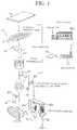
- the present embodiment performs this crushing through a coarsely crushing step performed by a two shaft crusher (crusher 110: ref. Fig. 1), which is a coarsely crushing means, and a fine crushing step performed by a one shaft crusher (cutter mill 120), shown in Fig 2, which is a fine crushing means. Therefore, in the present embodiment, the crushing step includes the two steps of coarsely crushing step and fine crushing step.
- the crushing means is configured by combining the previously mentioned two shaft crusher and one shaft crusher.
- the gainax crusher made by Horai Co., Ltd.
- the roll crusher made by Nara Machinery Co., Ltd.
- various known monocutters, shredders, crushers and the likes in the following, these will be collectively called “crushers" may be used.
- This crusher 110 shown in Fig. 1 as one example, is equipped with two parallel shafts which mutually rotate at the same time towards the inside of the crusher body, with several rotating knives placed at a specific interval on each shaft, and it is equipped to cut coated granules into crushed pieces which consist of fragments of suitable size, with 3 nails protruding from the peripheral face of each rotating knife so as to form isometric angles, with each shaft being engaged with the other at the periphery of each rotating knife.
- the coated granules are charged from the charging port of the upper portion of the crusher, pulled inside by the nails of the rotating knives from the two shafts which rotate mutually inwards, while being slit by the shearing force applied continuously between the edges at the periphery of the rotating knives which rotate in an engaged state, and are then crushed and cut by the pressure applied when pulling in, to form crushed pieces.
- the sizes of the previously mentioned nails and edges are selected in such a way that the sheathing board, which is the processing object, is crushed coarsely into approximately 20 x 50 mm portions, the crushed pieces formed by crushing the processing object into the previously mentioned size, pass through the screen installed under the previously mentioned rotating knives from the two shafts, and are discharged from discharge port.
- chips 81 formed in this way are crushed coarsely into the chips 81 of undefined shape such as polygon forms such as rectangles and squares, triangles, trapezoids and rhomboids, and are discharged from the previously mentioned discharge port.
- the chips 81 crushed coarsely as above are crushed into chips having, as one example, a size wherein a side is between 3 and 35 mm, through a known crushing means which is, for example in the present embodiment, the one shaft crusher (for convenience, called “cutter mill” in the present description), and this constitutes the coated particles 82.
- a known crushing means which is, for example in the present embodiment, the one shaft crusher (for convenience, called “cutter mill” in the present description), and this constitutes the coated particles 82.
- a cutter mill which is one example of crushing means, is shown in Fig. 2.
- Numeral 121 is a cutter mill main body, which is a casing forming a cylindrical shape having a charging port 123 on the upper side.
- a cutter supporter 124 is installed, which rotates in the vertical direction via a rotation driving means not shown, and whose axis is borne in the cutter mill main body 121.
- 4 (four) long rotating knives 125 are installed in the horizontal direction so as to form isometric angles of 90 degrees around the direction of rotation of the cutter supporter 124. The tips of the blades of these 4 rotating knives 125 are positioned on the same rotation locus.
- 2 (two) fixed knives 126 are fixed to the cutter mill main body 121, at a position approximately symmetric to the locus of the tips of the blades of the rotating knives 125, the interior of the cutter mill main body 121 is divided by the 2 fixed knives 126, the cutter supporter 124 and the rotating knives 125, to form a charging chamber 127 and a crushing chamber 128.
- the previously mentioned charging port 123 communicates with the previously mentioned charging chamber 127.
- the clearance between the 2 fixed knives 126 and the rotating knives 125 can be freely adjusted to cut the coated granules to a desired size, or generally to crush.
- the crushing chamber 128 is delimited by a mesh screen 129 in such a way such as to surround the periphery of the rotation locus of the rotating knives 125 of the 2 fixed knives 126 previously mentioned.
- the screen 129 uses punched metal in which numerous holes with diameters of between 5 and 20 are formed.
- a discharge port 139 is installed below the crushing chamber 128, for discharging crushed pieces and encrusted materials, such as concrete, which were peeled from the surface of the chips 81 during crushing, that passed through the screen 129.
- the chips 81 which were formed by crushing coarsely with the previously mentioned crusher 110, are charged from the charging port 123, and then, by rotating the cutter supporter 124 at, as one example, 800 min -1 by a rotation driving means (power of 5.5KW) not shown, the chips 81, which were formed by crushing coarsely, are crushed coarsely between the rotating knives 125 of the cutter supporter 124 and the fixed knives 126, into chips of undefined shape such as, polygons such as rectangles and squares, or triangles, trapezoids, or rhomboids, with unspecified form and surface.
- undefined shape such as, polygons such as rectangles and squares, or triangles, trapezoids, or rhomboids
- the charged chips 81 By using punched metal having a diameter of between 5 and 20 mm as the screen 129, at the same time, by suitably adjusting the operation time, the charged chips 81 become the coated particles 82 with a size having a length or a diameter of between 3 and 35 mm. These coated particles 82 do not pass through the screen 129, and remain inside the crushing chamber 128.
- the reason for setting the size of the coated particles 82, which are to be brought to the next step, as previously described to between 3 and 35 mm lies in the fact that, on one hand, if one side of the coated particles 82 is less than 3 mm, they are finely crushed during the step of separation, classification and size regulation described below, which decreases the amount of synthetic wood materials which is recycled as regeneratable materials, while on the other hand, if it is set to greater than 35 mm, the processing capacity of the step of separation, classification and size regulation is decreased.
- the cutter mill 120 is represented as being equipped with a rotation shaft oriented in the horizontal direction.
- the cutter mill 120 used in the present invention may be a cutter mill having a rotation shaft oriented in the vertical direction, and any other types of cutter mill may be used.
- any apparatus, other than the cutter mill 120 may be used, as long as it is capable of processing the chips 81 into coated particles with defined size.
- Scraping impact force is applied to the coated particles 82, formed in the crushing step as indicated above by crushing the sheathing board 1a, which was used as a concrete form 50, into undefined forms having one side of between approximately 3 and 35 mm, concrete still encrusted to the surface of the coated particles 82, and other encrusted materials are peeled or eliminated, and at the same time, synthetic wood materials are recovered, such as the synthetic wood materials deteriorated by repeated usage such as the region corresponding to the surface of the sheathing board 1a, by applying the previously mentioned scraping impact force, to slightly trim the coated particles 82 themselves so as to regulate and transform them into raw materials.
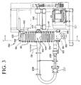
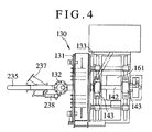
- FIGs 3 through 5 An example of configuration of the means for separating, classifying and size regulating of particles used in the present invention (for convenience, called “cleaning separator” in the present embodiment) is shown in Figs 3 through 5.
- the cleaning separator 130 is equipped with a supply charging port 132 for charging with each of the coated particles 82, a collection port 153 for collection of synthetic wood materials from which encrusted materials, such as concrete still encrusted to the coated particles 82, have been peeled and eliminated by treating the coated particles 82 inside the cleaning separator 130, and a discharge port 152 to discharge encrusted materials peeled from the previously mentioned coated particles 82, and dust and the like generated by trimming the coated particles 82 themselves by applying scraping impact force.
- a supply charging port 132 for charging with each of the coated particles 82
- a collection port 153 for collection of synthetic wood materials from which encrusted materials, such as concrete still encrusted to the coated particles 82, have been peeled and eliminated by treating the coated particles 82 inside the cleaning separator 130
- a discharge port 152 to discharge encrusted materials peeled from the previously mentioned coated particles 82, and dust and the like generated by trimming the coated particles 82 themselves by applying scraping impact force.
- the coated particles 82 processed through the previously mentioned crushing step are supplied to the previously mentioned supply charging port 132.
- the previously mentioned collection port 153 communicates with the supply charging port 132 via a communicating pipe 235.
- Piping 236 communicates with the collection port side of the communicating pipe 235, from a compressed air supply source not shown.
- a flow regulating plate is installed at the communication site with this piping 236, and is configured to allow mainly compressed air to flow to the supply charging port 132.
- the communicating pipe 235 is branched, and a branch pipe 237 is installed for transferring to a recovery tank 240 to recover granulated synthetic wood materials 83.
- a three way electromagnetic valve 238 is installed, which can be switched at adequately set times using a timer circuit.
- the previously mentioned discharge port 152 is communicating with a collecting tank 250 through a discharge pipe 239, and is configured in such a way that dust 84 consisting of, for example, encrusted materials crushed and transformed into fine powders, and powders of synthetic wood materials generated by trimming the coated particles 82 themselves, is discharged from the discharge port 152, is aspirated into the discharge pipe 239, to which a blower 157 is separately installed, and recovered in the collecting tank 250.
- the cleaning separator 130 used in the present embodiment is a small type experimental apparatus, and has a processing capacity of 160 kg/h for the previously described coated particles 82.
- the previously described supply charging port 132 of this cleaning separator 130 is connected to, and opens into, the central portion of a fixed disk 131 having a diameter of 400 mm, a fixed terminal plate 133 closes the processing space 155 and faces the previously mentioned fixed disk 131, and the respective peripheral outer edges of the previously mentioned fixed disk 131 and of the fixed terminal plate 133 are fixed with a peripheral plate 135.
- the fixed terminal plate 133, and a mobile disk 141 having approximately the same diameter as the fixed terminal plate 133 are installed, the mobile disk being driven into rotation by a horizontal rotation shaft 142, and the horizontal rotation shaft 142 being supported by each bearing 143 and 143.
- the previously mentioned horizontal rotation shaft 142 is driven into rotation by a rotation driving means such as a motor 161, which, in the present embodiment, as one example, is rotated at 750 min -1 .
- each fixed pin 134 is sequentially planted onto the previously mentioned fixed disk 131 at several rotation loci a1 - a6 (Fig. 5) which are concentric (relatively to the corresponding mobile disk 141).
- each mobile pin 144 distinct from each of the previously mentioned fixed pins 134, is sequentially planted onto the previously mentioned mobile disk 141 at several rotation loci b1 - b6, inserted alternately between the rotation loci of each of the previously mentioned fixed pins 134.
- This arrangement makes it possible to obtain a step wherein encrusted materials such as concrete encrusted on the surface of coated particles 82 are peeled or separated, and a step wherein coated particles 82 are granulated into spheres, by the scraping impact force between each of these fixed and mobile pins 134 and 144.
- the number of fixed pins 134 is 16 at the rotation locus a1, which is close to the central portion of the fixed disk 131, and 24 are planted at the rotation locus a2, which is situated at the periphery of the previously mentioned rotation locus a1.
- the number of fixed pins 144 is 4 at the rotation locus b1, which is close to the central portion of the mobile disk 141, and 4 are planted at the rotation locus b2, which is situated at the periphery of the previously mentioned rotation locus b1.
- a specific mesh screen 151 in which pores have been punched, is installed peripherally, closing a discharging space 156, and a discharge port 152 is installed below the discharging space 156.
- the previously mentioned screen 151 is a mesh having, as one example, pores with a diameter of 1.2 mm.
- a collection port 153 is installed at the lower part inside the screen 151 of the processing space 155.
- This collection port 153 is communicating with the supply charging port 132 through a communicating pipe 235, and is communicating with the recovery tank 240 for recycling the recycled granulated synthetic wood materials 83, through a branch pipe 237 which branches the supply charging port side of the communicating pipe 235.
- a plug valve for controlling opening and closing may be installed on the previously mentioned collection port 153, and the collection port 153 may be connected to the supply charging port 132 through a blower 158 which aspirates the air inside the cleaning separator 130, as shown in Fig. 1.
- each coated particle 82 when each coated particle 82 is supplied to the supply charging port 132 by rotating the mobile disk 141 with the horizontal rotation shaft 142 which is rotated by the rotation driving means of the motor 161, each coated particle 82 is at the central portion of the processing space 155, and each coated particle 82 is struck by the scraping impact force between each of the fixed and mobile pins 134 and 144 and by the impacts from each of the fixed and mobile pins 134 and 144, and in addition, by rubbing each of the pins 134 and 144 against the surfaces of the coated particles 82, or by rubbing the surfaces of the coated particles 82 against each other, the surfaces of the coated particles 82 are scraped in such way that encrusted materials, as well as deteriorated synthetic wood materials which are encrusted on the surfaces, are finely crushed into dust form, and are peeled from the surfaces of the particles 82.
- encrusted materials peeled from the previously mentioned coated particles 82, and synthetic wood materials in dust form generated by trimming the coated particles 82 themselves are aspirated together with the air inside the cleaning separator 130, at 15 kw, 460 mm Aq pressure and 65 m 3 /minute aspiration speed for large machines, at 3.7 kw, 460 mm Aq pressure and 51 m 3 /minute aspiration speed for medium machines, and at 1.5 kw, 400 mm Aq pressure and 3.4m 3 /minute aspiration speed for small machines, as the previously mentioned blower 157.
- coated particles 82 of sizes which do not pass through the screen 151 accumulate inside the screen 151. Coated particles 82 with encrusted materials still encrusted on their surfaces are mixed among the coated particles 82 from which these encrusted materials have been eliminated. However, since the collection port 153 and the supply charging port 132 communicate with each other through the communicating pipe 235, the coated particles 82 extracted from the collection port 153 flow back to the supply charging port 132, repeatedly scraped in the cleaning separator 130 by receiving scraping impact forces again, encrusted materials such as concrete, encrusted on the surfaces of the coated particles 82 are peeled from the coated particles 82, and only the synthetic wood materials constituting the coated particles 82 remain.
- coated particles 82 from which encrusted materials have been eliminated as described above, flow back, the majority remain inside the screen 151 without being scraped up to a point so as to pass through the screen 151.
- the above step of separation, classification and size regulation can be reiterated several times as needed until the encrusted materials of the coated particles 82 within one batch are separated.
- each coated particle 82 within one batch is supplied through the supply pipe 231 to the supply charging port 132, at the same time as the coated particles 82 are granulated into approximately spherical forms by the scraping impact forces applied to the coated particles 82, powders formed by finely crushing encrusted materials which are peeled from the surface of the coated particles 82 by the processing inside the cleaning separator 130, and the dust 84 formed from synthetic wood materials or the like generated by trimming one portion of the coated particles 82 themselves, said powders and dust pass through the screen 151 and are discharged to the collecting tank 250 by the blower 157, on the other hand, the coated particles 82 remaining inside the screen 151 are aspirated into the communicating pipe 235 by the circulating air flow and are again fed into the processing space 155, processed inside the cleaning separator 130, and this suite of step is repeated over several times as needed until the encrusted materials on the surfaces of the coated particles 82 of one batch are peeled.
- an electromagnetic valve which opens and closes the previously mentioned branch pipe 237 and an electromagnetic valve which opens and closes the down stream side of the previously mentioned communicating pipe 235 may be installed, and set up so that these two electromagnetic valves to open and close alternately.
- encrusted materials such as concrete encrusted on the coated particles are peeled from the surface of the coated particles, and at the same time are classified from the synthetic wood materials crushed and granulated into approximately spherical forms by the scraping impact forces applied in the previously mentioned step.
- dust 84 of encrusted materials and the like generated by crushing with these scraping impact forces is not completely recycled in the preceding step, and dust 84 exists still mixed among the granulated synthetic wood meal materials 83
- these recycled granulated synthetic wood meal materials 83 are sifted through a sieve 100 of the present step, and the dust 84 mixed among the granulated synthetic wood meal materials 83 is eliminated.
- the sieve 100 used in the present step may have any configuration, provided it can eliminate fine powder of encrusted materials mixed among the granulated synthetic wood meal materials, as previously described, and various conventional sieves may be used.
- a vibratory sieve (Sato model vibratory sieve made by Mie Industry Co., Ltd.) is used as this sieve 100.
- a sieve equipped with a screen having a grid spacing of between 1 to 5 mm, preferably of between 2 to 4 mm, and actually of 3 mm in the present embodiment, is used.
- the granulated particle resin materials 83 recycled through the previously mentioned step of separation, classification and size regulation are sifted through the sieve 100 of the present step, such that dust of encrusted materials and synthetic wood materials, which passed through the screen, are eliminated, and the granulated synthetic wood meal materials, which did not pass through the screen and remained above the sieve, are recycled as regeneration materials for sheathing boards.
- the present step is a step wherein the granulated synthetic wood meal materials 83, recycled as regeneration materials through the previously mentioned fine classification step, are dried to a moisture content of less than 0.1 wt %.
- the sheathing board 1a of the present invention contains an important amount of cellulose crushed materials such as wood meal, and there are cases where moisture is absorbed when used as the concrete form 50, or during storage, and when the granulated synthetic wood meal materials 83 which have been granulated in a condition wherein moisture has been absorbed in this way are directly used as regeneration materials, regeneration of the sheathing board 1b can not be performed optimally.
- This drying step is performed using a conventional dryer 102, and in the present embodiment, a dryer made by Matsui MFG Co., Ltd. is used as this dryer 102. If the granulated synthetic wood meal materials recycled in the previously described way, are dried in this dryer for approximately 1 hour at a temperature of, in the present embodiment, 90 C, the granulated synthetic wood meal materials 83 with a moisture content of approximately 1.8 wt % before processing is dried to a moisture content of less than 0.1 wt %, and become adequate as regeneration materials for the sheathing board 1b.
- the previously mentioned drying temperature was set to 90 C in the present embodiment, since the granulated synthetic wood meal materials 83 melt when drying the granulated synthetic wood meal materials 83 at a temperature of greater than 90 C, and, when performing drying at lower temperatures, processing by the present step requires a longer time.
- the moisture content of the granulated synthetic wood meal materials 83 after drying is greater than 0.1 wt %, the quality of the regenerated sheathing board decreases.
- the previously mentioned drying temperature, the processing time and the like can be suitably changed according to the type of resin constituting the granulated synthetic wood meal materials 83 which is the processing object, and other various conditions.
- the granulated synthetic wood meal material 83 recycled and dried in the above described way, is regenerated again into, as one example, the sheathing board 1b for use in a concrete form, either directly, or mixed with thermoplastic resin materials, which are either virgin or disposed of and recycled, and cellulose crushed materials, the synthetic wood materials having a moisture content of within 15 wt %, wherein between 20 and 75 wt % of cellulose crushed materials, such as wood meal with particle diameters of between 50 and 200 ⁇ m, and between 25 and 80 wt % of thermoplastic resin molding materials, are mixed.
- numeral 1 is a sheathing board for use in a concrete form of the present invention, fabricated with the previously mentioned recycled synthetic wood materials as raw materials.
- This sheathing board 1 is a sheathing board having the granulated synthetic wood meal materials 83 recycled in the previously described way as molding materials, and formed by molding this granulated synthetic wood meal materials 83 through extrusion molding to form hollow chambers within the thickness of the board.
- the granulated synthetic wood meal materials 83 recycled in the previously described way, while being heated and kneaded by an extruder, are extruded into a molding die, and are molded so as to have a thickness of between 12 and 50 mm, preferably of between 12 and 15 mm, more preferably of between 16 and 20 mm, a width of between 300 and 900 mm, preferably of between 600 and 900, more preferably of 600mm, and a length of between 1500 and 2000 mm, preferably of between 1500 and 1800 mm, and more preferably of 1800 mm.
- the previously mentioned sheathing board 1 several hollow chambers 2 are formed in the direction of its length, and the previously mentioned hollow space is formed in such a way such that the thickness of each wall delimiting these hollow chambers 2 is at least greater than 2 mm, preferably between 3 mm and 6 mm, and the hollowness is between 20 and 70 %.
- the hollowness is the proportion of the volume of the hollow chambers 2 with respect to the total volume of the sheathing board comprising the hollow chambers 2.
- numeral 70 is a single shaft extruder.
- an extruder is of screw type, available as a single shaft extruder or a multiple shaft extruder; and it is available having a structure which is a variation of these or a combination of these, and any of these extruders may be used for the present invention.
- Numeral 71 is a screw of single shaft type. This screw 71 is driven through a speed reduction gear 72 by a motor not shown, and rotates inside a barrel 74. The granulated synthetic wood meal materials 83 charged from a hopper 73 are kneaded by this screw 71 in rotation and are extruded to the front of the screw 71.
- a band heater 75 is installed on the outer surface of the barrel 74, and the granulated synthetic wood meal materials 83 inside the barrel 74 are heated by this band heater 75, while being gradually melted and kneaded along the groove of the screw 71 and conveyed to the front. Then, through a screen 76 and an adapter 17, the kneaded materials are extruded, as an extruding materials 79, from an extruding die 19 of the adapter 17 to a molding die 10.
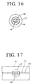
- the extruding die 19 at the front end of the barrel 74 forms an elongated rectangular shape equipped with an ejection port 50 mm wide and 18 mm high, which has a front end formed with a thickness of 8 mm (see Fig. 17).
- a communicating hole is formed, wherein the cross section changes gradually from an inflow port 18 of the rear end face of the adapter 17 having a diameter of 50 mm, to the ejection port of the previously mentioned extruding die 19.
- the inflow port 18 is formed with the same size as the circular cross section of the ejection port of the extruder 70, while on the other hand it is preferable that the width of the rectangular shape of the extrusion die 19 is formed with the same size as the diameter of the inflow port 18, and its height is formed with the same size as the height of a molding chamber 22 of the molding die 10 described later.
- the adapter 17 and the extruding die 19 may be formed in various sizes according to the size of the extruder 70.
- the diameter of the inflow is 150 mm
- the width of the rectangle of the extruding die 19 may be of 150 mm and the height may be the same as the height of the molding chamber 22, which is of 18 mm.
- the inflow port 18 of the adapter 17 and the screen portion of the extruder 70 communicate by connecting the rear end of the previously mentioned adapter 17, through a fixture interlocked at the outer periphery of said adapter, to the front end face of the screen portion equipped with a screen 76 (Fig. 8) of the extruder 70, with fasteners such as bolts.
- the extruding die 19 and the lead-in portion 11 of a molding die 10 communicate by mounting the front end of the ejection port having a rectangular cross section, of the front end of the extruding die 19, onto the lead-in portion 11 having a rectangular cross section formed at an approximately central position of the rear end of the molding die 10.
- a heater serving as a heating means may be buried inside the surrounding wall of the communicating hole of the previously mentioned adapter 17.
- Such a flowing state of the extruded materials 79 is excellent.
- the previously mentioned extruding die 19 differs from a typical general die, having a large ejection port allowing for a large amount of melted raw materials (synthetic wood meal) to be delivered, and moreover, it is formed into a shape wherein promoting compaction becomes possible, which means that clogging of the die as was occurring with a typical die does not occur.
- numeral 10 is a molding die, and consists of a lead-in portion 11 which pushes out the extruded materials 79 delivered from the ejection port of the extruding die 19 having a rectangular cross section, of the extruder 70, and a molding chamber which molds the extruded materials 79 pushed out from the lead in portion 11 into a board form having a wide width and a specific thickness, in the present embodiment, a molding chamber 22 forming an elongated rectangular cross section with a width of 600 mm and a height of 18 mm.
- Numeral 11 is the lead-in portion, formed inside the molding die 10, in the direction of the width of the molding die 10, formed with a width approximately equal to or slightly larger than the previously mentioned extruder die 19.
- the shape of the horizontal cross section is formed into a so called coat hanger type wherein both edges of the lead in chamber 13, which extend by curving towards the direction of the width of the molding die 10, reach both edges of the long direction of the molding chamber 22.
- the previously mentioned lead-in chamber 13 may be formed into a straight manifold type, in addition to the coat hanger type, the previously described curved shape coat hanger type is preferred, owing to the excellent fluidity of the extruded materials 79 flowing inside the lead in portion 11 and the lead in chamber 13.
- a sheet 24 formed with fluororesin described later is preferably affixed on the previously mentioned lead in portion 11 and the lead in chamber 13.
- the previously mentioned molding chamber 22 is formed into a square cross section by metal spacers, not shown, wherein two metal plates, one upper and one lower, having a heating and a cooling means, are placed at the border of both sides, and adjustments may be made by exchanging the previously mentioned spacers, to obtain any target thickness for the hollow resin molded board.
- the molding die 10 has, as one example, an elongated rectangular cross section with a width of 600 mm and a height of 18 mm, and a distance from the inlet of the molding chamber 22 to the die outlet 23 (the distance in the direction of pushing out) of 1,000 mm.
- the sheet 24 made of fluororesin and 0.25 mm thick is affixed.
- the previously mentioned sheet 24 is a sheet made of glass woven fabric with a film of fluororesin coated on its surface.
- teflon TFT, teflon FEP, teflon CTFE, teflon Vdf or the like are available as fluororesin.
- the previously mentioned glass woven fabric may be a non woven fabric of glass fibers.
- the previously described step of coating with fluororesin may be performed on the upper and lower inner surfaces of the molding chamber 22, in other words, on the inner wall surfaces corresponding to the surfaces which form the front and the back surfaces of the hollow resin molded board forming the sheathing board.
- numerals 14 are heaters, which consist of a heating means such as electrically heated heaters, and are installed as piping, by inserting four such heaters at equal intervals into the molding die 10 above and below the molding chamber 22, corresponding to the melting section 21a containing the lead in portion 11 spanning one fourth of the longitudinal direction of the whole molding die 10, for heating and maintaining the temperature of the extruded materials 79, and for sustaining the fluidity of the extruded materials 79.
- a heating means such as electrically heated heaters
- numerals 25 are cooling pipes, representing one example of cooling means to cool the annealing section 21b of the molding chamber 22 of the molding die 10, to cool the extruded materials 79 inside the molding chamber 22, by supplying the cooling pipe 25, at appropriate intervals in the pushing out direction of the molding chamber 22, with a cooling liquid serving as a cooling medium, such as water at room temperature, or water up to approximately between 70 and 80 C, or oil.
- the pipes of these cooling pipes are installed as piping, by inserting 8 such pipes at equal intervals in the molding die 10 above and below the molding chamber 22, in the annealing section 21b accounting for three fourths in the direction of the die outlet 23 of the molding die 10, to improve the annealing effect inside the molding chamber 22 on the extruded materials 79.
- cooling pipes 25 may be installed by gradually narrowing the intervals, or, the cooling pipes 25 may be placed on the outer wall of the molding die 10, the construction is not restricted to this construction since it suffices to cool the extruded materials 79 inside the molding chamber 22.
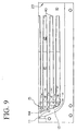
- the core 40 used when fabricating the sheathing board for use in a concrete form wherein hollow chambers are formed with a defined interval in the thickness.
- the core 40 is integrated with a base portion 44, having an arc shaped cross section, and a guiding portion 15 provided with an inclined part 43 which is inclined in the direction of the die outlet 23.
- the core 40 consists of a molding guide portion 41, located in the melting portion 21, formed by an approximately half portion situated on the side of the guiding portion 15, forming an overall shape of approximate comb teeth, with seven rod shaped members having a rectangular cross section, and a total length of 800 mm and a width of 35 mm, and an extraction guide portion 42 located in the annealing portion 21b, wherein a taper of one thousandth is formed in both the thickness and width, from this molding guide portion 41 and in the direction of the die outlet.
- the previously mentioned guiding portion has, in the lead-in chamber of the previously mentioned molding die, a total length of between 70 and 95 % of the total length in the direction of the width of said lead in chamber. Moreover, it is preferably set at less than 70 % of the height of said lead in portion, and one fourth of it, from the guiding portion 15 of core 40 in the direction of the front end die outlet 23, is located in the melting portion 21a of the molding chamber 22, and the remainder is located in the annealing portion 21b.
- the molding guide portion 41 of the previously mentioned core 40 is formed linearly with a thickness of less than 45 % of the height of the previously mentioned molding die, with the same thickness at the center of the molding die.
- the thickness of the extraction guide portion 42 is tapered in the direction of the front end of the die outlet 23.
- the previously mentioned core 40 is respectively aligned into several columns parallel to the longitudinal direction of the molding chamber 22, in other words parallel to the direction of the pushing out, with an interval of four sevenths of the width of the core 40.
- the previously mentioned guiding portion 15 and core 40 have all the outer surfaces affixed with sheets made of fluororesin such as teflon, with a thickness of between 0.1 and 0.5 mm.
- This guiding portion 15 is placed inside the previously mentioned lead in chamber 13 with a height of 18 mm and a width of 600 mm, approximately in the center, creating an interval of 28.5 mm each, in the direction of the width of the lead in chamber 13 and both ends in the direction of the width of the molding chamber.
- the back end side of the guiding portion 15 is placed so as to obtain an interval approximately parallel to the surface of the front end wall of the lead in portion 11, this guiding portion 15 being fastened to the molding die 10 on the surface below the lead-in chamber 13 with bolts 27 as shown in Fig. 12. Therefore, a gap is also formed between the upper surface of the guiding portion 15 and the upper surface of the lead-in chamber 13.
- the thickness of the plates, and the width and the interval of the guiding portion 15 and the core 40 may be suitably selected according to the capacity of the molding chamber 22.
- 42 cores 40 having a square form cross section of 10 x 10 mm are placed with a spacing of 3 mm.
- bearings 34a for supporting the two ends of the shafts of three free pinch rollers 31b are respectively fixed to a bearing fixation frame 36, fixed pinch rollers 31a are driven by the gears 116 installed on each shaft, and gears 177 engaging with these gears 116.
- the powder break is a so called electromagnetic break, and allows fine electrical adjustment of friction torque.
- frames 114 are installed on the bearing fixation frame 36.
- Two block shaped guide members 119 with guiding grooves are respectively installed on the surface of the wall of this frame 114, with the direction of the axial line of the guide member 119 oriented approximately parallel to the up and down directions.
- Bearings 34b for supporting the two ends of the shafts of each of the three free pinch rollers 31b are installed to move freely upwardly and downwardly along the guiding grooves of the previously mentioned guide member 119, and the previously mentioned bearings 34b are respectively connected to the front ends of rods of three air cylinders 118 installed on the upper surface of the frames 114.
- the three free pinch rollers 31b are respectively pressed against the fixed pinch rollers through a hollow resin molded board 29.
- the rotation of the shaft of one fixed pinch roller 31a among the three fixed pinch rollers 31a is restricted by the powder break 115, and since the gear 116 installed on the shaft of this fixed pinch roller 31a is engaged with the gears 116 and 116 installed on the shafts of the other two fixed pinch rollers 31a and 31b, through the shafts 117 and 117, the same rotation restriction force is applied on the three fixed pinch rollers 31a by the friction torque of the powder break 115.
- the friction torque for restricting the rotation of the fixed pinch roller 31a by the powder break 115 is adjusted by the thickness of the hollow resin molded board 29 to be formed.
- the friction torque of the powder break 115 is a restriction force against the force pushing out the hollow resin molded board 29, such that the extruded materials 79 inside the lead in portion 11 of the molding die 10 are in a more uniform and more dense state.
- These uniform and dense extruded materials 79 are pushed out by the force of the extruded materials 79 generated by the extruder 70, proceed while resisting against the restriction force of the previously mentioned coarsely crushing means 30, and are then cooled inside the molding chamber 22 and form the hollow resin molded board 29.
- This hollow resin molded board 29 proceeds by resisting against the restriction force of the powder break 115, rotating the previously mentioned fixed pinch rollers 31a and the free pinch rollers 31b.
- the previously mentioned restriction force provides the extruded materials 79 both inside the molding chamber 22 and inside the lead-in portion 11, through the hollow resin molded board 29, with a resistance against the force applied by the extruder, which pushes out the extruded materials 79 inside the molding chamber 22, and the entire extruded materials 79 inside the molding chamber 22 become more uniform and of higher density.
- a restriction force to the hollow resin molded board 29, the density of the extruded materials 79 increases, and therefore, the formation of air bubbles, foci and the likes is prevented. Consequently, a more uniform more dense and more lightweight hollow resin molded board is formed.
- the sheathing board for use in a concrete form molded in the above described way may be used as a sheathing board, after eliminating the skin layer of the surface by, for example, a sanding treatment of its surface, or without performing such processing, i.e. in the same state as when it was molded.
- a sheathing board made of resin to replace a sheathing board made of plywood could be obtained, wherein the sheathing board of the present invention was obtained as described above, having characteristics that are extremely close to those of natural wood.
- its relative density is approximately as lightweight as a sheathing board made of plywood, and processing, such as cutting and drilling with manual tools, is relatively easy.
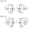
- spacers 3 and 3 are mounted on the surface of one side, for example, at the opposite two edges of the sheathing board 1 of the present invention.
- the mounting of spacers 3 and 3 allows the formation of specific concrete assemblies. For example, by opposing the two sheathing boards 1 and 1 through the faces which are opposite to the side where the spacers 3 and 3 are mounted, concrete is cast between these boards 1 and 1, and a concrete wall having the thickness corresponding to this interval between the sheathing boards 1 and 1 is formed.
- a separator 61 serving as a connecting rod which connects between the sheathing boards 1 and 1, and stoppers 63 and 63 such as standard washers, wood-concrete or plastic cones mounted on the two ends of the previously mentioned separator 61, for controlling the interval between the sheathing boards 1 and 1, and maintaining the interval of the spacing between the sheathing boards 61, prevent the interval of the space between the sheathing boards 1 and 1 from narrowing, and at the same time, by means of the form tighteners 62 and 62, connected to one end of the previously mentioned stoppers 63 and 63, and piercing and protruding from the sheathing boards 1 and 1, nuts 64 and 64, which screw into the threads formed at the other end of the previously mentioned tighteners 62 and 62, and the washers 65 and 65 and the like, which are pressed in the direction of the sheathing boards 1 and 1 by the tightening of the previously mentioned nuts 64 and 64, it is possible to press in the direction of the sheathing boards
- the previously mentioned separator 61 is installed in the space maintained between the sheathing boards 1 and 1, and is used as a connecting rod connecting the sheathing board 1 and 1. Also, at the periphery of both ends, a male thread is formed, at both ends of the separators 51 and 51 stoppers 63 and 63 such as washers, wood-concrete or plastic cones are mounted and the stoppers 63 and 63 strike the surface of the inner wall of the sheathing boards 1 and 1 to prevent the interval between the sheathing boards 1 and 1 narrowing. As one example, in the present embodiment, standard plastic cones are used as these stoppers 63 and 63.
- the plastic cones used as the stoppers 63 and 63 consist of a flat topped cone shaped body wherein a nut or the like is buried and a screw hole is formed which pierces the center, the end portion of the previously mentioned separator is screwed and inserted from the end at the small diameter side up to the approximate center of this plastic cone, and the previously mentioned plastic cones are fixed at both ends of the separator.
- the form tighteners 62 and 62 are mounted on the other end of the plastic cones which are screwed on both ends of the separator in the above described way.
- These form tighteners 62 and 62 are formed from iron poles having the same diameter as that of the previously mentioned separators 61 and 61, and similarly to the previously mentioned separators, male screw threads are formed at the peripheries of their two ends, and they are stabilized by screwing and inserting one end into the screw hole which pierces the center of the plastic cones from the end on the larger diameter side.
- the construction may be such that, as an alternative to the washers through which the previously mentioned form tighteners run, as shown in Fig 20, curved washers 65' and 65' are mounted, and iron pipes are used as the horizontal flaps 52 and 52, fixed by the curved surface of these curved washers 65' and 65'.
- the spacers 3 and 3 are mounted along the two edges constituting the short edges of the sheathing board 1 formed to have a width of 600 mm, and a length of 1,800 mm, and at the same time as aligning several layers of this sheathing board 1, the horizontal flap 52 is positioned with an interval of approximately 750 mm, the vertical flap 51 is positioned with an interval of approximately 300 mm, and the previously mentioned separator 61 is installed with an interval in the vertical direction of approximately 750 mm, and with an interval in the horizontal direction of approximately 600 mm.
- the sheathing board 1 of the present invention may be positioned by taking the direction of the length as the direction of the height, as shown in Fig. 23 (A) and Fig. 23 (B), by mounting the spacers 3 and 3 along the two edges constituting the direction of the length of the sheathing board, as shown in Fig. 22.
- a sheathing board of the present invention was fabricated under the conditions indicated below (in the table, immaculate means example of immaculate sheathing board).
- extruder diameter 115 mm single shaft extruder clearance 0.2 mm (space between the screw 71 and the barrel 74) molding die 10 width: 730 mm Height: 420 mm (vertical section in the direction of the width) length of the molding die 1.000 mm (from the inlet of the molding chamber to the die outlet) delivery amount hollow immaculate 115 kg/h 198 kg/h particle diameter of raw materials mean particle diameter less than 120 mesh combination thermoplastic resin PP 45 wt % actual relative amount 0.9 wood meal 55 wt % water content 0.1 wt % actual relative amount 1.2 ⁇ 1.4 production capacity hollow immaculate approx. 15 m/h approx. 25 m/h
- a sheathing board for use in a concrete form was formed, by cutting a hollow board formed by extrusion, having a width of 600 mm, a thickness of 18 mm and a hollowness of 38.9% to a length of 1,800 mm.
- This sheathing board has 42 hollow spaces formed, having a rectangular cross section of 10 mm x 10 mm formed in the direction of the length of the sheathing board, in a width of 600 mm with an interval of 3 mm, and its weight is approximately 13.3 kg.
- the width is 12 mm, and the weight is approximately 14.3 kg.
- the bending strength of the sheathing board of the present invention was evaluated under the conditions described below.
- sheathing board used as testing materials are identical to those fabricated in the previously mentioned example of fabrication.
- the sheathing board of the present invention has a bending strength of approximately twice the standard value in the "concrete standards specifications (application)" established in Hei 8.(1998), and has an adequate strength to be employed as a sheathing board for use in concrete form.
- the sheathing board of the present invention (without a mold release agent coat), and a sheathing board made of plywood coated with a mold release agent, which were respectively not reused or reused three times were used to perform casting of concrete, the state of the surface of the sheathing board after mold release was visualized and inspected.
- the results are shown in Table 3.
- the sheathing board of the present invention has an excellent mold releasing property even after repeated use, and it is shown that the board can endure repeated use, and has a long lifespan.
- sheathing board of the present application sheathing board made of synthetic wood item non reused reused three times non reused reused three times state of the surface ⁇ ⁇ ⁇ ⁇
- the testing conditions were identical to the previously described the bending test with non regenerated sheathing board(Table 2).
- the bending strength (sustain rate) of the sheathing board regenerated by the method of the present invention decreases by only approximately 2 % and this decrease is almost unnoticeable, showing clearly that it has an adequate bending strength to be employed as a regenerated sheathing board for use in concrete form.
- Table 4 comparative tests on the bending strength between the regenerated sheathing board and the non regenerated sheathing board.
- a concrete mold was assembled, and concrete was cast inside this form, to fabricate a concrete wall having a height of 7405 mm, a width of 9500 mm and a width of 1500 mm.
- the conditions for assembling the form are as shown in Table 5.
- the concrete form assembled with the above conditions did not display bowing, deformation, breakage or the like, due to the casting of concrete, and clearly shows that the sheathing board of the present invention has adequate strength to be employed as a sheathing board for use in concrete form.
- the sheathing board for use in concrete form fabricated with recycled synthetic wood materials as raw materials is as lightweight as a sheathing board made of plywood, its workability is adequate and the handling is convenient, and at the same time, it has an adequate strength for use in concrete form, in addition, a form could be provided made of resin which can be regenerated after use by retransforming into materials. Therefore, in this way, the usage of sheathing boards made of plywood having natural wood as raw materials is reduced and an effective usage of the resources and the improvement of the natural environment can be achieved.
Landscapes
- Engineering & Computer Science (AREA)
- Life Sciences & Earth Sciences (AREA)
- Environmental & Geological Engineering (AREA)
- Mechanical Engineering (AREA)
- Manufacturing & Machinery (AREA)
- Wood Science & Technology (AREA)
- Forests & Forestry (AREA)
- Dry Formation Of Fiberboard And The Like (AREA)
- Processing Of Solid Wastes (AREA)
- Forms Removed On Construction Sites Or Auxiliary Members Thereof (AREA)
Applications Claiming Priority (2)
| Application Number | Priority Date | Filing Date | Title |
|---|---|---|---|
| JP2000391020A JP2001276643A (ja) | 2000-01-28 | 2000-12-22 | 木質合成材料から成るコンクリート型枠用のせき板から木質合成材料を回収する方法、及び前記回収した木質合成材料を原料としたコンクリート型枠用せき板。 |
| JP2000391020 | 2000-12-22 |
Publications (2)
| Publication Number | Publication Date |
|---|---|
| EP1216755A2 true EP1216755A2 (fr) | 2002-06-26 |
| EP1216755A3 EP1216755A3 (fr) | 2003-10-08 |
Family
ID=18857263
Family Applications (1)
| Application Number | Title | Priority Date | Filing Date |
|---|---|---|---|
| EP20010850131 Withdrawn EP1216755A3 (fr) | 2000-12-22 | 2001-07-27 | Procédé de recyclage de bois synthétique |
Country Status (2)
| Country | Link |
|---|---|
| US (2) | US6872442B2 (fr) |
| EP (1) | EP1216755A3 (fr) |
Cited By (4)
| Publication number | Priority date | Publication date | Assignee | Title |
|---|---|---|---|---|
| WO2006000593A1 (fr) * | 2004-06-28 | 2006-01-05 | Sita Deutschland Gmbh | Procede pour produire des materiaux a base de fibres |
| ES2584537A1 (es) * | 2015-03-27 | 2016-09-28 | Merivalor, S.L | Material compuesto sustitutivo de la madera resultado de la agregación de productos destinados a vertederos, procedimiento de obtención y planta industrial necesaria para tal fin |
| CN111037659A (zh) * | 2020-01-07 | 2020-04-21 | 李元飞 | 一种密度板加工用自动钻孔机 |
| WO2022095125A1 (fr) * | 2020-11-09 | 2022-05-12 | 绍兴市柯桥区锦策智能科技有限公司 | Dispositif d'extrusion pour matières premières en bois-matière plastique |
Families Citing this family (7)
| Publication number | Priority date | Publication date | Assignee | Title |
|---|---|---|---|---|
| US20080176053A1 (en) * | 2007-01-24 | 2008-07-24 | United States Cypsum Company | Gypsum Wallboard Containing Acoustical Tile |
| DE102007026155A1 (de) * | 2007-06-04 | 2009-01-08 | Fraunhofer-Gesellschaft zur Förderung der angewandten Forschung e.V. | Verfahren zur Erfassung von Prozessparametern und Holzwerkstoffprodukt |
| DE102013000593A1 (de) * | 2013-01-16 | 2014-07-17 | Cvp Clean Value Plastics Gmbh | Vorrichtung und Verfahren zum Entfernen von Verunreinigungen auf Kunststoffschnipseln |
| JP6252747B2 (ja) * | 2013-11-22 | 2017-12-27 | ポップリベット・ファスナー株式会社 | 接合装置及び接合方法 |
| HUE043747T2 (hu) * | 2015-09-11 | 2019-09-30 | Recyouest | Eljárás nem kívánt szennyezõdéseket tartalmazó termoplasztikus szálak újrafeldogozására |
| US9945120B1 (en) * | 2017-05-03 | 2018-04-17 | Yu-Tsai Wu | Plastic form and manufacturing method thereof |
| CN113478697B (zh) * | 2021-07-26 | 2023-03-24 | 安徽正瀚新材料科技有限公司 | 一种泡沫塑料制品的次品粉碎回收设备 |
Family Cites Families (7)
| Publication number | Priority date | Publication date | Assignee | Title |
|---|---|---|---|---|
| US3441959A (en) * | 1961-06-05 | 1969-04-29 | Us Plywood Champ Papers Inc | Textured panel and process of producing same |
| CH570869A5 (fr) * | 1973-03-23 | 1976-05-14 | Icma San Giorgio S R L Ind Cos | |
| US6004668A (en) * | 1992-08-31 | 1999-12-21 | Andersen Corporation | Advanced polymer wood composite |
| JPH07171831A (ja) * | 1993-12-17 | 1995-07-11 | Ube Ind Ltd | 樹脂型枠の再利用方法 |
| JPH09234710A (ja) * | 1996-02-29 | 1997-09-09 | Marui Sangyo Kk | 構築用合板の製造方法 |
| US6180257B1 (en) * | 1996-10-29 | 2001-01-30 | Crane Plastics Company Limited Partnership | Compression molding of synthetic wood material |
| JP2000027431A (ja) * | 1998-07-15 | 2000-01-25 | Masao Konishi | コンクリート型枠成形材 |
-
2001
- 2001-07-18 US US09/906,855 patent/US6872442B2/en not_active Expired - Fee Related
- 2001-07-27 EP EP20010850131 patent/EP1216755A3/fr not_active Withdrawn
-
2004
- 2004-03-11 US US10/797,121 patent/US20040175449A1/en not_active Abandoned
Cited By (5)
| Publication number | Priority date | Publication date | Assignee | Title |
|---|---|---|---|---|
| WO2006000593A1 (fr) * | 2004-06-28 | 2006-01-05 | Sita Deutschland Gmbh | Procede pour produire des materiaux a base de fibres |
| ES2584537A1 (es) * | 2015-03-27 | 2016-09-28 | Merivalor, S.L | Material compuesto sustitutivo de la madera resultado de la agregación de productos destinados a vertederos, procedimiento de obtención y planta industrial necesaria para tal fin |
| CN111037659A (zh) * | 2020-01-07 | 2020-04-21 | 李元飞 | 一种密度板加工用自动钻孔机 |
| CN111037659B (zh) * | 2020-01-07 | 2021-11-02 | 山东同其数字技术有限公司 | 一种密度板加工用自动钻孔机 |
| WO2022095125A1 (fr) * | 2020-11-09 | 2022-05-12 | 绍兴市柯桥区锦策智能科技有限公司 | Dispositif d'extrusion pour matières premières en bois-matière plastique |
Also Published As
| Publication number | Publication date |
|---|---|
| US6872442B2 (en) | 2005-03-29 |
| US20040175449A1 (en) | 2004-09-09 |
| EP1216755A3 (fr) | 2003-10-08 |
| US20020117565A1 (en) | 2002-08-29 |
Similar Documents
| Publication | Publication Date | Title |
|---|---|---|
| JP3566348B2 (ja) | 廃棄樹脂成形品の回収・造粒方法及び装置並びに前記回収樹脂材料を用いた木質合成板の製造方法。 | |
| KR100395226B1 (ko) | 열경화성수지발포체로이루어지는재생수지,열경화성수지발포체의재생방법및상기재생수지로이루어지는성형품의성형방법 | |
| DE4216638C1 (fr) | ||
| US6872442B2 (en) | Method for recycling synthetic wood materials from sheathing board for use in a concrete form formed by synthetic wood materials, and sheathing board for use in a concrete form having the previously mentioned recycled synthetic wood materials as raw materials | |
| KR101985373B1 (ko) | 폐합성 수지 재생 압출 성형 시스템 및 이를 이용한 수지 재생 방법 | |
| DE60018467T2 (de) | Behandlung von polymerschaum | |
| US6749138B2 (en) | Granulator | |
| AT512209B1 (de) | Vorrichtung zum aufbereiten von kunststoffmaterial | |
| WO2002032637A1 (fr) | Installation de traitement de caoutchouc usage | |
| KR102505591B1 (ko) | 각 2개의 믹싱존과 환기구를 가지는 폐합성수지 재생 압출장치 | |
| JP3543021B2 (ja) | 補強木質合成板の押出成形方法及び装置 | |
| CN102416675A (zh) | 基于机械物理法可产业化废旧热固性塑料再生工艺及设备 | |
| EP1422000B1 (fr) | Procédé et dispositif pour traiter des materiaux contenant un gaz propulseur | |
| US6325215B1 (en) | Method and apparatus for separating elastomeric particulates and fibers from a pulverized mixture | |
| IE20010057A1 (en) | Method for recycling synthetic wood materials from sheathing board for use in a concrete form formed by synthetic wood materials,and sheathing board for use in a concrete form having the previously mentioned recycled synthetic wood materials as raw materials | |
| CN120382578A (zh) | 一种鞋类制造用鞋底废料循环装置 | |
| JPH10166364A (ja) | 廃棄樹脂製バンパーの回収方法及び前記廃棄樹脂製バンパーから回収した回収樹脂材料から成る木質合成粉及びその製造方法、並びに、前記木質合成粉を用いた中空木質合成板。 | |
| JP2001276643A (ja) | 木質合成材料から成るコンクリート型枠用のせき板から木質合成材料を回収する方法、及び前記回収した木質合成材料を原料としたコンクリート型枠用せき板。 | |
| JP2872590B2 (ja) | 中空樹脂成形板の押出成形方法及び装置 | |
| JP3554606B2 (ja) | 軟質塩化ビニルから成る廃農フィルムを用いた版木及びその製造方法 | |
| CN202271460U (zh) | 基于机械物理法可产业化废旧热固性塑料再生设备 | |
| DE4420211C1 (de) | Verfahren und Vorrichtung zur Herstellung von Granulat aus Kunststoffen | |
| JPH10146829A (ja) | 廃棄樹脂成形品の回収・造粒方法及び装置、並びに前記回収樹脂材料を原料とした中空木質合成板の製造方法。 | |
| Mölder et al. | Grinding of waste paper and rice hulls with the Szego Mill for use as plastics fillers | |
| CN219505190U (zh) | 一种塑料加工用热熔装置 |
Legal Events
| Date | Code | Title | Description |
|---|---|---|---|
| PUAI | Public reference made under article 153(3) epc to a published international application that has entered the european phase |
Free format text: ORIGINAL CODE: 0009012 |
|
| AK | Designated contracting states |
Kind code of ref document: A2 Designated state(s): AT BE CH CY DE DK ES FI FR GB GR IE IT LI LU MC NL PT SE TR |
|
| AX | Request for extension of the european patent |
Free format text: AL;LT;LV;MK;RO;SI |
|
| PUAL | Search report despatched |
Free format text: ORIGINAL CODE: 0009013 |
|
| AK | Designated contracting states |
Kind code of ref document: A3 Designated state(s): AT BE CH CY DE DK ES FI FR GB GR IE IT LI LU MC NL PT SE TR |
|
| AX | Request for extension of the european patent |
Extension state: AL LT LV MK RO SI |
|
| 17P | Request for examination filed |
Effective date: 20040402 |
|
| AKX | Designation fees paid |
Designated state(s): AT BE CH CY DE DK ES FI FR GB GR IE IT LI LU MC NL PT SE TR |
|
| STAA | Information on the status of an ep patent application or granted ep patent |
Free format text: STATUS: THE APPLICATION IS DEEMED TO BE WITHDRAWN |
|
| 18D | Application deemed to be withdrawn |
Effective date: 20070201 |