EP1216760A2 - Générateur de puissance pour soudage par ultrasons avec controle digital de la fréquence et de la puissance - Google Patents
Générateur de puissance pour soudage par ultrasons avec controle digital de la fréquence et de la puissance Download PDFInfo
- Publication number
- EP1216760A2 EP1216760A2 EP01870279A EP01870279A EP1216760A2 EP 1216760 A2 EP1216760 A2 EP 1216760A2 EP 01870279 A EP01870279 A EP 01870279A EP 01870279 A EP01870279 A EP 01870279A EP 1216760 A2 EP1216760 A2 EP 1216760A2
- Authority
- EP
- European Patent Office
- Prior art keywords
- power
- frequency
- phase
- converter
- signal
- Prior art date
- Legal status (The legal status is an assumption and is not a legal conclusion. Google has not performed a legal analysis and makes no representation as to the accuracy of the status listed.)
- Withdrawn
Links
Images


Classifications
-
- B—PERFORMING OPERATIONS; TRANSPORTING
- B29—WORKING OF PLASTICS; WORKING OF SUBSTANCES IN A PLASTIC STATE IN GENERAL
- B29C—SHAPING OR JOINING OF PLASTICS; SHAPING OF MATERIAL IN A PLASTIC STATE, NOT OTHERWISE PROVIDED FOR; AFTER-TREATMENT OF THE SHAPED PRODUCTS, e.g. REPAIRING
- B29C65/00—Joining or sealing of preformed parts, e.g. welding of plastics materials; Apparatus therefor
- B29C65/02—Joining or sealing of preformed parts, e.g. welding of plastics materials; Apparatus therefor by heating, with or without pressure
- B29C65/08—Joining or sealing of preformed parts, e.g. welding of plastics materials; Apparatus therefor by heating, with or without pressure using ultrasonic vibrations
-
- B—PERFORMING OPERATIONS; TRANSPORTING
- B06—GENERATING OR TRANSMITTING MECHANICAL VIBRATIONS IN GENERAL
- B06B—METHODS OR APPARATUS FOR GENERATING OR TRANSMITTING MECHANICAL VIBRATIONS OF INFRASONIC, SONIC, OR ULTRASONIC FREQUENCY, e.g. FOR PERFORMING MECHANICAL WORK IN GENERAL
- B06B1/00—Methods or apparatus for generating mechanical vibrations of infrasonic, sonic, or ultrasonic frequency
- B06B1/02—Methods or apparatus for generating mechanical vibrations of infrasonic, sonic, or ultrasonic frequency making use of electrical energy
- B06B1/0207—Driving circuits
- B06B1/0223—Driving circuits for generating signals continuous in time
- B06B1/0238—Driving circuits for generating signals continuous in time of a single frequency, e.g. a sine-wave
- B06B1/0246—Driving circuits for generating signals continuous in time of a single frequency, e.g. a sine-wave with a feedback signal
- B06B1/0253—Driving circuits for generating signals continuous in time of a single frequency, e.g. a sine-wave with a feedback signal taken directly from the generator circuit
-
- B—PERFORMING OPERATIONS; TRANSPORTING
- B23—MACHINE TOOLS; METAL-WORKING NOT OTHERWISE PROVIDED FOR
- B23K—SOLDERING OR UNSOLDERING; WELDING; CLADDING OR PLATING BY SOLDERING OR WELDING; CUTTING BY APPLYING HEAT LOCALLY, e.g. FLAME CUTTING; WORKING BY LASER BEAM
- B23K20/00—Non-electric welding by applying impact or other pressure, with or without the application of heat, e.g. cladding or plating
- B23K20/10—Non-electric welding by applying impact or other pressure, with or without the application of heat, e.g. cladding or plating making use of vibrations, e.g. ultrasonic welding
-
- B—PERFORMING OPERATIONS; TRANSPORTING
- B29—WORKING OF PLASTICS; WORKING OF SUBSTANCES IN A PLASTIC STATE IN GENERAL
- B29C—SHAPING OR JOINING OF PLASTICS; SHAPING OF MATERIAL IN A PLASTIC STATE, NOT OTHERWISE PROVIDED FOR; AFTER-TREATMENT OF THE SHAPED PRODUCTS, e.g. REPAIRING
- B29C66/00—General aspects of processes or apparatus for joining preformed parts
- B29C66/90—Measuring or controlling the joining process
- B29C66/95—Measuring or controlling the joining process by measuring or controlling specific variables not covered by groups B29C66/91 - B29C66/94
- B29C66/951—Measuring or controlling the joining process by measuring or controlling specific variables not covered by groups B29C66/91 - B29C66/94 by measuring or controlling the vibration frequency and/or the vibration amplitude of vibrating joining tools, e.g. of ultrasonic welding tools
- B29C66/9512—Measuring or controlling the joining process by measuring or controlling specific variables not covered by groups B29C66/91 - B29C66/94 by measuring or controlling the vibration frequency and/or the vibration amplitude of vibrating joining tools, e.g. of ultrasonic welding tools by controlling their vibration frequency
-
- B—PERFORMING OPERATIONS; TRANSPORTING
- B06—GENERATING OR TRANSMITTING MECHANICAL VIBRATIONS IN GENERAL
- B06B—METHODS OR APPARATUS FOR GENERATING OR TRANSMITTING MECHANICAL VIBRATIONS OF INFRASONIC, SONIC, OR ULTRASONIC FREQUENCY, e.g. FOR PERFORMING MECHANICAL WORK IN GENERAL
- B06B2201/00—Indexing scheme associated with B06B1/0207 for details covered by B06B1/0207 but not provided for in any of its subgroups
- B06B2201/70—Specific application
- B06B2201/72—Welding, joining, soldering
Definitions
- the present invention regards the ultrasonic welding field and refers in particular to a power generator for such welding.
- Ultrasonic welding of metal or plastic parts is usually carried out using at least one welding head, comprises of an emitter, a mechanical amplifier and a sonotrode.
- the emitter is made up of a sandwich of piezoelectric ceramics compressed between two metal masses. The ceramics, fed by a generator, produce the vibrations of the emitter.
- the mechanical amplifier amplifies the vibrations coming from the emitter and makes them suitable to be sent to the sonotrode. The latter, resting on the plastic parts to be welded, transmits the vibration that heats the material until it melts.
- the amplifier and the sonotrode must be tuned to the operating frequency of the emitter.
- the sonotrode heats during functioning and increases in length with consequent variations in operating frequency.
- the difference in frequency between the sonotrode and the emitter can therefore cause malfunction or breakage of the piezoelectric ceramics. To avoid this it is good practice always to tune the frequency of the generator with that of the emitter.
- the main object of the present invention is to supply a remedy for a similar drawback and to supply a power generator for ultrasonic welding which allows any variations of frequency of the sonotrode due to heating to be compensated thus maintaining tuning with the emitter.
- Another object of the invention is to supply a reliable, high precision and reduced size power generator, where all the sizes involved are digitally controlled using a microprocessor system, with possible connection to a bus bar.
- the generator has a power converter having a "Phase shift Resonant Controller" control, in which the operating frequency is achieved by a digitally controlled oscillator; it is governed by a microprocessor and can be actuated individually either by a Personal Computer or a control device, or connected in line with other generators to form multi-head welding machines, using either a control input for RS485 bus or CAN-BUS. Control of the positioning of the welding head is possible by using an encoder to adjust the welding depth, besides control of energy emitted by the head supplying ultrasonic vibrations.
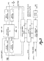
- the power generator in question supplies alternating electric voltage for the correct functioning of a ceramic vibrations emitter, compensating any variations in frequency due to heat problems. It comprises essentially into an aluminium container (Fig.1):
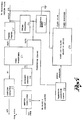
- the power converter (Fig. 3) is made up of a control part, governed by a micro-controller (Block E), and by a power part made up of a IGBT dual pole transistor bridge 16.
- the control part includes a phase controller 17, a section 1 programmable logic device 18, a pulsing transformer control device 19, and a series of pulsing transformers 20.
- the task of the phase controller is to generate the control phases of the power transistors and is piloted by a "sinc" signal coming from the micro-controller and provided to set the operating frequency and voltage of the converter, from a power control signal also coming from the micro-controller and aimed at controlling the phase shift of the converter, and a current limiting signal coming from the transformer (Block C).
- the section 1 programmable logic device 18 receives the control signals in input coming from the phase controller 17, it compares them with an enabling signal coming from the micro-controller and sends them to the drive module of the pulsing transformers 19, which amplify the signals and pilots the pulsing transformers 20. These devices are aimed at creating galvanic insulation between the control part and the power part and to suitably pilot the IGBT transistors.
- the IGBT bipolar transistor bridge 16 is made up of four power transistors which commute the direct current supplied by the power feeder, transforming it into a square wave output voltage, according to a commutation sequence supplied by the phase controller.
- the square wave voltage OUT_PWM is sent both to the power transformer (Block C) and the phase and frequency control device (Block D), together with the piloting signal of the power transistors.
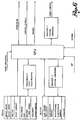
- the power transformer and the tuning adapter transform the signal arriving from the power converter into a signal suitable to pilot the ultrasonic transducer, tuning it to the frequency of the latter.
- the output signal OUT_PWM from the converter passes, before arriving at the power transformer 21, from one part through a coupling capacitor 22 which guarantees the flow of an alternating current to the transformer, and, on the other part, through an ammeter transformer 23, which enables the current supplied by the transformer to be measured and to limit the excess current, connected in series with a resonance inductor 24, provided to tune the resonance frequency of the converter.
- the power transformer generates two outputs OUT1, OUT2, one of which (OUT1) is sent to the tuning adapter 25, the other (OUT2) to a tuner capacitor 26 and to a shunt resistor 27.
- the tuning adapter is therefore the device which, connected to an output connecter, supplies the energy to the ultrasonic emitter.
- the shunt resistor reads the current sent to the ultrasonic emitter and forwards the value of this current to a device 28 named the "transducer connection sensor" which, on the basis of the value of the current, identifies the connection of the ultrasonic transducer and sends an enabling signal to a power and overload measuring device 29.
- the latter is connected to the output of the tuning adapter and includes a resistive divider which sends a power measuring signal suitable to be read by an external instrument and to be sent to the micro-controller to be elaborated and governed.
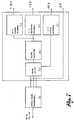
- the phase and frequency control device is made up of two parts: a first part for phase control (Fig. 5) which receives the signals coming from the converter and generates the signals forwarded to the micro-controller in output, and a second part for frequency control (Fog. 5a) which receives signals from the micro-controller and generates an output to the converter.
- the first part includes the following modules:
- the second part of the frequency control includes the following devices:
- the digital frequency synthesizer 35 receives data coming from the micro-controller used to set the output frequency which, on elaboration by a multiplier 36 and a monostable 37 for example, will govern the power converter.
- the micro-controller (Fig. 6) is the calculation center for all the generator, that is, it controls all the circuits and logic and analog signals of the equipment. Its main functions are:
- a service logic feeder completes the power generator /Fig. 7) including, as is well known, the following devices:
Landscapes
- Engineering & Computer Science (AREA)
- Mechanical Engineering (AREA)
- Apparatuses For Generation Of Mechanical Vibrations (AREA)
- Lining Or Joining Of Plastics Or The Like (AREA)
- General Electrical Machinery Utilizing Piezoelectricity, Electrostriction Or Magnetostriction (AREA)
Applications Claiming Priority (2)
| Application Number | Priority Date | Filing Date | Title |
|---|---|---|---|
| ITBS000131 | 2000-12-20 | ||
| IT2000BS000131A IT1315069B1 (it) | 2000-12-22 | 2000-12-22 | Generatore di potenza per saldatura ad ultrasuoni con controllodigitale della frequenza e della potenza |
Publications (1)
| Publication Number | Publication Date |
|---|---|
| EP1216760A2 true EP1216760A2 (fr) | 2002-06-26 |
Family
ID=11440631
Family Applications (1)
| Application Number | Title | Priority Date | Filing Date |
|---|---|---|---|
| EP01870279A Withdrawn EP1216760A2 (fr) | 2000-12-20 | 2001-12-18 | Générateur de puissance pour soudage par ultrasons avec controle digital de la fréquence et de la puissance |
Country Status (2)
| Country | Link |
|---|---|
| EP (1) | EP1216760A2 (fr) |
| IT (1) | IT1315069B1 (fr) |
Cited By (11)
| Publication number | Priority date | Publication date | Assignee | Title |
|---|---|---|---|---|
| EP1772253A3 (fr) * | 2005-10-05 | 2008-03-12 | BRANSON ULTRASCHALL Niederlassung der EMERSON TECHNOLOGIES GmbH & CO. | Dispositif et procédé de soudage par vibration |
| CN100408248C (zh) * | 2005-10-24 | 2008-08-06 | 中国电子科技集团公司第四十五研究所 | 自适应超声波换能器驱动电源 |
| WO2011034294A3 (fr) * | 2009-09-21 | 2011-06-09 | Lg Electronics Inc. | Climatiseur et procédé de commande |
| CN102554450A (zh) * | 2012-01-16 | 2012-07-11 | 雷广伟 | 一种动力电池多层电极超声波机械手焊接设备 |
| DE102011052283A1 (de) * | 2011-07-29 | 2013-01-31 | Herrmann Ultraschalltechnik Gmbh & Co. Kg | Verfahren zur Berechnung der Schwingungsamplitude einer Sonotrode |
| EP2602028A1 (fr) | 2011-12-09 | 2013-06-12 | Sinaptec | Dispositif électronique et système de commande d'applications mettant en oeuvre au moins un transducteur piézoélectronique, électrostrictif ou magnétostrictif |
| WO2014187439A1 (fr) * | 2013-05-24 | 2014-11-27 | Kiefel Gmbh | Oscillateur haute fréquence, système de soudage haute fréquence et procédé de régulation de fréquence au moyen d'un tel oscillateur haute fréquence |
| CN106583910A (zh) * | 2017-01-06 | 2017-04-26 | 深圳市德知拓电源技术有限公司 | 一种超声波焊接电源 |
| IT201900025810A1 (it) * | 2019-12-31 | 2021-07-01 | Sonic Italia S R L | Dispositivo elettronico di pilotaggio e controllo di un gruppo vibrante di un macchinario di saldatura ad ultrasuoni |
| EP3960309A1 (fr) * | 2020-08-31 | 2022-03-02 | Siemens Aktiengesellschaft | Procédé de résonance pour un système de vibrations, convertisseur, unité d'excitation et système de vibrations |
| CN117564434A (zh) * | 2024-01-15 | 2024-02-20 | 钛玛科(北京)工业科技有限公司 | 超声波双滚焊接装置及方法 |
-
2000
- 2000-12-22 IT IT2000BS000131A patent/IT1315069B1/it active
-
2001
- 2001-12-18 EP EP01870279A patent/EP1216760A2/fr not_active Withdrawn
Cited By (25)
| Publication number | Priority date | Publication date | Assignee | Title |
|---|---|---|---|---|
| EP1772253A3 (fr) * | 2005-10-05 | 2008-03-12 | BRANSON ULTRASCHALL Niederlassung der EMERSON TECHNOLOGIES GmbH & CO. | Dispositif et procédé de soudage par vibration |
| CN1943955B (zh) * | 2005-10-05 | 2010-12-15 | 艾默生科技有限公司布兰森超声分公司 | 振动焊接装置及方法 |
| US7964046B2 (en) | 2005-10-05 | 2011-06-21 | Branson Ultraschall Niederlassung Der Emerson Technologies Gmbh & Co. Ohg | Apparatus and method for vibration welding |
| CN100408248C (zh) * | 2005-10-24 | 2008-08-06 | 中国电子科技集团公司第四十五研究所 | 自适应超声波换能器驱动电源 |
| WO2011034294A3 (fr) * | 2009-09-21 | 2011-06-09 | Lg Electronics Inc. | Climatiseur et procédé de commande |
| EP2737287B1 (fr) * | 2011-07-29 | 2021-08-11 | Herrmann Ultraschalltechnik GmbH & Co. KG | Procédé de calcul de l'amplitude de vibration d'une sonotrode |
| DE102011052283A1 (de) * | 2011-07-29 | 2013-01-31 | Herrmann Ultraschalltechnik Gmbh & Co. Kg | Verfahren zur Berechnung der Schwingungsamplitude einer Sonotrode |
| US10067487B2 (en) | 2011-12-09 | 2018-09-04 | Sinaptec | Electronic device and system for controlling applications implementing at least one piezoelectric, electrostrictive or magnetostrictive transducer |
| EP2602028A1 (fr) | 2011-12-09 | 2013-06-12 | Sinaptec | Dispositif électronique et système de commande d'applications mettant en oeuvre au moins un transducteur piézoélectronique, électrostrictif ou magnétostrictif |
| WO2013083925A1 (fr) | 2011-12-09 | 2013-06-13 | Sinaptec | Dispositif electronique et systeme de commande d'applications mettant en œuvre au moins un transducteur piezoelectrique, electrostrictif ou magnetostrictif |
| CN102554450B (zh) * | 2012-01-16 | 2013-12-18 | 广州市科普超声电子技术有限公司 | 一种动力电池多层电极超声波机械手焊接设备 |
| CN102554450A (zh) * | 2012-01-16 | 2012-07-11 | 雷广伟 | 一种动力电池多层电极超声波机械手焊接设备 |
| WO2014187439A1 (fr) * | 2013-05-24 | 2014-11-27 | Kiefel Gmbh | Oscillateur haute fréquence, système de soudage haute fréquence et procédé de régulation de fréquence au moyen d'un tel oscillateur haute fréquence |
| US10239261B2 (en) | 2013-05-24 | 2019-03-26 | Kiefel Gmbh | High frequency oscillator, high frequency welding system and method for controlling the frequency using said type of high frequency oscillator |
| CN105247780B (zh) * | 2013-05-24 | 2020-08-28 | 凯孚尔有限公司 | 高频振荡器、高频焊接设备和利用该高频振荡器来调节频率的方法 |
| CN105247780A (zh) * | 2013-05-24 | 2016-01-13 | 凯孚尔有限公司 | 高频振荡器、高频焊接设备和利用该高频振荡器来调节频率的方法 |
| CN106583910A (zh) * | 2017-01-06 | 2017-04-26 | 深圳市德知拓电源技术有限公司 | 一种超声波焊接电源 |
| IT201900025810A1 (it) * | 2019-12-31 | 2021-07-01 | Sonic Italia S R L | Dispositivo elettronico di pilotaggio e controllo di un gruppo vibrante di un macchinario di saldatura ad ultrasuoni |
| EP3845317A1 (fr) * | 2019-12-31 | 2021-07-07 | Sonic Italia S.r.l. | Appareil électronique pour alimenter et contrôler une unité de vibration d'une machine de souder à ultrasons |
| EP3960309A1 (fr) * | 2020-08-31 | 2022-03-02 | Siemens Aktiengesellschaft | Procédé de résonance pour un système de vibrations, convertisseur, unité d'excitation et système de vibrations |
| WO2022043108A1 (fr) * | 2020-08-31 | 2022-03-03 | Siemens Aktiengesellschaft | Procédé de résonance pour un système de vibration, convertisseur, unité d'excitation et système de vibration |
| CN116033972A (zh) * | 2020-08-31 | 2023-04-28 | 西门子股份公司 | 振动系统的谐振方法、转换器、激励单元及振动系统 |
| US12194496B2 (en) | 2020-08-31 | 2025-01-14 | Siemens Aktiengesellschaft | Resonance method for a vibration system, a converter, an excitation unit and the vibration system |
| CN117564434A (zh) * | 2024-01-15 | 2024-02-20 | 钛玛科(北京)工业科技有限公司 | 超声波双滚焊接装置及方法 |
| CN117564434B (zh) * | 2024-01-15 | 2024-04-30 | 钛玛科(北京)工业科技有限公司 | 超声波双滚焊接装置及方法 |
Also Published As
| Publication number | Publication date |
|---|---|
| ITBS20000131A1 (it) | 2002-06-20 |
| ITBS20000131A0 (it) | 2000-12-22 |
| IT1315069B1 (it) | 2003-01-27 |
Similar Documents
| Publication | Publication Date | Title |
|---|---|---|
| EP1216760A2 (fr) | Générateur de puissance pour soudage par ultrasons avec controle digital de la fréquence et de la puissance | |
| US5451161A (en) | Oscillating circuit for ultrasonic dental scaler | |
| US5730594A (en) | Ultrasonic dental scaler selectively tunable either manually or automatically | |
| US6255635B1 (en) | System and method for providing RF power to a load | |
| CA2021395C (fr) | Generateur d'ultrasons a convertisseur piezoelectrique | |
| US4445063A (en) | Energizing circuit for ultrasonic transducer | |
| JP2763319B2 (ja) | 高周波電力発生装置 | |
| EP0404150B1 (fr) | Circuit pour adapter la fréquence de résonance d'un circuit résonant d'antenne à la fréquence de sortie d'un étage de sortie d'un émetteur | |
| GB2181030A (en) | High-frequency induction heating systems and methods of protecting circuits thereof | |
| JPH05504507A (ja) | 高周波数振動工具を送るための装置 | |
| US4389601A (en) | Power supply having automatic frequency control for ultrasonic bonding | |
| US4583529A (en) | High efficiency high frequency power oscillator | |
| US4680506A (en) | Inverter-type microwave oven power supply | |
| GB2367196A (en) | Microwave oven having a switching power supply Microwave oven having a switching power supply | |
| CN102598849B (zh) | 具有至少两个加热感应器的灶台 | |
| EP0233066A2 (fr) | Dispositif de tamisage | |
| GB2085243A (en) | Apparatus for driving a heating load circuit | |
| US7715167B2 (en) | Apparatus and method for controlling excitation frequency of magnetostrictive transducer | |
| CN101369778A (zh) | 开关电源及其供电方法 | |
| EP0125588A1 (fr) | Régulation de tension d'une charge pour un onduleur à circuit résonant | |
| WO2000067658A1 (fr) | Detartreur ultrasonore avec amplitude adaptative | |
| RU2406275C2 (ru) | Электрическая схема, зажимное крепление и способ управления | |
| RU2000124166A (ru) | Схема импульсного блока питания | |
| US11894689B2 (en) | Power supply system and vibrating processing apparatus | |
| CN112928899A (zh) | 具有自适应反馈控制回路的电源单元 |
Legal Events
| Date | Code | Title | Description |
|---|---|---|---|
| PUAI | Public reference made under article 153(3) epc to a published international application that has entered the european phase |
Free format text: ORIGINAL CODE: 0009012 |
|
| AK | Designated contracting states |
Kind code of ref document: A2 Designated state(s): AT BE CH CY DE DK ES FI FR GB GR IE IT LI LU MC NL PT SE TR |
|
| AX | Request for extension of the european patent |
Free format text: AL;LT;LV;MK;RO;SI |
|
| STAA | Information on the status of an ep patent application or granted ep patent |
Free format text: STATUS: THE APPLICATION IS DEEMED TO BE WITHDRAWN |
|
| 18D | Application deemed to be withdrawn |
Effective date: 20040701 |