EP1216856B2 - Attelage de remorque pour un véhicule de travail - Google Patents
Attelage de remorque pour un véhicule de travail Download PDFInfo
- Publication number
- EP1216856B2 EP1216856B2 EP01130371A EP01130371A EP1216856B2 EP 1216856 B2 EP1216856 B2 EP 1216856B2 EP 01130371 A EP01130371 A EP 01130371A EP 01130371 A EP01130371 A EP 01130371A EP 1216856 B2 EP1216856 B2 EP 1216856B2
- Authority
- EP
- European Patent Office
- Prior art keywords
- coupling
- ball
- holding
- trailer
- trailer coupling
- Prior art date
- Legal status (The legal status is an assumption and is not a legal conclusion. Google has not performed a legal analysis and makes no representation as to the accuracy of the status listed.)
- Expired - Lifetime
Links
Images


Classifications
-
- B—PERFORMING OPERATIONS; TRANSPORTING
- B60—VEHICLES IN GENERAL
- B60D—VEHICLE CONNECTIONS
- B60D1/00—Traction couplings; Hitches; Draw-gear; Towing devices
- B60D1/58—Auxiliary devices
- B60D1/583—Holding-down means, e.g. holding-down retainers
-
- A—HUMAN NECESSITIES
- A01—AGRICULTURE; FORESTRY; ANIMAL HUSBANDRY; HUNTING; TRAPPING; FISHING
- A01B—SOIL WORKING IN AGRICULTURE OR FORESTRY; PARTS, DETAILS, OR ACCESSORIES OF AGRICULTURAL MACHINES OR IMPLEMENTS, IN GENERAL
- A01B59/00—Devices specially adapted for connection between animals or tractors and agricultural machines or implements
- A01B59/04—Devices specially adapted for connection between animals or tractors and agricultural machines or implements for machines pulled or pushed by a tractor
- A01B59/042—Devices specially adapted for connection between animals or tractors and agricultural machines or implements for machines pulled or pushed by a tractor having pulling means arranged on the rear part of the tractor
-
- B—PERFORMING OPERATIONS; TRANSPORTING
- B60—VEHICLES IN GENERAL
- B60D—VEHICLE CONNECTIONS
- B60D1/00—Traction couplings; Hitches; Draw-gear; Towing devices
- B60D1/01—Traction couplings or hitches characterised by their type
- B60D1/06—Ball-and-socket hitches
-
- B—PERFORMING OPERATIONS; TRANSPORTING
- B60—VEHICLES IN GENERAL
- B60D—VEHICLE CONNECTIONS
- B60D1/00—Traction couplings; Hitches; Draw-gear; Towing devices
- B60D1/01—Traction couplings or hitches characterised by their type
- B60D1/06—Ball-and-socket hitches
- B60D1/065—Ball-and-socket hitches characterised by the hitch mechanism
-
- B—PERFORMING OPERATIONS; TRANSPORTING
- B60—VEHICLES IN GENERAL
- B60D—VEHICLE CONNECTIONS
- B60D1/00—Traction couplings; Hitches; Draw-gear; Towing devices
- B60D1/24—Traction couplings; Hitches; Draw-gear; Towing devices characterised by arrangements for particular functions
- B60D1/42—Traction couplings; Hitches; Draw-gear; Towing devices characterised by arrangements for particular functions for being adjustable
- B60D1/46—Traction couplings; Hitches; Draw-gear; Towing devices characterised by arrangements for particular functions for being adjustable vertically
- B60D1/465—Traction couplings; Hitches; Draw-gear; Towing devices characterised by arrangements for particular functions for being adjustable vertically comprising a lifting mechanism, e.g. for coupling while lifting
-
- B—PERFORMING OPERATIONS; TRANSPORTING
- B60—VEHICLES IN GENERAL
- B60D—VEHICLE CONNECTIONS
- B60D1/00—Traction couplings; Hitches; Draw-gear; Towing devices
- B60D1/48—Traction couplings; Hitches; Draw-gear; Towing devices characterised by the mounting
- B60D1/54—Traction couplings; Hitches; Draw-gear; Towing devices characterised by the mounting collapsible or retractable when not in use, e.g. hide-away hitches
Definitions
- the invention relates to a trailer system for an agricultural or industrial vehicle with a vertically pivotable between an upper transport position and a lowered position hinged to the vehicle body frame part.
- the free, pivotable end of the frame part receives a projecting, directly or indirectly guided by the frame part and lockable in at least one vehicle longitudinal position coupling part.
- Such attachment systems are commonly referred to as pick-up hitch.
- Such a trailer system according to the preamble is by the EP-A-0 695 655 has become known, which refers to an immediate determination between a designated traction element coupling part and the vehicle body.
- the tension element described therein is either designed as a conventional drawbar or it contains a conventional upstanding hitch hook (ISO 6489-1), which serves as a pulling or carrying device for the trailer eye of an attached device.
- the load on the drawbar or hitch hook is limited and does not always meet the requirements of the practice.
- the vertical load on the Hitch hook must not exceed 30 kN (approx. 3 t).
- This support load limits the load capacity of the vehicle during intensive transport work, although a higher load would in principle be possible due to the low-lying position of the trailer attachment system on the tractor.
- a relatively high wear is generated by the high vertical support loads in the support surface between the hitch hook and the trailer lug, which can not be limited to satisfactory values due to the existing geometry of the components, which allow a relative movement to each other in the engaged state.
- the coupling carrier is rigidly attached to the coupling ball on the vehicle chassis.
- this coupling device the coupling process is difficult because, on the one hand, the operator can not see the coupling point from the driver's cab. It is therefore an assistant required, or the operator must leave the cab several times for coupling.
- a lifting device for the drawbar of the trailer is needed to bring it to the height of the coupling ball.
- the object underlying the invention is seen to provide a trailer system of the type mentioned, by which the aforementioned problems are overcome.
- the attachment system should be suitable to accommodate higher than usual support loads.
- wear phenomena should be minimized and the coupling process should be facilitated.
- the attachment system includes a vertically in the vertical direction between an upper transport position and a lowered position hinged to the vehicle body frame part.
- the free, pivotable end of the frame part receives a projecting, directly or indirectly guided by the frame part and lockable in at least one vehicle longitudinal position coupling part.
- the coupling part contains a coupling ball.
- the bearing surfaces can be considerably larger than known solutions, so that an improvement of the function (increase of the permissible support loads) is achieved.
- the clutch parts serving coupling parts - coupling ball and counter-pan of the device to be coupled - can be coordinated so that forms a substantially backlash-free connection.
- the time stability improvement of the wear behavior
- the coupling ball is not attached to a fixed predetermined location on the vehicle chassis, but on a height and length adjustable attachment system.
- This makes it possible to set the vehicle-mounted dome point to the respective height of the hitch for coupling the hitch of a trailer drawbar, in particular lowered from its lockable base or transport position, can be. Tools for lifting the trailer drawbar are not required.
- the dome point in the vehicle longitudinal direction can be extended so far that it is visible from the driver's seat of the vehicle platform, which considerably simplifies the dome operation and makes the involvement of a second person superfluous.
- the advantages of a movable pick-up hitch are combined with those of a ball coupling.
- the coupling ball in the upper region of the outermost free end of the coupling part.
- the extending in the vehicle longitudinal direction free end of the coupling part can extend in an upwardly curved arc and end in a coupling ball.
- a preferred embodiment of the invention provides that a holding device is attached to the coupling part, which serves to lock the coupling part on the vehicle body.
- the locking can take place on a locking device fastened directly to the vehicle body or on a locking device which is mounted on a component fastened to the vehicle body.
- the holding device is a substantially projecting from the coupling part up tab, which has a horizontal transverse recess.
- the transverse recess serves to receive a locking bolt, by means of which the attachment system, in particular the coupling part and the frame part, can be locked in the upper transport position relative to the vehicle body.
- the coupling part is formed with the coupling ball and optionally with the holding device as a one-piece forging, which is able to absorb high tensile and compressive forces.
- said parts may be connected to each other inseparably in other ways.
- a holding-down device which secures a coupling device mounted on the coupling ball, provided that the attachment system is in the transport position.
- the hold-down is expediently two protruding tabs which are aligned substantially parallel to one another and each have a transverse recess which corresponds to the transverse recess of the tab of the holding device, provided that the frame part and the holding device assume the transport position.
- the tabs can accommodate locking bolts.
- the attachment system shown essentially consists of an upper frame member 10, a lower frame member 12, a guide member 14 and a coupling member 16.
- the upper frame member 10 includes mounting plates 18, 20 with mounting holes, the rigid attachment of the upper frame member 10 to a Schuachsdifferentialgereheatuse not shown serve a tractor, with the mounting plate 20 is located at the rear end of the tractor. Because of the rigid attachment, the upper frame member 10 may be considered part of the vehicle body.
- the rear vertically oriented mounting plate 20 carries a hold-down 22, which consists essentially of two mutually parallel and vertically aligned, rearwardly projecting hold-down tabs 24, 26.
- the covered by a stiffening plate 27 hold-down tabs 24, 26 each include a transverse bore 28.
- the transverse bores 28 correspond to each other and serve to receive a locking pin, not shown, a locking device 30.
- the locking device 30 is in accordance with Fig. 1 right hold-down tab 26 screwed. It is, for example, a locking device whose training and operation in the EP-A-0 695 655 has been described.
- a transverse to the vehicle longitudinal direction and horizontally oriented pivot axis 32 is formed, on which the front end of the lower frame member 12 is articulated.
- two bolts 34 oriented transversely outwards and in the horizontal direction are fastened to the lower frame part. At these bolts 34 can fix the ends of a lifting link, not shown, through which the lower frame member 12 can pivot about the pivot axis 32 to raise or lower the rear end thereof.
- the lower frame part 12 is formed in the manner of a cassette and includes a substantially rectangular channel in which the guide member 14 is guided displaceably in the vehicle longitudinal direction.
- a hydraulic cylinder for displacement of the guide member 14, is used, one end of which acts on the pivot axis 32 and the other end on the guide member 14.
- the coupling member 16 by at least one screw, not shown, which extends through a recess 35 of the coupling part 16, attached.
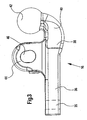
- the coupling part 16 goes out Fig. 3 out. It includes a front portion 36 which is formed substantially rectangular in shape and in a correspondingly shaped channel in the guide member 14 can be inserted.
- the rear end 38 of the rectangular portion 36 merges into an arcuate ball neck 40, the upper end of which carries a coupling ball 42 projecting upwards and rearwards over the rest of the attachment system.
- the coupling ball 42 is thus at the extreme rear end of the coupling part 16.
- the coupling part 16 From the central region of the coupling part 16 is formed as a tab 44 holding device upwards, which has a transverse, horizontal transverse recess 46.
- the transverse recess 46 of the tab 44 is aligned with the transverse bores 28 in the hold-down tabs 24, 26, so that a locking bolt of the locking device 30 is inserted and the coupling part 16 can be set directly opposite the vehicle-fixed upper frame part 10.
- the recess has a slightly oval cross-section, which is slightly narrower at the top than below, whereby the locking and finding a defined transport position is facilitated.
- the coupling part 16 is a forged part and formed integrally with the coupling ball 42 and the tab 44.
- the coupling ball 42 serves to receive a coupling device, not shown, which includes a ball socket, which is mounted, for example, at the front free end of a trailer drawbar.
- a coupling device not shown
- the hold-down tabs 24, 26 have in their rear, lower region a circular shape 48, which is adapted to the spherical surface of the coupling ball 42.
- the hold-down tabs 24, 26 thus ensure, whenever the attachment system assumes its upper transport position, a ball socket received by the coupling ball 42. If, after loosening the locking device 30, the suspension system is pivoted downwards out of its transport position, the ball socket exits from the area of influence of the hold-down tabs 24, 26, so that it can lift itself off the coupling ball 42 and release it.
Landscapes
- Engineering & Computer Science (AREA)
- Mechanical Engineering (AREA)
- Transportation (AREA)
- Life Sciences & Earth Sciences (AREA)
- Zoology (AREA)
- Soil Sciences (AREA)
- Environmental Sciences (AREA)
- Agricultural Machines (AREA)
- Lifting Devices For Agricultural Implements (AREA)
- Vehicle Cleaning, Maintenance, Repair, Refitting, And Outriggers (AREA)
Claims (7)
- Système d'attelage pour un véhicule agricole ou industriel comprenant une partie de châssis (12) articulée à l'arrière du véhicule (10) de manière à pouvoir pivoter dans une direction verticale entre une position de transport supérieure et une position abaissée, dont l'extrémité libre pivotante reçoit une partie d'accouplement (16) saillante, guidée directement ou indirectement dans la partie de châssis (12) et pouvant être bloquée dans au moins une position longitudinale du véhicule,
caractérisé en ce que
la partie d'accouplement (16) comprend une boule d'accouplement (42) et en ce qu'au moins un serre-flan (22) avec des pattes de serre-flan (24, 26) pour la fixation d'un dispositif d'accouplement monté sur la boule d'accouplement (42) est disposé sur l'arrière du véhicule, de manière directe ou indirecte, de telle sorte qu'une cavité sphérique reçue par une boule d'accouplement (42) soit sécurisée lorsque le système d'attelage se trouve dans sa position de transport supérieure, les pattes de serre-flan (24, 26) présentant, dans une région arrière inférieure, une forme circulaire (48) qui est adaptée à la surface sphérique de la boule d'accouplement (42). - Système d'attelage selon la revendication 1,
caractérisé en ce que
la boule d'accouplement (42) s'étend vers le haut à l'extrémité libre extérieure de la partie d'accouplement (16). - Système d'attelage selon la revendication 1 ou 2,
caractérisé en ce que
la partie d'accouplement (16) et la boule d'accouplement (42) sont réalisées d'une seule pièce et sont connectées l'une à l'autre de manière non amovible. - Système d'attelage selon l'une quelconque des revendications 1 à 3,
caractérisé en ce
qu'un dispositif de retenue (44) est monté sur la partie d'accouplement (16), lequel sert à bloquer directement ou indirectement la partie d'accouplement (16) sur l'arrière du véhicule (10). - Système d'attelage selon l'une quelconque des revendications 1 à 4,
caractérisé en ce que
la partie d'accouplement (16) est réalisée avec la boule d'accouplement (42) et éventuellement avec le dispositif de retenue (44) sous forme de pièce forgée. - Système d'attelage selon la revendication 4 ou 5,
caractérisé en ce que
le dispositif de retenue est essentiellement une patte saillant vers le haut (44), avec un évidement transversal (46) orienté horizontalement. - Système d'attelage selon la revendication 1,
caractérisé en ce que
l'on utilise comme serre-flans (22) deux pattes de serre-flan (24, 26) saillantes orientées essentiellement parallèlement l'une à l'autre, qui présentent chacune un évidement transversal (28), qui correspond à l'évidement transversal (46) de la patte (44) du dispositif de retenue, lorsque la partie de châssis (12) et le dispositif de retenue adoptent la position de transport.
Priority Applications (1)
| Application Number | Priority Date | Filing Date | Title |
|---|---|---|---|
| EP05105324A EP1574364A3 (fr) | 2000-12-23 | 2001-12-20 | Attelage de remorque pour un véhicule de travail |
Applications Claiming Priority (2)
| Application Number | Priority Date | Filing Date | Title |
|---|---|---|---|
| DE10065161 | 2000-12-23 | ||
| DE10065161A DE10065161A1 (de) | 2000-12-23 | 2000-12-23 | Anhängevorrichtung für ein Arbeitsfahrzeug |
Related Child Applications (2)
| Application Number | Title | Priority Date | Filing Date |
|---|---|---|---|
| EP05105324A Division EP1574364A3 (fr) | 2000-12-23 | 2001-12-20 | Attelage de remorque pour un véhicule de travail |
| EP05105324.7 Division-Into | 2005-06-16 |
Publications (4)
| Publication Number | Publication Date |
|---|---|
| EP1216856A2 EP1216856A2 (fr) | 2002-06-26 |
| EP1216856A3 EP1216856A3 (fr) | 2002-11-27 |
| EP1216856B1 EP1216856B1 (fr) | 2005-08-24 |
| EP1216856B2 true EP1216856B2 (fr) | 2009-05-06 |
Family
ID=7669095
Family Applications (2)
| Application Number | Title | Priority Date | Filing Date |
|---|---|---|---|
| EP01130371A Expired - Lifetime EP1216856B2 (fr) | 2000-12-23 | 2001-12-20 | Attelage de remorque pour un véhicule de travail |
| EP05105324A Withdrawn EP1574364A3 (fr) | 2000-12-23 | 2001-12-20 | Attelage de remorque pour un véhicule de travail |
Family Applications After (1)
| Application Number | Title | Priority Date | Filing Date |
|---|---|---|---|
| EP05105324A Withdrawn EP1574364A3 (fr) | 2000-12-23 | 2001-12-20 | Attelage de remorque pour un véhicule de travail |
Country Status (3)
| Country | Link |
|---|---|
| EP (2) | EP1216856B2 (fr) |
| AT (1) | ATE302697T1 (fr) |
| DE (2) | DE10065161A1 (fr) |
Families Citing this family (19)
| Publication number | Priority date | Publication date | Assignee | Title |
|---|---|---|---|---|
| AT412712B (de) * | 2002-12-20 | 2005-06-27 | Josef Ing Scharmueller | Hubkupplung |
| AT412630B (de) * | 2003-02-12 | 2005-05-25 | Josef Ing Scharmueller | Kupplungsvorrichtung und verfahren zum schliessen einer kupplungsvorrichtung |
| RU2245258C1 (ru) * | 2003-07-17 | 2005-01-27 | Общество с ограниченной ответственностью "ТехноМастер" | Тягово-сцепное устройство для легкового автомобиля |
| AT413970B (de) * | 2004-09-24 | 2006-07-15 | Josef Ing Scharmueller | Kupplung |
| DE102005019362A1 (de) * | 2005-04-26 | 2006-11-02 | Deere & Company, Moline | Elektrische Schnittstellenvorrichtung zum Übertragen elektrischer Energie zwischen einem Fahrzeug und einem an das Fahrzeug ankoppelbaren Arbeitsgerät |
| AT503295B1 (de) * | 2006-06-16 | 2007-09-15 | Scharmueller Josef Ing | Hubkupplung |
| ITMO20070108A1 (it) | 2007-03-29 | 2008-09-30 | Cbm Spa | Dispositivo di traino per un veicolo agricolo o industriale. |
| DE102007036429A1 (de) | 2007-08-02 | 2009-02-05 | Deere & Company, Moline | Steuerungssystem und Verfahren zum Betreiben eines Steuerungssystems zum Lenken eines an ein landwirtschafliches Nutzfahrzeug anagekoppelten Anbaugeräts |
| CN101596847B (zh) * | 2009-06-24 | 2011-09-14 | 叶培玉 | 球头朝上牵引器及其牵引方法 |
| EP3379222B1 (fr) | 2017-03-22 | 2020-12-30 | Methode Electronics Malta Ltd. | Ensemble de capteur à base magnétoélastique |
| DE102017214354B3 (de) | 2017-04-24 | 2018-09-27 | Deere & Company | Landwirtschaftliches Arbeitsfahrzeug mit Bodeneingriffsmitteln zur Übertragung von Querkräften |
| US11084342B2 (en) | 2018-02-27 | 2021-08-10 | Methode Electronics, Inc. | Towing systems and methods using magnetic field sensing |
| US11221262B2 (en) | 2018-02-27 | 2022-01-11 | Methode Electronics, Inc. | Towing systems and methods using magnetic field sensing |
| US10670479B2 (en) | 2018-02-27 | 2020-06-02 | Methode Electronics, Inc. | Towing systems and methods using magnetic field sensing |
| US11491832B2 (en) | 2018-02-27 | 2022-11-08 | Methode Electronics, Inc. | Towing systems and methods using magnetic field sensing |
| US11135882B2 (en) | 2018-02-27 | 2021-10-05 | Methode Electronics, Inc. | Towing systems and methods using magnetic field sensing |
| DE102019204473A1 (de) | 2019-03-29 | 2020-10-01 | Deere & Company | Anhängevorrichtung für ein landwirtschaftliches Fahrzeug |
| ES2788685B2 (es) * | 2019-04-22 | 2021-10-05 | Efitrans Efficient Logistics S L | Sistema de union entre remolque y camion |
| DE102024102279A1 (de) * | 2024-01-26 | 2025-07-31 | Deere & Company | Kupplungsanordnung für einen landwirtschaftlichen Traktor |
Family Cites Families (14)
| Publication number | Priority date | Publication date | Assignee | Title |
|---|---|---|---|---|
| US2966369A (en) * | 1959-11-17 | 1960-12-27 | Jr Herman J Paul | Trailer hitch |
| FR2201815B1 (fr) * | 1972-10-11 | 1977-01-14 | Remoise Mecano Soudure | |
| US3827724A (en) * | 1973-02-16 | 1974-08-06 | Deere & Co | Coupling device |
| US3826517A (en) * | 1973-02-16 | 1974-07-30 | Deere & Co | Coupling device |
| GB2009579A (en) * | 1977-09-15 | 1979-06-20 | Whitton & Brown Ltd | Improvements in or Relating to Pick-Up Hitches |
| US4199167A (en) * | 1978-08-23 | 1980-04-22 | Points Warren D | Insertable hitch for tractors |
| US4340240A (en) * | 1980-02-04 | 1982-07-20 | Anderson Ernest L | Three point hitch adaptor for a tractor |
| US4434996A (en) * | 1982-04-23 | 1984-03-06 | Wallace Dean L | Towing hitch construction |
| US4568098A (en) * | 1983-07-20 | 1986-02-04 | Landry Jr Ernest A | Trailer hitch |
| FR2592339B1 (fr) * | 1985-12-30 | 1989-06-09 | Cosnet Pascal | Attelage oscillant, adaptable notamment sur un tracteur et utilisation de cet attelage |
| US5088753A (en) * | 1991-04-12 | 1992-02-18 | Clarence Granata | Three-point hitch which is convertible to a ball hitch |
| EP0695655B1 (fr) * | 1994-08-03 | 1998-04-01 | Deere & Company | Système de traction et dispositif de blocage |
| IES940924A2 (en) * | 1994-11-25 | 1996-04-03 | Patrick Mccormick | Hitch Assembly |
| AT406849B (de) * | 1999-04-30 | 2000-09-25 | Scharmueller Josef Ing | Kupplungsvorrichtung zwischen einem zugfahrzeug, insbesondere einem ackerschlepper, und einem anhänger |
-
2000
- 2000-12-23 DE DE10065161A patent/DE10065161A1/de not_active Withdrawn
-
2001
- 2001-12-20 EP EP01130371A patent/EP1216856B2/fr not_active Expired - Lifetime
- 2001-12-20 AT AT01130371T patent/ATE302697T1/de active
- 2001-12-20 EP EP05105324A patent/EP1574364A3/fr not_active Withdrawn
- 2001-12-20 DE DE50107191T patent/DE50107191D1/de not_active Expired - Lifetime
Non-Patent Citations (1)
| Title |
|---|
| "DESIGNS AND SPECIFICATIONS FOR A STANDART TRAILER & HITCH FOR LABOUR-BASED WORKS", ASIST INFORMATION SERVICES, 1997, NAIROBI KENYA, pages 1 - 37 † |
Also Published As
| Publication number | Publication date |
|---|---|
| DE10065161A1 (de) | 2002-07-04 |
| EP1574364A2 (fr) | 2005-09-14 |
| EP1216856B1 (fr) | 2005-08-24 |
| ATE302697T1 (de) | 2005-09-15 |
| DE50107191D1 (de) | 2005-09-29 |
| EP1574364A3 (fr) | 2005-11-23 |
| EP1216856A2 (fr) | 2002-06-26 |
| EP1216856A3 (fr) | 2002-11-27 |
Similar Documents
| Publication | Publication Date | Title |
|---|---|---|
| EP1216856B2 (fr) | Attelage de remorque pour un véhicule de travail | |
| DE69226196T2 (de) | Fahrerhaus fuer eine planierraupe | |
| DE10231221A1 (de) | Anhängezugvorrichtung | |
| EP1308075A1 (fr) | Aide pour accoupler un outil ou une remorque avec un timon à un tracteur | |
| DE60214433T2 (de) | Zughakensystem | |
| DE4235797A1 (de) | Kraftfahrzeug mit Hubgerüst | |
| DE102007045912A1 (de) | Landwirtschaftliches Fahrzeug | |
| EP3351074B1 (fr) | Élément rapporté avec dispositif d'accouplement et attelage composé de l'élément rapporté et d'un véhicule | |
| EP2457752B1 (fr) | Dispositif d'embrayage et dispositif d'attelage pour véhicules tracteurs | |
| DE10052051A1 (de) | Vorrichtung zum Kuppeln eines Fahrzeugs mit einem Geät oder Anhänger | |
| EP1710100B1 (fr) | Accouplement pour charges lourdes | |
| EP1236590A1 (fr) | Attelage de remorque | |
| DE602006000600T2 (de) | Anhängerkupplung | |
| DE102010053083A1 (de) | Sattelkupplung mit einstellbarer Höhe | |
| DE2613718A1 (de) | An einem traktor anbringbare baueinheit | |
| DE19847984C2 (de) | Leiterrahmen | |
| DE102004004082A1 (de) | Anhängesystem zur Verbindung eines Zugfahrzeuges mit einem Anhänger | |
| DE102012015556A1 (de) | Sattelauflieger mit einer Kippermulde | |
| DE2265144A1 (de) | Anhaengekupplung | |
| EP3666558B1 (fr) | Attelage de remorque | |
| DE102010049259A1 (de) | Zugdeichsel | |
| DE102007006265A1 (de) | Sattelzugmaschine eines Sattelkraftwagens | |
| DE10317126B4 (de) | Vorrichtung zur lösbaren Verbindung von zwei in Reihe angeordneten Fahrzeugelementen eines Fahrzeugs | |
| AT409619B (de) | Lastkraftwagen mit einem am vorderen ende des rahmens angebauten geräteträger | |
| DE102006062199B4 (de) | Fahrgestell für landwirtschaftliche Anbaugeräte |
Legal Events
| Date | Code | Title | Description |
|---|---|---|---|
| PUAI | Public reference made under article 153(3) epc to a published international application that has entered the european phase |
Free format text: ORIGINAL CODE: 0009012 |
|
| AK | Designated contracting states |
Kind code of ref document: A2 Designated state(s): AT BE CH CY DE DK ES FI FR GB GR IE IT LI LU MC NL PT SE TR |
|
| AX | Request for extension of the european patent |
Free format text: AL;LT;LV;MK;RO;SI |
|
| PUAL | Search report despatched |
Free format text: ORIGINAL CODE: 0009013 |
|
| AK | Designated contracting states |
Kind code of ref document: A3 Designated state(s): AT BE CH CY DE DK ES FI FR GB GR IE IT LI LU MC NL PT SE TR |
|
| AX | Request for extension of the european patent |
Free format text: AL;LT;LV;MK;RO;SI |
|
| 17P | Request for examination filed |
Effective date: 20030527 |
|
| AKX | Designation fees paid |
Designated state(s): AT BE CH CY DE DK ES FI FR GB GR IE IT LI LU MC NL PT SE TR |
|
| 17Q | First examination report despatched |
Effective date: 20040116 |
|
| GRAP | Despatch of communication of intention to grant a patent |
Free format text: ORIGINAL CODE: EPIDOSNIGR1 |
|
| GRAS | Grant fee paid |
Free format text: ORIGINAL CODE: EPIDOSNIGR3 |
|
| GRAA | (expected) grant |
Free format text: ORIGINAL CODE: 0009210 |
|
| AK | Designated contracting states |
Kind code of ref document: B1 Designated state(s): AT BE CH CY DE DK ES FI FR GB GR IE IT LI LU MC NL PT SE TR |
|
| PG25 | Lapsed in a contracting state [announced via postgrant information from national office to epo] |
Ref country code: TR Free format text: LAPSE BECAUSE OF FAILURE TO SUBMIT A TRANSLATION OF THE DESCRIPTION OR TO PAY THE FEE WITHIN THE PRESCRIBED TIME-LIMIT Effective date: 20050824 Ref country code: NL Free format text: LAPSE BECAUSE OF FAILURE TO SUBMIT A TRANSLATION OF THE DESCRIPTION OR TO PAY THE FEE WITHIN THE PRESCRIBED TIME-LIMIT Effective date: 20050824 |
|
| REG | Reference to a national code |
Ref country code: GB Ref legal event code: FG4D Free format text: NOT ENGLISH |
|
| REG | Reference to a national code |
Ref country code: CH Ref legal event code: EP |
|
| REG | Reference to a national code |
Ref country code: IE Ref legal event code: FG4D Free format text: LANGUAGE OF EP DOCUMENT: GERMAN |
|
| REF | Corresponds to: |
Ref document number: 50107191 Country of ref document: DE Date of ref document: 20050929 Kind code of ref document: P |
|
| GBT | Gb: translation of ep patent filed (gb section 77(6)(a)/1977) |
Effective date: 20050917 |
|
| PG25 | Lapsed in a contracting state [announced via postgrant information from national office to epo] |
Ref country code: SE Free format text: LAPSE BECAUSE OF FAILURE TO SUBMIT A TRANSLATION OF THE DESCRIPTION OR TO PAY THE FEE WITHIN THE PRESCRIBED TIME-LIMIT Effective date: 20051124 Ref country code: DK Free format text: LAPSE BECAUSE OF FAILURE TO SUBMIT A TRANSLATION OF THE DESCRIPTION OR TO PAY THE FEE WITHIN THE PRESCRIBED TIME-LIMIT Effective date: 20051124 Ref country code: GR Free format text: LAPSE BECAUSE OF FAILURE TO SUBMIT A TRANSLATION OF THE DESCRIPTION OR TO PAY THE FEE WITHIN THE PRESCRIBED TIME-LIMIT Effective date: 20051124 |
|
| PG25 | Lapsed in a contracting state [announced via postgrant information from national office to epo] |
Ref country code: ES Free format text: LAPSE BECAUSE OF FAILURE TO SUBMIT A TRANSLATION OF THE DESCRIPTION OR TO PAY THE FEE WITHIN THE PRESCRIBED TIME-LIMIT Effective date: 20051205 |
|
| PG25 | Lapsed in a contracting state [announced via postgrant information from national office to epo] |
Ref country code: CY Free format text: LAPSE BECAUSE OF FAILURE TO SUBMIT A TRANSLATION OF THE DESCRIPTION OR TO PAY THE FEE WITHIN THE PRESCRIBED TIME-LIMIT Effective date: 20051220 |
|
| PG25 | Lapsed in a contracting state [announced via postgrant information from national office to epo] |
Ref country code: CH Free format text: LAPSE BECAUSE OF NON-PAYMENT OF DUE FEES Effective date: 20051231 Ref country code: LI Free format text: LAPSE BECAUSE OF NON-PAYMENT OF DUE FEES Effective date: 20051231 Ref country code: LU Free format text: LAPSE BECAUSE OF NON-PAYMENT OF DUE FEES Effective date: 20051231 Ref country code: MC Free format text: LAPSE BECAUSE OF NON-PAYMENT OF DUE FEES Effective date: 20051231 Ref country code: BE Free format text: LAPSE BECAUSE OF NON-PAYMENT OF DUE FEES Effective date: 20051231 |
|
| PG25 | Lapsed in a contracting state [announced via postgrant information from national office to epo] |
Ref country code: PT Free format text: LAPSE BECAUSE OF FAILURE TO SUBMIT A TRANSLATION OF THE DESCRIPTION OR TO PAY THE FEE WITHIN THE PRESCRIBED TIME-LIMIT Effective date: 20060124 |
|
| PLBI | Opposition filed |
Free format text: ORIGINAL CODE: 0009260 |
|
| NLV1 | Nl: lapsed or annulled due to failure to fulfill the requirements of art. 29p and 29m of the patents act | ||
| 26 | Opposition filed |
Opponent name: SCHARMUELLER GESELLSCHAFT M.B.H. & CO.KG Effective date: 20060123 |
|
| ET | Fr: translation filed | ||
| PLAX | Notice of opposition and request to file observation + time limit sent |
Free format text: ORIGINAL CODE: EPIDOSNOBS2 |
|
| REG | Reference to a national code |
Ref country code: CH Ref legal event code: PL |
|
| PLAF | Information modified related to communication of a notice of opposition and request to file observations + time limit |
Free format text: ORIGINAL CODE: EPIDOSCOBS2 |
|
| PLBB | Reply of patent proprietor to notice(s) of opposition received |
Free format text: ORIGINAL CODE: EPIDOSNOBS3 |
|
| PLAY | Examination report in opposition despatched + time limit |
Free format text: ORIGINAL CODE: EPIDOSNORE2 |
|
| PLAH | Information related to despatch of examination report in opposition + time limit modified |
Free format text: ORIGINAL CODE: EPIDOSCORE2 |
|
| PLBC | Reply to examination report in opposition received |
Free format text: ORIGINAL CODE: EPIDOSNORE3 |
|
| BERE | Be: lapsed |
Owner name: DEERE & CY Effective date: 20051231 |
|
| PUAH | Patent maintained in amended form |
Free format text: ORIGINAL CODE: 0009272 |
|
| STAA | Information on the status of an ep patent application or granted ep patent |
Free format text: STATUS: PATENT MAINTAINED AS AMENDED |
|
| 27A | Patent maintained in amended form |
Effective date: 20090506 |
|
| AK | Designated contracting states |
Kind code of ref document: B2 Designated state(s): AT BE CH CY DE DK ES FI FR GB GR IE IT LI LU MC NL PT SE TR |
|
| REG | Reference to a national code |
Ref country code: ES Ref legal event code: FD2A Effective date: 20051221 |
|
| PGFP | Annual fee paid to national office [announced via postgrant information from national office to epo] |
Ref country code: IE Payment date: 20141229 Year of fee payment: 14 Ref country code: FI Payment date: 20141230 Year of fee payment: 14 |
|
| PGFP | Annual fee paid to national office [announced via postgrant information from national office to epo] |
Ref country code: AT Payment date: 20141203 Year of fee payment: 14 |
|
| PGFP | Annual fee paid to national office [announced via postgrant information from national office to epo] |
Ref country code: IT Payment date: 20141224 Year of fee payment: 14 |
|
| REG | Reference to a national code |
Ref country code: FR Ref legal event code: PLFP Year of fee payment: 15 |
|
| REG | Reference to a national code |
Ref country code: AT Ref legal event code: MM01 Ref document number: 302697 Country of ref document: AT Kind code of ref document: T Effective date: 20151220 |
|
| REG | Reference to a national code |
Ref country code: IE Ref legal event code: MM4A |
|
| PG25 | Lapsed in a contracting state [announced via postgrant information from national office to epo] |
Ref country code: IE Free format text: LAPSE BECAUSE OF NON-PAYMENT OF DUE FEES Effective date: 20151220 |
|
| PG25 | Lapsed in a contracting state [announced via postgrant information from national office to epo] |
Ref country code: AT Free format text: LAPSE BECAUSE OF NON-PAYMENT OF DUE FEES Effective date: 20151220 |
|
| REG | Reference to a national code |
Ref country code: FR Ref legal event code: PLFP Year of fee payment: 16 |
|
| PG25 | Lapsed in a contracting state [announced via postgrant information from national office to epo] |
Ref country code: IT Free format text: LAPSE BECAUSE OF NON-PAYMENT OF DUE FEES Effective date: 20151220 |
|
| PG25 | Lapsed in a contracting state [announced via postgrant information from national office to epo] |
Ref country code: FI Free format text: LAPSE BECAUSE OF NON-PAYMENT OF DUE FEES Effective date: 20151220 |
|
| REG | Reference to a national code |
Ref country code: FR Ref legal event code: PLFP Year of fee payment: 17 |
|
| PGFP | Annual fee paid to national office [announced via postgrant information from national office to epo] |
Ref country code: DE Payment date: 20191120 Year of fee payment: 19 |
|
| PGFP | Annual fee paid to national office [announced via postgrant information from national office to epo] |
Ref country code: FR Payment date: 20191226 Year of fee payment: 19 |
|
| PGFP | Annual fee paid to national office [announced via postgrant information from national office to epo] |
Ref country code: GB Payment date: 20200102 Year of fee payment: 19 |
|
| REG | Reference to a national code |
Ref country code: DE Ref legal event code: R119 Ref document number: 50107191 Country of ref document: DE |
|
| GBPC | Gb: european patent ceased through non-payment of renewal fee |
Effective date: 20201220 |
|
| PG25 | Lapsed in a contracting state [announced via postgrant information from national office to epo] |
Ref country code: FR Free format text: LAPSE BECAUSE OF NON-PAYMENT OF DUE FEES Effective date: 20201231 |
|
| PG25 | Lapsed in a contracting state [announced via postgrant information from national office to epo] |
Ref country code: GB Free format text: LAPSE BECAUSE OF NON-PAYMENT OF DUE FEES Effective date: 20201220 Ref country code: DE Free format text: LAPSE BECAUSE OF NON-PAYMENT OF DUE FEES Effective date: 20210701 |