EP1216877A2 - Brennkraftmaschinensteuerung zur Erzeugung eines abnehmenden Antriebsmoments - Google Patents
Brennkraftmaschinensteuerung zur Erzeugung eines abnehmenden Antriebsmoments Download PDFInfo
- Publication number
- EP1216877A2 EP1216877A2 EP01130072A EP01130072A EP1216877A2 EP 1216877 A2 EP1216877 A2 EP 1216877A2 EP 01130072 A EP01130072 A EP 01130072A EP 01130072 A EP01130072 A EP 01130072A EP 1216877 A2 EP1216877 A2 EP 1216877A2
- Authority
- EP
- European Patent Office
- Prior art keywords
- decrease
- rate
- engine
- torque
- engine torque
- Prior art date
- Legal status (The legal status is an assumption and is not a legal conclusion. Google has not performed a legal analysis and makes no representation as to the accuracy of the status listed.)
- Withdrawn
Links
- 238000000034 method Methods 0.000 claims abstract description 24
- 230000003247 decreasing effect Effects 0.000 claims abstract description 5
- 230000005540 biological transmission Effects 0.000 claims description 32
- 239000000446 fuel Substances 0.000 claims description 16
- 238000002485 combustion reaction Methods 0.000 claims description 3
- 230000007935 neutral effect Effects 0.000 description 12
- 230000003044 adaptive effect Effects 0.000 description 6
- 230000009347 mechanical transmission Effects 0.000 description 3
- 230000000977 initiatory effect Effects 0.000 description 2
- 230000008878 coupling Effects 0.000 description 1
- 238000010168 coupling process Methods 0.000 description 1
- 238000005859 coupling reaction Methods 0.000 description 1
- 238000012544 monitoring process Methods 0.000 description 1
- 230000002459 sustained effect Effects 0.000 description 1
Images

Classifications
-
- B—PERFORMING OPERATIONS; TRANSPORTING
- B60—VEHICLES IN GENERAL
- B60W—CONJOINT CONTROL OF VEHICLE SUB-UNITS OF DIFFERENT TYPE OR DIFFERENT FUNCTION; CONTROL SYSTEMS SPECIALLY ADAPTED FOR HYBRID VEHICLES; ROAD VEHICLE DRIVE CONTROL SYSTEMS FOR PURPOSES NOT RELATED TO THE CONTROL OF A PARTICULAR SUB-UNIT
- B60W10/00—Conjoint control of vehicle sub-units of different type or different function
- B60W10/04—Conjoint control of vehicle sub-units of different type or different function including control of propulsion units
- B60W10/06—Conjoint control of vehicle sub-units of different type or different function including control of propulsion units including control of combustion engines
-
- B—PERFORMING OPERATIONS; TRANSPORTING
- B60—VEHICLES IN GENERAL
- B60W—CONJOINT CONTROL OF VEHICLE SUB-UNITS OF DIFFERENT TYPE OR DIFFERENT FUNCTION; CONTROL SYSTEMS SPECIALLY ADAPTED FOR HYBRID VEHICLES; ROAD VEHICLE DRIVE CONTROL SYSTEMS FOR PURPOSES NOT RELATED TO THE CONTROL OF A PARTICULAR SUB-UNIT
- B60W10/00—Conjoint control of vehicle sub-units of different type or different function
- B60W10/10—Conjoint control of vehicle sub-units of different type or different function including control of change-speed gearings
- B60W10/11—Stepped gearings
-
- B—PERFORMING OPERATIONS; TRANSPORTING
- B60—VEHICLES IN GENERAL
- B60W—CONJOINT CONTROL OF VEHICLE SUB-UNITS OF DIFFERENT TYPE OR DIFFERENT FUNCTION; CONTROL SYSTEMS SPECIALLY ADAPTED FOR HYBRID VEHICLES; ROAD VEHICLE DRIVE CONTROL SYSTEMS FOR PURPOSES NOT RELATED TO THE CONTROL OF A PARTICULAR SUB-UNIT
- B60W30/00—Purposes of road vehicle drive control systems not related to the control of a particular sub-unit, e.g. of systems using conjoint control of vehicle sub-units
- B60W30/18—Propelling the vehicle
- B60W30/19—Improvement of gear change, e.g. by synchronisation or smoothing gear shift
-
- F—MECHANICAL ENGINEERING; LIGHTING; HEATING; WEAPONS; BLASTING
- F02—COMBUSTION ENGINES; HOT-GAS OR COMBUSTION-PRODUCT ENGINE PLANTS
- F02D—CONTROLLING COMBUSTION ENGINES
- F02D41/00—Electrical control of supply of combustible mixture or its constituents
- F02D41/02—Circuit arrangements for generating control signals
- F02D41/021—Introducing corrections for particular conditions exterior to the engine
- F02D41/0215—Introducing corrections for particular conditions exterior to the engine in relation with elements of the transmission
- F02D41/022—Introducing corrections for particular conditions exterior to the engine in relation with elements of the transmission in relation with the clutch status
-
- F—MECHANICAL ENGINEERING; LIGHTING; HEATING; WEAPONS; BLASTING
- F02—COMBUSTION ENGINES; HOT-GAS OR COMBUSTION-PRODUCT ENGINE PLANTS
- F02D—CONTROLLING COMBUSTION ENGINES
- F02D41/00—Electrical control of supply of combustible mixture or its constituents
- F02D41/02—Circuit arrangements for generating control signals
- F02D41/14—Introducing closed-loop corrections
- F02D41/1497—With detection of the mechanical response of the engine
-
- B—PERFORMING OPERATIONS; TRANSPORTING
- B60—VEHICLES IN GENERAL
- B60W—CONJOINT CONTROL OF VEHICLE SUB-UNITS OF DIFFERENT TYPE OR DIFFERENT FUNCTION; CONTROL SYSTEMS SPECIALLY ADAPTED FOR HYBRID VEHICLES; ROAD VEHICLE DRIVE CONTROL SYSTEMS FOR PURPOSES NOT RELATED TO THE CONTROL OF A PARTICULAR SUB-UNIT
- B60W2510/00—Input parameters relating to a particular sub-units
- B60W2510/06—Combustion engines, Gas turbines
- B60W2510/0604—Throttle position
- B60W2510/0609—Throttle change rate
-
- B—PERFORMING OPERATIONS; TRANSPORTING
- B60—VEHICLES IN GENERAL
- B60W—CONJOINT CONTROL OF VEHICLE SUB-UNITS OF DIFFERENT TYPE OR DIFFERENT FUNCTION; CONTROL SYSTEMS SPECIALLY ADAPTED FOR HYBRID VEHICLES; ROAD VEHICLE DRIVE CONTROL SYSTEMS FOR PURPOSES NOT RELATED TO THE CONTROL OF A PARTICULAR SUB-UNIT
- B60W2710/00—Output or target parameters relating to a particular sub-units
- B60W2710/06—Combustion engines, Gas turbines
- B60W2710/0666—Engine torque
-
- B—PERFORMING OPERATIONS; TRANSPORTING
- B60—VEHICLES IN GENERAL
- B60W—CONJOINT CONTROL OF VEHICLE SUB-UNITS OF DIFFERENT TYPE OR DIFFERENT FUNCTION; CONTROL SYSTEMS SPECIALLY ADAPTED FOR HYBRID VEHICLES; ROAD VEHICLE DRIVE CONTROL SYSTEMS FOR PURPOSES NOT RELATED TO THE CONTROL OF A PARTICULAR SUB-UNIT
- B60W2710/00—Output or target parameters relating to a particular sub-units
- B60W2710/06—Combustion engines, Gas turbines
- B60W2710/0666—Engine torque
- B60W2710/0672—Torque change rate
-
- F—MECHANICAL ENGINEERING; LIGHTING; HEATING; WEAPONS; BLASTING
- F16—ENGINEERING ELEMENTS AND UNITS; GENERAL MEASURES FOR PRODUCING AND MAINTAINING EFFECTIVE FUNCTIONING OF MACHINES OR INSTALLATIONS; THERMAL INSULATION IN GENERAL
- F16H—GEARING
- F16H2306/00—Shifting
- F16H2306/40—Shifting activities
- F16H2306/44—Removing torque from current gears
-
- F—MECHANICAL ENGINEERING; LIGHTING; HEATING; WEAPONS; BLASTING
- F16—ENGINEERING ELEMENTS AND UNITS; GENERAL MEASURES FOR PRODUCING AND MAINTAINING EFFECTIVE FUNCTIONING OF MACHINES OR INSTALLATIONS; THERMAL INSULATION IN GENERAL
- F16H—GEARING
- F16H2306/00—Shifting
- F16H2306/40—Shifting activities
- F16H2306/46—Uncoupling of current gear
-
- F—MECHANICAL ENGINEERING; LIGHTING; HEATING; WEAPONS; BLASTING
- F16—ENGINEERING ELEMENTS AND UNITS; GENERAL MEASURES FOR PRODUCING AND MAINTAINING EFFECTIVE FUNCTIONING OF MACHINES OR INSTALLATIONS; THERMAL INSULATION IN GENERAL
- F16H—GEARING
- F16H63/00—Control outputs from the control unit to change-speed- or reversing-gearings for conveying rotary motion or to other devices than the final output mechanism
- F16H63/40—Control outputs from the control unit to change-speed- or reversing-gearings for conveying rotary motion or to other devices than the final output mechanism comprising signals other than signals for actuating the final output mechanisms
- F16H63/50—Signals to an engine or motor
- F16H63/502—Signals to an engine or motor for smoothing gear shifts
Definitions
- the present invention relates to a control method/system for ramping down engine torque to a value calculated to provide a substantially zero driveline torque at a rate determined by comparing sensed rate of change of throttle pedal position (drive torque demand) to a predetermined maximum rate of decrease and a predetermined minimum rate of decrease.
- Fully or partially automated mechanical transmission systems that, upon determining that a shift from a currently engaged ratio into neutral and then into a target ratio is desirable, will, preferably but not necessarily while maintaining the vehicle master friction clutch engaged, initiate automatic fuel control to cause reduced torque across the jaw clutches to be disengaged, are known in the prior art as may be seen by reference to U.S. Patent No.'s 4,850,236; 5,582,558; 5,735,771; 5,775,639; 6,015,366; and 6,126,570, the disclosures of which are incorporated herein by reference.
- Systems utilizing the engine fueling technique of aiming and attempting to remain at zero driveline torque provide a relatively high quality shift fuel, but did not provide desirable reliability of allowing an engaged jaw clutch to be acceptably disengaged.
- an adaptive engine fueling control which, based upon a sensed movement, preferably a rate of movement of a shift member, such as a shift lever in the Y-Y direction or the like, will utilize engine fueling to achieve the most appropriate (a) of aiming at a zero driveline torque, (b) or causing torque bumps to force torque reversals across the jaw clutch to be disengaged, or (c) a combination of thereof. This is accomplished by, upon determining that a shift into transmission neutral is required, causing the engine to be fueled to cause an output (flywheel) torque determined to cause a substantially zero driveline torque while monitoring shift member position.
- Automated transmission systems attempt to gently ramp down engine torque (i.e., fueling) to provide a smooth disengagement which is perceived as a "high quality shift".
- a problem with this technique is that the time required to perform the step of ramping down fuel/torque may result in a shift that takes too long to complete.
- a method/system for controlling engine torque ramp down rate which will vary the rate depending on driver demand and minimum and maximum allowable rates.
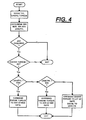
- a maximum rate of engine torque decrease (MAX) is selected which will provide the quickest shift to neutral at acceptable shift quality.
- a minimum rate of engine torque decrease (MIN) is selected which will provide a high shift quality but slowest acceptable shift.
- the drivers rate of change of throttle pedal position (rate of change of torque demand), d/dt (THL), is compared to the minimum (MIN) and maximum (MAX) reference rates. If the rate of change of throttle position exceeds the maximum reference value ((d/dt(THL))>MAX), then the engine will be commanded to decrease torque at said maximum reference rate (MAX).
- the engine will be commanded to decrease torque at said minimum reference rate (MIN). If the rate of change of throttle position is less than the maximum reference value and exceeds the minimum reference value, ((MAX)>(d/dt)(THL))>(MIN)), then the engine will be commanded to decrease torque at a rate generally equal to said rate of change of throttle position (d/dt)(THL)).
- the rate is determined by the rate of change of throttle pedal position and is subject to upper (MAX) and lower (MIN) limits.
- Fig. 1 is a schematic illustration of a vehicular drivetrain using the adaptive engine fueling control method/system of the present invention.
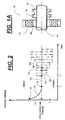
- Fig. 1A is a schematic illustration of a typical jaw clutch assembly utilized with a mechanical transmission.
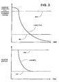
- Fig. 2 is a graphical representation of the engine fuel control of the present invention to allow disengagement of an engaged ratio.
- Fig. 3 is a graphical representation of engine torque decrease rate control according to the present invention.
- Fig.4 is a schematic illustration, in flow chart format, of the adaptive engine fuel control method/system of the present invention.
- System 10 may be fully automated, as seen by way of example in U.S. Pat. No. 4,361,060, partially automated, as seen by way of example in U.S. Pat. No's. 4,648,290, and 5,409,432, or manual with controller assist, as seen by way of example in U.S. Pat. No's. 4,850,236; 5,582,558; 5,735,771; and 6,015,366.
- a change-gear transmission 12 comprising a manually or automatically shifted main transmission section 14 connected in series with a splitter-type auxiliary transmission section 16 is drivingly connected to an internal combustion engine 18, such as a well-known gasoline or diesel engine, by a manually or automatically operated master friction clutch 20 or other non-positive coupling.
- auxiliary transmission section 16 is of the three-layer, four-speed combined splitter/range type, as illustrated in U.S. Pat. No's. 4,754,665 and 5,390,561, the disclosures of which are incorporated herein by reference.
- Engine 18 includes a crankshaft 22, which is attached to a driving member 24 of master clutch 20, which is normally frictionally engaged with a driven member 26, which is attached to the input shaft 28 of the transmission.
- a transmission output shaft 30 extends from the auxiliary transmission section 16 for driving connection to the vehicular drive wheels, as through a drive axle or the like.
- Transmissions 12, by way of example, may be of the type well known in the prior art and are sold by the assignee of this application, EATON CORPORATION, under the trademark "Super-10" and may be seen in greater detail by reference to U.S. Pat. No's. 6,015,366; 5,974,906; and 5,974,354, the disclosures of which are incorporated herein by reference.
- Controller-assisted transmission system 10 further includes rotational speed sensors 32 for sensing engine rotational speed (ES), 34 for sensing input shaft rotational speed (IS), and 36 for sensing output shaft rotational speed (OS), and providing signals indicative thereof.
- a sensor 37 provides a signal THL indicative of throttle pedal position. The signal is usually a percentage (0% to 100%) of fuel throttle position.
- Engine 18 may be electronically controlled, including an electronic controller 38 communicating over an electronic data link (DL) operating under an industry standard protocol such as SAE J-1922, SAE J-1939, ISO 11898 or the like.
- a manual clutch pedal (not shown) or an automated actuator (not shown) may be utilized to selectively engage and disengage normally engaged master clutch 20, as is well known in the prior art.
- An auxiliary section actuator 40 is provided to control shifting of the auxiliary section splitter and/or range ratios.
- the splitter actuator will be a three-position actuator, allowing the splitter section to be shifted to and maintained in a high splitter ratio, a low splitter ratio or a splitter-neutral position, the structure and advantages of which may be appreciated in greater detail by reference to U.S. Pat. No's. 5,651,292; 5,974,906; and 5,970,810, the disclosures of which are incorporated herein by reference.
- Transmission system 10 as illustrated includes a manually operated shift lever 42 having a shift knob 44 thereon.
- Shift knob 44 may be of the type described in aforementioned U.S. Pat. No. 5,957,001.
- shift lever 42 is manually manipulated in a known shift pattern for selective engagement and disengagement of various shift ratios.
- an X-Y shift actuator which by way of example may be of the types illustrated in U.S. Pat. No's. 5,481,170; 5,281,902; 4,899,609; and 4,821,590, may be provided for automated or shift-by-wire shifting the transmission main section.
- Shift Knob 44 may include an intent to shift switch 44A by which the vehicle operator will request automatic engine fueling control to relieve torque lock and allow a shift to transmission neutral.
- System 10 includes a control unit, preferably a microprocessor-based control unit of the type illustrated in U.S. Pat. No's. 4,595,986; 4,361,065; and 5,335,566, the disclosures of which are incorporated herein by reference, for receiving input signals 54 and processing same according to predetermined logic rules to issue command output signals 56 to system actuators, such as engine controller 38, auxiliary section shift actuator 40, and the like.
- a control unit preferably a microprocessor-based control unit of the type illustrated in U.S. Pat. No's. 4,595,986; 4,361,065; and 5,335,566, the disclosures of which are incorporated herein by reference, for receiving input signals 54 and processing same according to predetermined logic rules to issue command output signals 56 to system actuators, such as engine controller 38, auxiliary section shift actuator 40, and the like.
- FIG. 1A illustrates a typical jaw clutch assembly 70 for selectively engaging and disengaging a gear 72 to a shaft 74, such as a transmission main shaft, for engaging and disengaging a transmission ratio.
- clutch member 76 is splined to shaft 74 for axial movement relative thereto and rotation therewith.
- Clutch member 76 carries external clutch teeth 78 for engaging internal clutch teeth 80 formed in the inner diameter bore of gear 72.
- the clutch member 76 is axially positioned by a shift fork (not shown) or the like.
- the shift fork is typically axially positioned by a shift rail, a shift shaft, a ball ramp or ball screw, a piston, or functionally similar device.
- torque lock can be relieved by fueling the engine to cause assumed zero driveline torque and/or by forcing torque reversals which will positively cause crossings of zero driveline torque. While controlling engine fueling to aim and remain at a zero driveline torque value will result in a higher quality shift, this method may not result in actually allowing engaged jaw clutches underload to be disengaged. Using a "torque bump" or other routine to forced torque reversals across the jaw clutch to be disengaged is highly reliable, but may result in a relatively lower quality shift.
- Engine torque refers to a value indicative of an engine torque, usually gross engine torque, from which an output or flywheel torque may be calculated or estimated.
- gross engine torque is discussed in U.S. Pat. No's. 5,509,867 and 5,490,063, the disclosures of which are incorporated herein by reference.
- One or more engine torques or torque limit value may be commanded on, or read from, an industry standard data link, DL, such as an SAE J-1922, SAE J-1939 or ISO11898 compliant data link.
- DL industry standard data link
- the engine upon sensing that a shift from an engaged ratio to neutral, without disengaging the master clutch 20, is required, the engine is first commanded to ramp to a value of engine torque determined or calculated, based upon sensed system operating parameters, to correspond to zero driveline torque.
- the engine torque will be commanded to ramp down 112 to the calculated value 114 assumed to correspond to the zero driveline torque condition.
- the engine torque will be commanded to ramp up to the calculated value 114.
- the slope of the ramp 112 i.e., the rate of change of engine torque
- the engine will be commanded to remain at this condition 122 for a period of T time (T 2 -T 1 ).
- the period of time (T 2 -T 1 ) is typically about 150-300 milliseconds.
- the sensed velocity of a shift member such as for example, a shift lever 42 or shift finger SF, is compared to a reference value REF. If the shift member velocity equals or exceeds the reference value ((d/dt(SL Y-Y ))>REF), this indicates that the shift member is moving at a rate towards jaw clutch disengagement indicative of non-torque lock conditions and a torque bump routine is not necessary or desirable. In such conditions, the engine will be commanded to continue generating an output torque assumed to correspond to zero driveline torque (solid line 126) until transmission neutral is sensed.
- torque lock conditions may exist and a torque bump fueling routine of the engine (dashed lines 128) to forced torque reversals (130) at the jaw clutch will commence until neutral is sensed and/or a time period expires.
- the magnitude and/or shape of the torque bumps 128 may vary with time.
- Automated transmissions attempt to gently and gradually ramp down engine torque (i.e., fueling) to provide a smooth disengagement which is perceived as a "high quality shift".
- a problem with this technique is that the time required to perform the step of ramping down fuel/torque may result in a shift that takes too long to complete. If the shift takes too long to complete, the vehicle will slow down more than desired. Also, engine speed at shift completion will be lower than at shift initiation. If torque is ramped down excessively quickly, then shift quality may be lower than desired.
- a method/system for controlling engine torque ramp down rate which will vary the rate depending on driver demand and minimum and maximum allowable rates.
- a maximum rate of engine torque decrease (MAX) is selected which will provide the quickest shift to neutral at acceptable shift quality.
- a minimum rate of engine torque decrease (MIN) is selected which will provide a high shift quality but slowest acceptable shift.
- the drivers rate of change of throttle pedal position (rate of change of torque demand), d/dt (THL), is compared to the minimum (MIN) and maximum (MAX) reference rates. If the rate of change of throttle position exceeds the maximum reference value ((d/dt(THL))>MAX), then the engine will be commanded to decrease torque at said maximum reference rate (MAX).
- Fig. 3 is schematic illustration, in graphical format, of the control system/method of the present invention.
- Fig. 4 is a schematic illustration, in flow chart format, of the adaptive engine fueling control subroutine of the present invention. Preferably, the subroutine will be performed during each control loop.
- the maximum ramp rate i.e., MAX rate of change of engine torque
Landscapes
- Engineering & Computer Science (AREA)
- Chemical & Material Sciences (AREA)
- Combustion & Propulsion (AREA)
- Mechanical Engineering (AREA)
- Transportation (AREA)
- General Engineering & Computer Science (AREA)
- Automation & Control Theory (AREA)
- Control Of Vehicle Engines Or Engines For Specific Uses (AREA)
- Control Of Transmission Device (AREA)
- Control Of Driving Devices And Active Controlling Of Vehicle (AREA)
- Electrical Control Of Air Or Fuel Supplied To Internal-Combustion Engine (AREA)
Applications Claiming Priority (2)
| Application Number | Priority Date | Filing Date | Title |
|---|---|---|---|
| US09/742,244 US6406403B1 (en) | 2000-12-21 | 2000-12-21 | Torque ramp down control |
| US742244 | 2000-12-21 |
Publications (2)
| Publication Number | Publication Date |
|---|---|
| EP1216877A2 true EP1216877A2 (de) | 2002-06-26 |
| EP1216877A3 EP1216877A3 (de) | 2005-07-27 |
Family
ID=24984041
Family Applications (1)
| Application Number | Title | Priority Date | Filing Date |
|---|---|---|---|
| EP01130072A Withdrawn EP1216877A3 (de) | 2000-12-21 | 2001-12-18 | Brennkraftmaschinensteuerung zur Erzeugung eines abnehmenden Antriebsmoments |
Country Status (4)
| Country | Link |
|---|---|
| US (1) | US6406403B1 (de) |
| EP (1) | EP1216877A3 (de) |
| JP (1) | JP2002235573A (de) |
| BR (1) | BR0106443A (de) |
Cited By (1)
| Publication number | Priority date | Publication date | Assignee | Title |
|---|---|---|---|---|
| WO2013156310A1 (de) * | 2012-04-18 | 2013-10-24 | Voith Patent Gmbh | Verfahren zum aufbau oder abbau von drehmoment |
Families Citing this family (7)
| Publication number | Priority date | Publication date | Assignee | Title |
|---|---|---|---|---|
| JP3709787B2 (ja) * | 2000-12-20 | 2005-10-26 | 日産自動車株式会社 | 変速時トルクダウン制御装置 |
| US7131933B2 (en) * | 2001-12-07 | 2006-11-07 | Toyota Jidosha Kabushiki Kaisha | Vehicle control apparatus having means for changing inertia torque of engine during shifting action or during switching of operating state of lock-up clutch |
| JP2004068686A (ja) * | 2002-08-05 | 2004-03-04 | Jatco Ltd | エンジントルク制御装置 |
| US8448731B2 (en) * | 2007-11-05 | 2013-05-28 | GM Global Technology Operations LLC | Method and apparatus for determination of fast actuating engine torque for a hybrid powertrain system |
| JP5203105B2 (ja) * | 2008-09-05 | 2013-06-05 | ヤマハ発動機株式会社 | 変速制御システムおよび車両 |
| DE102009046863A1 (de) * | 2009-11-19 | 2011-05-26 | Zf Friedrichshafen Ag | Verfahren zum Betätigen einer Kupplung |
| EP2692523A4 (de) * | 2011-03-31 | 2015-05-06 | Mitsubishi Plastics Inc | Gasbarrierenlaminatfilm und herstellungsverfahren dafür |
Citations (10)
| Publication number | Priority date | Publication date | Assignee | Title |
|---|---|---|---|---|
| US4593580A (en) | 1980-12-05 | 1986-06-10 | Volkswagenwerk Aktiengesellschaft | Device for shifting without clutch and without synchronizing elements in a multiple gear ratio transmission of a vehicle |
| US4850236A (en) | 1987-11-20 | 1989-07-25 | Eaton Corporation | Vehicle drive line shift control system and method |
| US4937749A (en) | 1987-12-10 | 1990-06-26 | Eaton Corporation | Semi-automatic mechanical transmission control and control method |
| US5272939A (en) | 1992-07-06 | 1993-12-28 | Eaton Corporation | Shift enable control method/system |
| US5335566A (en) | 1992-07-06 | 1994-08-09 | Eaton Corporation | Shift control method/system |
| US5582558A (en) | 1995-07-27 | 1996-12-10 | Rockwell International Corporation | Combined system for assisting shifting of manual transmission |
| US5735771A (en) | 1996-04-30 | 1998-04-07 | Eaton Corporation | Semi-automatic shift implementation |
| US5775639A (en) | 1994-12-15 | 1998-07-07 | Fage; Etienne | Thrust reverser with pivoting doors which can move in translation |
| US6015366A (en) | 1996-04-30 | 2000-01-18 | Eaton Corporation | Vehicular semi-automatic shift implementation system for lever-shifted, splitter-type, compound transmission with an intent-to-shift switch operable to cause automatic control of engine fueling and initiation of a splitter shift |
| US6126570A (en) | 1999-07-06 | 2000-10-03 | Zf Meritor | Shift synchronization using decaying torque |
Family Cites Families (9)
| Publication number | Priority date | Publication date | Assignee | Title |
|---|---|---|---|---|
| US5533946A (en) * | 1994-04-08 | 1996-07-09 | Eaton Corporation | Engine deceleration determination method/system for updating a control parameter |
| US5582069A (en) * | 1994-05-16 | 1996-12-10 | Eaton Corporation | Engine accessory torque and engine deceleration rate determination method/system |
| US5517411A (en) * | 1995-02-13 | 1996-05-14 | Eaton Corporation | Neutral attainment control system/method for controlling shifting in vehicular automated mechanical transmission systems |
| US5679093A (en) * | 1995-07-27 | 1997-10-21 | Rockwell International Corporation | Engine speed retardation on transmission upshift |
| US5743143A (en) | 1996-08-09 | 1998-04-28 | Eaton Corporation | Transmission shifting mechanism and position sensor |
| JPH10243502A (ja) * | 1997-02-26 | 1998-09-11 | Aisin Aw Co Ltd | 車両用駆動装置の制御装置 |
| US5950491A (en) | 1998-04-01 | 1999-09-14 | Eaton Corporation | Adaptive neutral sensing |
| US5911787A (en) | 1998-04-01 | 1999-06-15 | Eaton Corporation | Dynamic range shift actuation |
| US6352492B1 (en) * | 2000-04-06 | 2002-03-05 | Eaton Corporation | Torque modulation shift control system and method |
-
2000
- 2000-12-21 US US09/742,244 patent/US6406403B1/en not_active Expired - Fee Related
-
2001
- 2001-12-18 EP EP01130072A patent/EP1216877A3/de not_active Withdrawn
- 2001-12-20 BR BR0106443-6A patent/BR0106443A/pt not_active IP Right Cessation
- 2001-12-20 JP JP2001387838A patent/JP2002235573A/ja not_active Withdrawn
Patent Citations (11)
| Publication number | Priority date | Publication date | Assignee | Title |
|---|---|---|---|---|
| US4593580A (en) | 1980-12-05 | 1986-06-10 | Volkswagenwerk Aktiengesellschaft | Device for shifting without clutch and without synchronizing elements in a multiple gear ratio transmission of a vehicle |
| US4850236A (en) | 1987-11-20 | 1989-07-25 | Eaton Corporation | Vehicle drive line shift control system and method |
| US4937749A (en) | 1987-12-10 | 1990-06-26 | Eaton Corporation | Semi-automatic mechanical transmission control and control method |
| US5272939A (en) | 1992-07-06 | 1993-12-28 | Eaton Corporation | Shift enable control method/system |
| US5335566A (en) | 1992-07-06 | 1994-08-09 | Eaton Corporation | Shift control method/system |
| US5272939B1 (en) | 1992-07-06 | 1994-12-06 | Eaton Corp | Shift enable control method/system |
| US5775639A (en) | 1994-12-15 | 1998-07-07 | Fage; Etienne | Thrust reverser with pivoting doors which can move in translation |
| US5582558A (en) | 1995-07-27 | 1996-12-10 | Rockwell International Corporation | Combined system for assisting shifting of manual transmission |
| US5735771A (en) | 1996-04-30 | 1998-04-07 | Eaton Corporation | Semi-automatic shift implementation |
| US6015366A (en) | 1996-04-30 | 2000-01-18 | Eaton Corporation | Vehicular semi-automatic shift implementation system for lever-shifted, splitter-type, compound transmission with an intent-to-shift switch operable to cause automatic control of engine fueling and initiation of a splitter shift |
| US6126570A (en) | 1999-07-06 | 2000-10-03 | Zf Meritor | Shift synchronization using decaying torque |
Cited By (1)
| Publication number | Priority date | Publication date | Assignee | Title |
|---|---|---|---|---|
| WO2013156310A1 (de) * | 2012-04-18 | 2013-10-24 | Voith Patent Gmbh | Verfahren zum aufbau oder abbau von drehmoment |
Also Published As
| Publication number | Publication date |
|---|---|
| EP1216877A3 (de) | 2005-07-27 |
| JP2002235573A (ja) | 2002-08-23 |
| US6406403B1 (en) | 2002-06-18 |
| US20020082137A1 (en) | 2002-06-27 |
| BR0106443A (pt) | 2002-08-20 |
Similar Documents
| Publication | Publication Date | Title |
|---|---|---|
| US5634867A (en) | Main clutch reengagement control for a double clutch downshift | |
| US7344474B2 (en) | Control for selecting automated transmission system shift strategy | |
| US5894758A (en) | Assisted lever-shifted transmission | |
| US6042507A (en) | Torque converter lockup control | |
| US6149545A (en) | Automated transmission upshift control | |
| US6066071A (en) | Automated transmission downshift control | |
| US6113516A (en) | Adaptive automated transmission upshift control | |
| US6520889B1 (en) | Adaptive engine control for shifting to neutral | |
| EP1152172B1 (de) | Steuerung des Hochschaltvorganges eines automatisierten Getriebes | |
| US6406403B1 (en) | Torque ramp down control | |
| US6220219B1 (en) | Engine speed control for decreasing engine speed | |
| US6327529B1 (en) | Range control | |
| EP1070880B1 (de) | Adaptive Rückschaltungssteuerung für automatisiertes Getriebe | |
| EP1514041B1 (de) | Verfahren zur erfassung eines fehl-leerlaufzustands in einem automatikgetriebesystem | |
| EP1606529B1 (de) | Einkuppelnsteuerungssystem und -verfahren für eine kupplung | |
| US6461272B1 (en) | Vehicle synchronization algorithm for driveline protection | |
| US6491603B1 (en) | Automated transmission shift control | |
| US6283892B1 (en) | Active in-gear positioning |
Legal Events
| Date | Code | Title | Description |
|---|---|---|---|
| PUAI | Public reference made under article 153(3) epc to a published international application that has entered the european phase |
Free format text: ORIGINAL CODE: 0009012 |
|
| AK | Designated contracting states |
Kind code of ref document: A2 Designated state(s): AT BE CH CY DE DK ES FI FR GB GR IE IT LI LU MC NL PT SE TR |
|
| AX | Request for extension of the european patent |
Free format text: AL;LT;LV;MK;RO;SI |
|
| PUAL | Search report despatched |
Free format text: ORIGINAL CODE: 0009013 |
|
| AK | Designated contracting states |
Kind code of ref document: A3 Designated state(s): AT BE CH CY DE DK ES FI FR GB GR IE IT LI LU MC NL PT SE TR |
|
| AX | Request for extension of the european patent |
Extension state: AL LT LV MK RO SI |
|
| RIC1 | Information provided on ipc code assigned before grant |
Ipc: 7F 02D 41/14 B Ipc: 7F 16H 61/04 B Ipc: 7F 02D 41/16 B Ipc: 7B 60K 41/10 A |
|
| AKX | Designation fees paid | ||
| STAA | Information on the status of an ep patent application or granted ep patent |
Free format text: STATUS: THE APPLICATION IS DEEMED TO BE WITHDRAWN |
|
| 18D | Application deemed to be withdrawn |
Effective date: 20060128 |
|
| REG | Reference to a national code |
Ref country code: DE Ref legal event code: 8566 |