EP1216893A2 - Fahrzeuglenkrad - Google Patents
Fahrzeuglenkrad Download PDFInfo
- Publication number
- EP1216893A2 EP1216893A2 EP01129261A EP01129261A EP1216893A2 EP 1216893 A2 EP1216893 A2 EP 1216893A2 EP 01129261 A EP01129261 A EP 01129261A EP 01129261 A EP01129261 A EP 01129261A EP 1216893 A2 EP1216893 A2 EP 1216893A2
- Authority
- EP
- European Patent Office
- Prior art keywords
- skeleton
- steering wheel
- vehicle steering
- gas bag
- wheel according
- Prior art date
- Legal status (The legal status is an assumption and is not a legal conclusion. Google has not performed a legal analysis and makes no representation as to the accuracy of the status listed.)
- Granted
Links
- 238000002347 injection Methods 0.000 claims abstract 2
- 239000007924 injection Substances 0.000 claims abstract 2
- 238000007664 blowing Methods 0.000 description 3
- 239000002184 metal Substances 0.000 description 2
- 238000006073 displacement reaction Methods 0.000 description 1
- 230000013011 mating Effects 0.000 description 1
- 230000001960 triggered effect Effects 0.000 description 1
Images

Classifications
-
- B—PERFORMING OPERATIONS; TRANSPORTING
- B60—VEHICLES IN GENERAL
- B60R—VEHICLES, VEHICLE FITTINGS, OR VEHICLE PARTS, NOT OTHERWISE PROVIDED FOR
- B60R21/00—Arrangements or fittings on vehicles for protecting or preventing injuries to occupants or pedestrians in case of accidents or other traffic risks
- B60R21/02—Occupant safety arrangements or fittings, e.g. crash pads
- B60R21/16—Inflatable occupant restraints or confinements designed to inflate upon impact or impending impact, e.g. air bags
- B60R21/20—Arrangements for storing inflatable members in their non-use or deflated condition; Arrangement or mounting of air bag modules or components
- B60R21/203—Arrangements for storing inflatable members in their non-use or deflated condition; Arrangement or mounting of air bag modules or components in steering wheels or steering columns
- B60R21/2035—Arrangements for storing inflatable members in their non-use or deflated condition; Arrangement or mounting of air bag modules or components in steering wheels or steering columns using modules containing inflator, bag and cover attachable to the steering wheel as a complete sub-unit
- B60R21/2037—Arrangements for storing inflatable members in their non-use or deflated condition; Arrangement or mounting of air bag modules or components in steering wheels or steering columns using modules containing inflator, bag and cover attachable to the steering wheel as a complete sub-unit the module or a major component thereof being yieldably mounted, e.g. for actuating the horn switch or for protecting the driver in a non-deployment situation
-
- B—PERFORMING OPERATIONS; TRANSPORTING
- B60—VEHICLES IN GENERAL
- B60Q—ARRANGEMENT OF SIGNALLING OR LIGHTING DEVICES, THE MOUNTING OR SUPPORTING THEREOF OR CIRCUITS THEREFOR, FOR VEHICLES IN GENERAL
- B60Q5/00—Arrangement or adaptation of acoustic signal devices
- B60Q5/001—Switches therefor
- B60Q5/003—Switches therefor mounted on the steering wheel
-
- B—PERFORMING OPERATIONS; TRANSPORTING
- B62—LAND VEHICLES FOR TRAVELLING OTHERWISE THAN ON RAILS
- B62D—MOTOR VEHICLES; TRAILERS
- B62D1/00—Steering controls, i.e. means for initiating a change of direction of the vehicle
- B62D1/02—Steering controls, i.e. means for initiating a change of direction of the vehicle vehicle-mounted
- B62D1/04—Hand wheels
Definitions
- the invention relates to a vehicle steering wheel, with a skeleton, a Airbag module, which is attached to the skeleton so that it can move axially Pressing the gas bag module closed a contact to actuate the horn and with a resilient return element for the gas bag module, wherein the airbag module is an airbag with a blowing opening defining Opening edge as well as a clamping inside on the opening edge Has flange for attaching the gas bag.
- Airbag modules that are movable on the vehicle steering wheel for horn actuation attached, are referred to as "floating horn" modules.
- the gas bag must be firmly attached to the gas bag module in the area of the opening edge when unfolding be attached so as not to be thrown off by the thrust generated by the gas released to be torn out of the module.
- the gas bag in the area of Opening edge usually clamped between two sheets, being on the Inside the opening edge, a flange usually in the form of a Metal ring is inserted. This flange is used in the prior art pressed a flange of the gas generator, so that between these two parts the gas bag is clamped.
- the gas generator is on a gas generator support plate attached, which in turn at another point on the skeleton or a part attached to the skeleton is axially displaceable.
- the single ones Parts must be designed to be stable to withstand the forces Introduce gas bags into the skeleton.
- the invention creates a vehicle steering wheel that is lighter, more stable and out fewer parts is formed than previously known.
- This will be one Vehicle steering wheel of the type mentioned achieved in that directly on Attack flange bearing pins that are on the skeleton or one immediately on Skeleton non-slidably attached part are attached.
- Vehicle steering wheel becomes the force exerted on the flange preferably initiated directly into the skeleton and not over numerous other connecting elements and parts such as the flange on the generator Generator carrier sheet and a sheet on the skeleton. Due to the direct application of force into the skeleton or one that is preferably attached directly to the skeleton Partly fewer fastening elements are provided than in the prior art, because the load-bearing intermediate plates and their fastenings can omitted.
- the mounting pins are preferably attached to the skeleton in such a way that that they have an axial movement of the gas bag module together with bearing pins Operation of the horn.
- the axial bearing is in the range of Steering wheel skeletons arranged where more space is available than in the area of the gas bag module.
- one of the at least one bearing pin can closing contacts may be attached so that the bearing pin together with the contact forms a pre-assembled unit and only a few parts when installing the Airbag module must be installed in the steering wheel.
- the positioning pins can also guide the gas bag module from the side form, so that additional guide surfaces are unnecessary.
- the bearing pins are as Set screws executed. Grip the nuts screwed on the setscrews directly on the skeleton or on the non-displaceably attached to the skeleton Part of. The nuts have a lateral guide for the gas bag module on the outside.
- the skeleton or the one on the skeleton does not have immediately slidably attached part a guide sleeve in which the nut slides.
- bearing pins with a Snap connection is fixed on the skeleton side.
- the Storage pins if they are designed as grub screws, each on threaded end screwed on a nut with a molded locking lug his.
- each bearing pin is composed of several parts, like as a grub screw with screwed nut, can be between the nut and a gas generator carrier are preferably clamped to the flange. Since the The gas generator carrier no longer has to absorb any load when the gas bag is deployed has, it can be designed as a plastic part, which increases the weight of the vehicle steering wheel will reduce.
- One embodiment sees this Connection before that the gas generator carrier as a cup-shaped housing of Airbag module is executed.
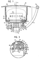
- a vehicle steering wheel which has a steering wheel skeleton 10 has, for example, die cast.
- Figure 1 is only the skeletal section shown in the area of the hub 12.
- On the right half are stylized ones Spoke 14 and the steering wheel rim 16 indicated.
- the axis A is the imaginary one Center axis of the steering shaft.
- a gas bag module 18 is movable on the skeleton 10 in the axial direction stored.
- the gas bag module has a cup-shaped plastic housing 20, too Gas generator carrier called, which to the occupant through a cover cap 22 is closed.
- the housing 20 are a folded gas bag 24, the upper one External geometry is symbolized by broken lines, one inside the Gas bag 24 protruding gas generator 26 and an annular flange 28 Arranged sheet metal.
- the gas bag has an opening, called a blowing opening 30, through which the gas generator 26 extends partially into the interior of the gas bag 24 extends.
- the so-called opening edge 32 defining the blowing opening of the gas bag lies immediately below the flange 28.
- Towards the hub 12 is below the opening edge 32 of the bottom part 36 of the housing and on the underside of which an annular flange 34 formed on the generator 26.
- bearing pins 40 Only three bearing pins 40 are distributed around the circumference of the flange 28 directly and permanently attached by reshaping the bearing pins 40.
- the Bearing pins are designed as threaded pins and extend through each have an associated opening in the opening edge 32, in the bottom part 36 of the Housing 20 and in the ring flange 34. There is one on each set screw from below Nut 44 screwed so that between the flange 28 and the nut 44 of Opening edge 32, the bottom part 36 and the ring flange 34 are clamped. In this way, the gas bag 24 is firmly locked on the vehicle steering wheel.
- the Nuts 44 have a detent 50 in the form of a conical at the free end End with an undercut 52 into which one is directly on an extension 54 of the skeleton 10 attached retaining spring 56 can snap. In this embodiment therefore only needs to mount the gas bag module from above are pressed in until the springs 56 snap into the undercuts 52.
- the force is applied via the bearing pins 40 when the gas bag 24 unfolds, it is introduced directly into the skeleton 20 without that additional intermediate plates are required.
- the housing 20 and the Ring flange 34 are low loads when unfolding the gas bag exposed.
- the gas bag module is axially displaceable through the snap connection stored, a resilient return element 60 in the form of a coil spring between the bottom of the gas bag module 18 and the top of the Skeleton 10 is clamped.
- FIG. 2 corresponds in part to that in FIG. 1, parts having the same function have the reference numerals already introduced.
- FIG. 2 there is a fastening plate 80 directly attached to the skeleton 10 and not slidable to it.
- the gas generator 26 does not have any directly on it in this embodiment attached ring flange 34. Rather, between the gas generator 26 and the ring flange 34 a rubber sleeve 82 for vibration decoupling of the gas generator 26 is provided.
- the gas bag module 18 is also axially displaceable mounted on skeleton 10, more precisely on part 80.
- Several positioning pins 40 are as set screws formed, which are permanently fixed in the flange 28.
- the bearing pins 40 extend through openings in the gas bag 24, the underlying ring flange 34 and a bottom 36.
- the bottom of the bearing pins 40th screwed nuts 44 have a protruding head 86 which acts as an axial Stop serves, and a socket-like section with a circular cylindrical Outer surface, which acts as a lateral guide 88 of the gas bag module 18.
- One in Part 80 attached guide sleeve 90 receives the nut 44.
- the gas bag module 18 is not only axial, but also led sideways.
- the bearing pins 40 have a resilient one Contact 90 attached, which is held in an elastic receptacle 92.
- On the guide sleeve 90 is a mating contact with a base part 94 and a spring 96 attached. If the contacts 90, 96 by moving the gas bag module 18 touch each other in the direction of the arrow, the horn signal is triggered.
- the special feature of both shown embodiments is that only the storage pins 40 individual parts within the gas bag module 18 (gas generator with ring flange 34, gas bag 24, flange 28 and gas generator support 20) are attached and the entirety of the gas bag module 18 on the Storage pins 40 is also axially displaceably attached to the skeleton side.
- the nut 44 serving as a guide can of course also be used for the Embodiment according to Figure 1 can be used.
- a corresponding embodiment would correspond to that shown in Figure 3 when the part 80 the skeleton would form.
Landscapes
- Engineering & Computer Science (AREA)
- Mechanical Engineering (AREA)
- Chemical & Material Sciences (AREA)
- Combustion & Propulsion (AREA)
- Transportation (AREA)
- Physics & Mathematics (AREA)
- Acoustics & Sound (AREA)
- Air Bags (AREA)
- Steering Controls (AREA)
Abstract
Description
Claims (11)
- Fahrzeuglenkrad, mit
einem Skelett (10),
einem Gassackmodul (18), das am Skelett (10) so axial beweglich angebracht ist, daß durch Andrücken des Gassackmoduls (18) ein Kontakt (70, 90, 96) zur Betätigung des Hupensignals geschlossen wird,
mit einem nachgiebigem Rückstellelement (60) für das Gassackmodul (18),
wobei das Gassackmodul (18) einen Gassack (24) mit einem eine Einblasöffnung (30) definierenden Öffnungsrand (32) sowie einen innenseitig den Öffnungsrand (32) klemmenden Flansch (28) zur Befestigung des Gassacks (24) aufweist,
dadurch gekennzeichnet, daß
unmittelbar am Flansch (28) Lagerungsstifte (40) angreifen, die am Skelett (10) oder einem unmittelbar am Skelett (10) nicht verschiebbar angebrachten Teil (80) befestigt sind. - Fahrzeuglenkrad nach Anspruch 1, dadurch gekennzeichnet, daß die Befestigung der Lagerungsstifte (40) am Skelett (10) so ausgeführt sind, daß sie eine Axialbewegung des Gassackmoduls (18) samt Lagerungsstifte (40) zur Betätigung des Hupensignals zuläßt.
- Fahrzeuglenkrad nach einem der vorhergehenden Ansprüche, dadurch gekennzeichnet, daß an wenigstens einem Lagerungsstift (40) einer der zu schließenden Kontakte (90) angebracht ist.
- Fahrzeuglenkrad nach einem der vorhergehenden Ansprüche, dadurch gekennzeichnet, daß die Lagerungsstifte (40) auch die seitliche Führung des Gassackmoduls (18) bilden.
- Fahrzeuglenkrad nach einem der vorhergehenden Ansprüche, dadurch gekennzeichnet, daß die Lagerungsstifte (40) als Gewindestifte ausgeführt sind und daß am Skelett (10) oder an dem am Skelett (10) unmittelbar und nicht verschiebbar angebrachten Teil (80) angreifende Muttern (44), in die die Lagerungsstifte (40) eingedreht sind, außenseitig eine seitliche Führung (88) für das Gassackmodul (18) bilden.
- Fahrzeuglenkrad nach Anspruch 5, dadurch gekennzeichnet, daß am Skelett (10) oder dem am Skelett unmittelbar nicht verschiebbar angebrachten Teil (80) für jede Mutter (44) eine Führungshülse (90) vorgesehen ist.
- Fahrzeuglenkrad nach einem der Ansprüche 1 bis 4, dadurch gekennzeichnet, daß die Lagerungsstifte (40) mit einer Rastverbindung skelettseitig befestigt sind.
- Fahrzeuglenkrad nach Anspruch 7, dadurch gekennzeichnet, daß die Lagerungsstifte (40) als Gewindestifte ausgeführt sind, auf denen am gewindeseitigen Ende eine Mutter (44) mit einer angeformten Rastnase (50) aufgeschraubt sind.
- Fahrzeuglenkrad nach einem der Ansprüche 5, 6 und 8, dadurch gekennzeichnet, daß zwischen der Mutter (44) und dem Flansch (28) ein Gasgeneratorträger (20) geklemmt ist.
- Fahrzeuglenkrad nach einem der vorhergehenden Ansprüche, dadurch gekennzeichnet, daß ein Gasgeneratorträger (20) aus Kunststoff vorgesehen ist.
- Fahrzeuglenkrad nach einem der vorhergehenden Ansprüche, dadurch gekennzeichnet, daß ein als topfförmiges Gehäuse des Gassackmoduls (18) ausgebildeter Gasgeneratorträger (20) vorgesehen ist.
Applications Claiming Priority (2)
| Application Number | Priority Date | Filing Date | Title |
|---|---|---|---|
| DE20021532U DE20021532U1 (de) | 2000-12-20 | 2000-12-20 | Fahrzeuglenkrad |
| DE20021532U | 2000-12-20 |
Publications (3)
| Publication Number | Publication Date |
|---|---|
| EP1216893A2 true EP1216893A2 (de) | 2002-06-26 |
| EP1216893A3 EP1216893A3 (de) | 2002-10-09 |
| EP1216893B1 EP1216893B1 (de) | 2005-03-09 |
Family
ID=7950312
Family Applications (1)
| Application Number | Title | Priority Date | Filing Date |
|---|---|---|---|
| EP01129261A Expired - Lifetime EP1216893B1 (de) | 2000-12-20 | 2001-12-12 | Fahrzeuglenkrad |
Country Status (4)
| Country | Link |
|---|---|
| US (2) | US6682092B2 (de) |
| EP (1) | EP1216893B1 (de) |
| DE (2) | DE20021532U1 (de) |
| ES (1) | ES2238377T3 (de) |
Families Citing this family (35)
| Publication number | Priority date | Publication date | Assignee | Title |
|---|---|---|---|---|
| DE10146175A1 (de) * | 2001-09-19 | 2003-04-17 | Daimler Chrysler Ag | Lenkradeinheit für ein Kraftfahrzeug |
| DE20117140U1 (de) | 2001-10-23 | 2002-03-28 | TRW Automotive Safety Systems GmbH & Co. KG, 63743 Aschaffenburg | Baugruppe mit Gassack-Modul |
| US6830263B2 (en) * | 2002-02-08 | 2004-12-14 | Key Safety Systems, Inc. | Method for attaching an airbag module |
| US20040012177A1 (en) * | 2002-05-16 | 2004-01-22 | Takata-Petri Ag | Airbag module with elastic mounting of the gas generator |
| DE20210741U1 (de) * | 2002-07-16 | 2002-11-28 | TRW Automotive Safety Systems GmbH & Co. KG, 63743 Aschaffenburg | Fahrzeug-Lenkrad |
| EP1393991B1 (de) * | 2002-08-27 | 2006-05-24 | TRW Automotive Safety Systems GmbH | Gassackmodul |
| DE20303303U1 (de) * | 2003-02-28 | 2003-07-03 | TRW Automotive Safety Systems GmbH, 63743 Aschaffenburg | Gassackmodul |
| US7059631B2 (en) * | 2003-04-29 | 2006-06-13 | Toyoda Gosei Co., Ltd. | Method and apparatus for coupling a driver's side airbag to a steering wheel |
| DE20307142U1 (de) * | 2003-05-07 | 2003-09-18 | TRW Automotive Safety Systems GmbH, 63743 Aschaffenburg | Baugruppe |
| US7159897B2 (en) * | 2003-07-21 | 2007-01-09 | Delphi Technologies, Inc. | Isolated ground for horn mechanism |
| KR100519231B1 (ko) * | 2003-08-14 | 2005-10-06 | 현대모비스 주식회사 | 차량의 혼 스위치 어셈블리 |
| US7055854B2 (en) * | 2004-03-03 | 2006-06-06 | Autoliv Asp, Inc. | Snap-in castanet airbag module for a vehicular steering wheel |
| US7556281B2 (en) * | 2004-03-16 | 2009-07-07 | Toyoda Gosei Co., Ltd. | Stamped airbag retention members and method of airbag assembly |
| DE102004015529B4 (de) * | 2004-03-30 | 2009-08-27 | Key Safety Systems, Inc., Sterling Heights | Lenkrad für ein Fahrzeug |
| EP1595754B1 (de) * | 2004-05-10 | 2008-06-04 | Key Safety Systems, Inc. | Baugruppe mit einem Lenkrad und einem Gassackmodul |
| DE102004037462A1 (de) * | 2004-08-03 | 2006-03-16 | Trw Automotive Safety Systems Gmbh & Co. Kg | Baugruppe mit Lenkrad und Gassackmodul |
| DE202004018362U1 (de) * | 2004-11-26 | 2006-04-06 | Trw Automotive Safety Systems Gmbh & Co. Kg | Fahrzeuglenkrad mit Airbagmodul |
| JP4797584B2 (ja) * | 2005-03-16 | 2011-10-19 | タカタ株式会社 | エアバッグ装置付きステアリングホイール |
| US7380817B2 (en) * | 2005-03-29 | 2008-06-03 | Key Safety Systems, Inc. | Assembly for retaining an airbag module to a steering wheel |
| US7374199B2 (en) * | 2005-04-04 | 2008-05-20 | Arc Automotive, Inc. | Air bag inflator vibration damper |
| DE202005019960U1 (de) * | 2005-12-21 | 2006-04-13 | Trw Automotive Safety Systems Gmbh | Gassackmodul |
| DE202005020078U1 (de) * | 2005-12-21 | 2006-02-16 | Trw Automotive Safety Systems Gmbh | Gassackmodul |
| DE202006014054U1 (de) | 2006-09-13 | 2006-12-21 | Trw Automotive Safety Systems Gmbh | Fahrzeuglenkrad |
| DE102007037604A1 (de) | 2007-08-07 | 2009-02-12 | Takata-Petri Ag | Airbagmodul für ein Kraftfahrzeug |
| JP5104155B2 (ja) * | 2007-09-20 | 2012-12-19 | 豊田合成株式会社 | エアバッグ装置付きステアリングホイール |
| DE102009013802B4 (de) * | 2009-03-18 | 2017-03-16 | Trw Automotive Safety Systems Gmbh | Gassackmodul |
| JP5746702B2 (ja) * | 2010-09-09 | 2015-07-08 | 本田技研工業株式会社 | エアバッグモジュールを備えたステアリングホイール構造 |
| JP2014196071A (ja) * | 2013-03-29 | 2014-10-16 | 日本プラスト株式会社 | エアバッグ装置 |
| JP6744579B2 (ja) * | 2016-07-29 | 2020-08-19 | 豊田合成株式会社 | エアバッグ装置の支持構造 |
| US11718257B2 (en) * | 2016-12-15 | 2023-08-08 | Zf Passive Safety Systems Us Inc | Coupling device for mounting an airbag module to be oscillating on a vehicle steering wheel |
| DE102016124530A1 (de) * | 2016-12-15 | 2018-06-21 | Trw Automotive Safety Systems Gmbh | Kopplungsvorrichtung zur schwingfähigen Befestigung eines Gassackmoduls an einem Fahrzeuglenkrad |
| EP3499076B1 (de) * | 2017-12-15 | 2021-03-31 | Vibracoustic Forsheda AB | Dämpfereinheit, dämpferbaugruppe und verfahren zur herstellung einer dämpfereinheit |
| JP6885366B2 (ja) * | 2018-03-29 | 2021-06-16 | 豊田合成株式会社 | エアバッグ装置 |
| JP7347149B2 (ja) * | 2019-11-18 | 2023-09-20 | Joyson Safety Systems Japan合同会社 | ステアリングホイール |
| KR20240033489A (ko) * | 2022-09-05 | 2024-03-12 | 현대자동차주식회사 | 스티어링휠과, 그 스티어링휠의 댐퍼유닛 |
Family Cites Families (19)
| Publication number | Priority date | Publication date | Assignee | Title |
|---|---|---|---|---|
| US4785144A (en) * | 1988-02-16 | 1988-11-15 | General Motors Corporation | Horn blowing switch arrangement |
| US5410114A (en) * | 1992-12-25 | 1995-04-25 | Toyoda Gosei Co., Ltd. | Steering wheel horn switch mechanism |
| US5350190A (en) * | 1993-07-06 | 1994-09-27 | Primrose, Inc. | Air bag assembly mount including snap-fit horn attachment |
| US5380037A (en) * | 1993-10-25 | 1995-01-10 | General Motors Corporation | Snap-in inflatable restraint module mounting mechanism including latch elements |
| US5409256A (en) * | 1994-01-04 | 1995-04-25 | General Motors Corporation | Driver-side air bag module assembly |
| US5560642A (en) * | 1995-01-06 | 1996-10-01 | Takata, Inc. | Driver air bag module assembly |
| DE19503816B4 (de) * | 1995-02-06 | 2007-03-22 | Volkswagen Ag | Anordnung zur Befestigung eines aus einem Gehäuseboden und einem Gehäusedeckel bestehenden Gehäuses im Lenkrad |
| EP0739786B2 (de) | 1995-04-27 | 2003-05-21 | Toyoda Gosei Co., Ltd. | Lenkrad mit einbegriffener Luftsackeinheit |
| US5636858A (en) * | 1995-05-05 | 1997-06-10 | General Motors Corporation | Air bag module |
| JPH0958393A (ja) | 1995-08-24 | 1997-03-04 | Bridgestone Corp | エアバッグ装置 |
| US5678848A (en) * | 1996-01-17 | 1997-10-21 | Morton International, Inc. | Air bag module with combined assembly and mounting hardware |
| DE69725246T2 (de) * | 1996-08-06 | 2004-07-29 | Toyoda Gosei Co., Ltd., Haruhi | Lenkrad |
| DE29616916U1 (de) * | 1996-09-27 | 1997-01-30 | Trw Occupant Restraint Systems Gmbh, 73551 Alfdorf | Gassack-Modul für ein Fahrzeuginsassen-Rückhaltesystem |
| US5762359A (en) * | 1996-10-02 | 1998-06-09 | General Motors Corporation | Air bag module and steering wheel assembly |
| DE19724029A1 (de) * | 1997-06-06 | 1998-12-24 | Takata Europ Gmbh | Airbag-Vorrichtung |
| FR2769881B1 (fr) * | 1997-10-21 | 2000-01-28 | Ecia Equip Composants Ind Auto | Systeme de fixation d'un module a sac gonflable sur une piece d'armature notamment d'un volant de direction de vehicule automobile |
| DE19858691B4 (de) * | 1998-12-18 | 2010-01-07 | Delphi Automotive Systems Deutschland Gmbh | Luftsackmodul für Kraftfahrzeuge |
| DE29906374U1 (de) * | 1999-04-09 | 1999-06-24 | TRW Automotive Safety Systems GmbH & Co.KG, 63743 Aschaffenburg | Lenkrad mit Airbagmodul und Hupkontakt |
| JP2001138851A (ja) * | 1999-11-18 | 2001-05-22 | Takata Corp | エアバッグ装置 |
-
2000
- 2000-12-20 DE DE20021532U patent/DE20021532U1/de not_active Expired - Lifetime
-
2001
- 2001-12-12 ES ES01129261T patent/ES2238377T3/es not_active Expired - Lifetime
- 2001-12-12 EP EP01129261A patent/EP1216893B1/de not_active Expired - Lifetime
- 2001-12-12 DE DE50105525T patent/DE50105525D1/de not_active Expired - Lifetime
- 2001-12-18 US US10/022,676 patent/US6682092B2/en not_active Expired - Lifetime
-
2003
- 2003-11-20 US US10/718,054 patent/US20040100078A1/en not_active Abandoned
Non-Patent Citations (1)
| Title |
|---|
| None |
Also Published As
| Publication number | Publication date |
|---|---|
| US20040100078A1 (en) | 2004-05-27 |
| DE20021532U1 (de) | 2001-04-26 |
| US6682092B2 (en) | 2004-01-27 |
| ES2238377T3 (es) | 2005-09-01 |
| EP1216893B1 (de) | 2005-03-09 |
| EP1216893A3 (de) | 2002-10-09 |
| US20020074781A1 (en) | 2002-06-20 |
| DE50105525D1 (de) | 2005-04-14 |
Similar Documents
| Publication | Publication Date | Title |
|---|---|---|
| EP1216893B1 (de) | Fahrzeuglenkrad | |
| DE602004011429T2 (de) | Hupenschalter und Gassackvorrichtung | |
| DE4344615C2 (de) | Lenkrad | |
| DE69119370T2 (de) | Lenkradstruktur für Kraftfahrzeug | |
| EP1251043B1 (de) | Baueinheit aus Gassackmodul und Fahrzeuglenkrad | |
| EP1245462B1 (de) | Fahrzeuglenkrad | |
| EP0882625A2 (de) | Airbag-Vorrichtung | |
| EP0802089A1 (de) | Baugruppe aus einem Lenkrad, einer Lenkwelle und einem Gassack-Modul | |
| DE19742587C2 (de) | Lenkrad mit Hupkontaktbaugruppe | |
| DE69516509T2 (de) | Halterungsstange für sonnenblende | |
| DE2649819C2 (de) | Vorrichtung zum Zurückziehen eines vorspringenden Bauteils, insbesondere der Kühlerfigur eines Kraftfahrzeuges | |
| DE60203680T2 (de) | Airbag-Modul | |
| DE60132715T2 (de) | Airbag-modul mit hupenschalter | |
| DE102020115031A1 (de) | Lenkrad, welches ein Gassackmodul aufweist | |
| EP1475270A2 (de) | Baugruppe mit einem Lenkrad und einem Gassackmodul | |
| EP1393973A2 (de) | Schalteinrichtung für eine Fahrzeughupe | |
| EP1145922B1 (de) | Fahrzeuglenkrad mit verschieblich gelagertem Gassackmodul | |
| DE102023122421B3 (de) | Mantelrohrschaltermodul zur klemmenden Befestigung an einem Mantelrohr einer Lenkspindel eines Kraftfahrzeugs, zugehörige Anordnung und Verwendung | |
| EP1790536A2 (de) | Fahrzeuglenkrad mit Airbag und gedämpftem Hupenschalter | |
| EP1533199A1 (de) | Gassackmodul | |
| DE102004051434A1 (de) | Gehäuse für ein Gassackmodul | |
| EP1060957B1 (de) | Baueinheit für ein Gassack-Modul und Gassack-Modul | |
| EP1654142B1 (de) | Gehäuse für ein gassackmodul | |
| EP1407930B1 (de) | Elektrischer Dreh- und Schubschalter | |
| DE102006015757A1 (de) | Becherhalter für ein Kraftfahrzeug |
Legal Events
| Date | Code | Title | Description |
|---|---|---|---|
| PUAI | Public reference made under article 153(3) epc to a published international application that has entered the european phase |
Free format text: ORIGINAL CODE: 0009012 |
|
| AK | Designated contracting states |
Kind code of ref document: A2 Designated state(s): AT BE CH CY DE DK ES FI FR GB GR IE IT LI LU MC NL PT SE TR |
|
| AX | Request for extension of the european patent |
Free format text: AL;LT;LV;MK;RO;SI |
|
| PUAL | Search report despatched |
Free format text: ORIGINAL CODE: 0009013 |
|
| AK | Designated contracting states |
Kind code of ref document: A3 Designated state(s): AT BE CH CY DE DK ES FI FR GB GR IE IT LI LU MC NL PT SE TR |
|
| AX | Request for extension of the european patent |
Free format text: AL;LT;LV;MK;RO;SI |
|
| RIC1 | Information provided on ipc code assigned before grant |
Free format text: 7B 60R 21/20 A, 7B 60Q 5/00 B, 7B 62D 1/04 B |
|
| 17P | Request for examination filed |
Effective date: 20030403 |
|
| AKX | Designation fees paid |
Designated state(s): DE ES FR GB IT |
|
| 17Q | First examination report despatched |
Effective date: 20031223 |
|
| GRAP | Despatch of communication of intention to grant a patent |
Free format text: ORIGINAL CODE: EPIDOSNIGR1 |
|
| GRAS | Grant fee paid |
Free format text: ORIGINAL CODE: EPIDOSNIGR3 |
|
| GRAA | (expected) grant |
Free format text: ORIGINAL CODE: 0009210 |
|
| RAP1 | Party data changed (applicant data changed or rights of an application transferred) |
Owner name: TRW AUTOMOTIVE SAFETY SYSTEMS GMBH |
|
| AK | Designated contracting states |
Kind code of ref document: B1 Designated state(s): DE ES FR GB IT |
|
| REG | Reference to a national code |
Ref country code: GB Ref legal event code: FG4D Free format text: NOT ENGLISH |
|
| REG | Reference to a national code |
Ref country code: IE Ref legal event code: FG4D Free format text: GERMAN |
|
| REF | Corresponds to: |
Ref document number: 50105525 Country of ref document: DE Date of ref document: 20050414 Kind code of ref document: P |
|
| GBT | Gb: translation of ep patent filed (gb section 77(6)(a)/1977) |
Effective date: 20050518 |
|
| REG | Reference to a national code |
Ref country code: ES Ref legal event code: FG2A Ref document number: 2238377 Country of ref document: ES Kind code of ref document: T3 |
|
| PG25 | Lapsed in a contracting state [announced via postgrant information from national office to epo] |
Ref country code: IT Free format text: LAPSE BECAUSE OF NON-PAYMENT OF DUE FEES Effective date: 20051212 Ref country code: GB Free format text: LAPSE BECAUSE OF NON-PAYMENT OF DUE FEES Effective date: 20051212 |
|
| PG25 | Lapsed in a contracting state [announced via postgrant information from national office to epo] |
Ref country code: ES Free format text: LAPSE BECAUSE OF NON-PAYMENT OF DUE FEES Effective date: 20051213 |
|
| PLBE | No opposition filed within time limit |
Free format text: ORIGINAL CODE: 0009261 |
|
| STAA | Information on the status of an ep patent application or granted ep patent |
Free format text: STATUS: NO OPPOSITION FILED WITHIN TIME LIMIT |
|
| ET | Fr: translation filed | ||
| 26N | No opposition filed |
Effective date: 20051212 |
|
| GBPC | Gb: european patent ceased through non-payment of renewal fee |
Effective date: 20051212 |
|
| PG25 | Lapsed in a contracting state [announced via postgrant information from national office to epo] |
Ref country code: FR Free format text: LAPSE BECAUSE OF NON-PAYMENT OF DUE FEES Effective date: 20060831 |
|
| REG | Reference to a national code |
Ref country code: FR Ref legal event code: ST Effective date: 20060831 |
|
| REG | Reference to a national code |
Ref country code: ES Ref legal event code: FD2A Effective date: 20051213 |
|
| PGFP | Annual fee paid to national office [announced via postgrant information from national office to epo] |
Ref country code: DE Payment date: 20181231 Year of fee payment: 18 |
|
| REG | Reference to a national code |
Ref country code: DE Ref legal event code: R119 Ref document number: 50105525 Country of ref document: DE |
|
| PG25 | Lapsed in a contracting state [announced via postgrant information from national office to epo] |
Ref country code: DE Free format text: LAPSE BECAUSE OF NON-PAYMENT OF DUE FEES Effective date: 20200701 |