EP1216945A2 - Vorrichtung zum Bremsen von Rollen, insbesondere Papierrollen - Google Patents
Vorrichtung zum Bremsen von Rollen, insbesondere Papierrollen Download PDFInfo
- Publication number
- EP1216945A2 EP1216945A2 EP01129226A EP01129226A EP1216945A2 EP 1216945 A2 EP1216945 A2 EP 1216945A2 EP 01129226 A EP01129226 A EP 01129226A EP 01129226 A EP01129226 A EP 01129226A EP 1216945 A2 EP1216945 A2 EP 1216945A2
- Authority
- EP
- European Patent Office
- Prior art keywords
- cushion
- runway
- roll
- chamber
- roller
- Prior art date
- Legal status (The legal status is an assumption and is not a legal conclusion. Google has not performed a legal analysis and makes no representation as to the accuracy of the status listed.)
- Withdrawn
Links
Images


Classifications
-
- B—PERFORMING OPERATIONS; TRANSPORTING
- B65—CONVEYING; PACKING; STORING; HANDLING THIN OR FILAMENTARY MATERIAL
- B65H—HANDLING THIN OR FILAMENTARY MATERIAL, e.g. SHEETS, WEBS, CABLES
- B65H23/00—Registering, tensioning, smoothing or guiding webs
- B65H23/04—Registering, tensioning, smoothing or guiding webs longitudinally
- B65H23/06—Registering, tensioning, smoothing or guiding webs longitudinally by retarding devices, e.g. acting on web-roll spindle
- B65H23/08—Registering, tensioning, smoothing or guiding webs longitudinally by retarding devices, e.g. acting on web-roll spindle acting on web roll being unwound
-
- B—PERFORMING OPERATIONS; TRANSPORTING
- B65—CONVEYING; PACKING; STORING; HANDLING THIN OR FILAMENTARY MATERIAL
- B65H—HANDLING THIN OR FILAMENTARY MATERIAL, e.g. SHEETS, WEBS, CABLES
- B65H2301/00—Handling processes for sheets or webs
- B65H2301/40—Type of handling process
- B65H2301/41—Winding, unwinding
- B65H2301/413—Supporting web roll
- B65H2301/4137—Supporting web roll on its outer circumference
-
- B—PERFORMING OPERATIONS; TRANSPORTING
- B65—CONVEYING; PACKING; STORING; HANDLING THIN OR FILAMENTARY MATERIAL
- B65H—HANDLING THIN OR FILAMENTARY MATERIAL, e.g. SHEETS, WEBS, CABLES
- B65H2301/00—Handling processes for sheets or webs
- B65H2301/40—Type of handling process
- B65H2301/41—Winding, unwinding
- B65H2301/414—Winding
- B65H2301/4148—Winding slitting
Definitions
- the invention relates to a device for braking on rolls rolling off a runway, in particular paper rolls, with a pillow that contains a fluid and by exposure a role against the resistance of the fluid is deformable.
- paper mills there are paper webs that are up to ten meters can be wide, cut to widths requested by customers and rolled up into rolls of the desired diameter. Such rolls typically have a width of 200 mm up to 4,000 mm and diameters from 500 mm to 1,500 mm.
- slitter which are stopped and unloaded as soon as one Litter roles has arisen.
- slitter rewinder There are two different types known from slitter rewinder, namely those with double support rollers and those with single carrier rollers. With slitter rewinder with double carrier rollers, all the resulting rolls of supported by two parallel rollers; all have roles a common geometric axis at all times.
- EP-A-0 705 783 is a device of the type described in the opening paragraph Genus known for braking paper rolls has at least one lever for each of them.
- This lever has a transverse to it at one of its two ends
- Each of these Lever is articulated with a handlebar in its central area connected in an area adjacent to the cross conveyor the pit around one parallel to the first journal stationary second pivot pin is pivotable and on an air cushion in the form of a bellows supports that he the associated lever up in a Brake position is urgent when the bellows is filled with compressed air is.
- From DE-A-33 29 066 is a coil removal device for a automatic winding machine known for stopping Coils on an inclined runway towards one Cross conveyors roll, a storage rail parallel to the spool axis by operating a cylinder either in one Position in which it stands in the way of the coil and in a raised position Position is pivotable in which the coil Releases path to cross conveyor.
- a railing-like Guide rail attached so that it spools serves as a stop and prevents them from crossing the cross conveyor to roll away.
- the invention has for its object a device to create the genus described at the beginning, which with particular simple means a more gentle braking of rollers, especially paper rolls.
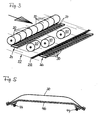
- Fig.1 is a slitter 10 of known type with two support rollers 12 shown in parallel to each other axes of rotation arranged in a common horizontal plane have, and the longitudinal knife 14 for dividing a wide Paper web 16 are connected upstream.
- the longitudinal knife 14 are like Usually designed as cutting rollers, parallel to the axes the support rollers 12 adjustable and removable and by additional same longitudinal knife can be added, so that they the wide paper web 16 in a more or less large number able to cut individual paper webs 18.
- the single ones Paper webs 18 are each on the support rollers 12 Roll 20 wound and then, for example by lowering the support rollers 12, delivered to a runway 22, which is symbolized by an arrow and 1 to 2% gradient in the direction away from the slitter 10.
- a slitter 10 is also known Design shown that has only a single support roller 12 and again with longitudinal knives 14 for dividing one wide paper web 16 into individual paper webs 18 is.
- the individual paper webs 18 each a roll 20 wound, but each roll one
- a pair of bearing journals, not shown, which engage on their end faces is assigned such that the rollers 20 alternately to one and the other side of the support roller 12 against each other are staggered.
- closes on both sides of the roll cutter 10 each have a runway 22 which again a gradient of 1 to 2% in the direction of the slitter away.
- Each of the ramps 24 and 26 shown in Figure 3 has a slope, the opposite of that of the runway 22 and is larger in amount. At least the ramp 24 is, however so adjustable that its slope with that of the runway 22 matches in size and direction.
- Each of the ramps 24 and 26 has a variety of braking devices of the rollers 20, which are equidistant from each other are arranged such that on each of the rollers 20, depending on their length, two or more such devices can have a braking effect.
- the device has a pillow 30 that extends from a portion of a Hose, for example fire hose, with a Length from approximately 400 to 600 mm or alternatively from two their edges welded or vulcanized flexible Plates can be formed from plastic or rubber.
- a Hose for example fire hose
- Length from approximately 400 to 600 mm or alternatively from two their edges welded or vulcanized flexible Plates can be formed from plastic or rubber.
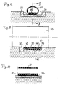
- the pillow 30 is at least at its edges in a tub-like Insert 32 attached, which in turn in the runway 22 is embedded, for example according to FIG the ramps 24 or 26 belonging to the runway 22 32 has, in longitudinal section according to Figure 4, but also in cross section 6 and 7, for example, considered a U-shaped Indentation 34 in which the cushion 30 is embedded in this way is that it comes even from the hardest occurring Rollers 20 that roll over the pillow are not pinched or otherwise be damaged.
- the cushion 30 is under a fluid, preferably air such pressure that it is filled by a roller 20, according to 4 rolls over the pillow in the direction of arrow A, divided into two hermetically separated chambers is, namely a first chamber 36 that has already been overrun is, and a second chamber 38, which is still overrun will be.
- the two chambers 36 and 38 are together connected by an overflow channel 40, one by hand contains adjustable or automatically adjustable throttle point 42.
- an overflow channel 40 is the pillow 30 with respect to the direction of movement A of the roller 20 each front and rear end area with a nipple 44.
- roller 20 in FIG. 4 is one of the three in FIG Figure 3 individually shown roles that are in the figure 3 are approaching the conveyor 28.
- the one shown in Fig.4 Roll 20 is over conveyor 28 to the second Rolled up ramp 26, which is a gradient contrary to the previous one Direction of movement of this role.
- the roller 20 displaces air from the front your lying second chamber 38, and this air flows through the overflow channel 40 and its throttle point 42 in the first Chamber 36.
- kinetic energy of the roll 20 is first into flow energy, and turns it into heat; the movement of the roller 20 is thus depending on the setting of the Throttle point 42 more or less braked.
- This Braking can be set so that the Roller 20 comes to a stop before moving cushion 30 towards completely rolled over from left to right in Fig. 4 Has.
- the throttling is preferably set so that the Slope of the second ramp 26 is just sufficient, the role 20 once their original movement has stopped is to slowly roll back onto the conveyor 28.
- the trough-like insert shown in Figure 4 32 be replaced by a plate-shaped base 46, which is slightly bent down at the front and back; the Nipples 44 are arranged in the area of the folds.
- pillow 30 of the type shown in Figure 5 can, for example, as self-supporting bridges between abutments of a supporting structure be arranged.
- FIGS. 6 and 7 show how this is tubular Pillow 30 expediently with respect to the insert 32 U-shaped recess 34 is dimensioned.
- the pillow 30 has according to 6 shows a circular cross section in the unloaded state, 7 of the one rolling over the pillow Roller 20 completely flattened, but by the The edges of the insert 32 are protected from being crushed become. 6 and 7 it is assumed that the pillow 30th in the area of its front and rear end at the insert 32 is attached, approximately as shown in Figure 4 is.
- Fig. 8 to 10 show another type of attachment in turn tubular pillow 30, but here in its lower Area between a two-layer base 46 in like a Velcro fastener and a plate-like one Insert 48 is arranged.
- the top layer of pad 46 and the insert 48 can both be glued to the pillow 30 or vulcanized or through its lower area riveted or screwed together.
- the lower one Layer of the base 46 is at the bottom of the recess 34 of the insert 32 attached, for example glued. It is essential that the insert 48 in accordance with FIG Roll 20 compressed state of the cushion 30 internal Overflow channels 40 leaves free, in which a throttled fluid flow between the two chambers 36 and 38 is possible.
- FIGS. 11 and 12 A similar effect can also be achieved according to FIGS. 11 and 12 Achieve plate-like inlay, if one on its longitudinal edges flattened, e.g. beveled support 46 is provided is. Both in Fig. 8 to 10 on the one hand and in Fig. 11 and 12 embodiments shown on the other hand is also common, that they can do without an external overflow channel. Indeed the base 46 and / or the insert 48 must be dimensioned in this way be that those remaining with the pillow 30 flattened internal overflow channels 40 a the respective purpose have adapted throttling effect.
- Figs. 13 and 14 One way of throttling the direction of movement to make the roller 20 dependent is in Figs. 13 and 14 shown.
- an external overflow channel 40 provided, however, in contrast to Figure 4 two throttling points 42 and 42 ', one behind the other and parallel are arranged to one check valve 50 or 50 '.
- the check valve 50 opposes a flow of right to left, forcing the roller to move 20 from left to right that displaced from the second chamber 38 Fluid to flow through the restriction 42.
- the Check valve 50 ' opposes fluid flow from left to right and thus compels one Movement of the roller 20 from right to left from the first Chamber 36 displaced fluid through the restriction 42 ' stream.
- this is Cushion 30 constantly connected to a compressed air source 52, 13 and 14 via the overflow channel 40 Shut-off valve 54 and a pressure reducing valve 56.
- FIG. 15 there is also a separate pillow 30 Relief valve 58 connected, and between the shut-off valve 54 and the overflow channel 40 is a check valve 60 arranged.
- a circuit can, for example the cushions 30 on the first ramp 24 to be assigned to the Possibility to create individual rolls 20 of a litter selectively to continue rolling after the throw first overall from the first inclined against the rolling direction Ramp 24 stopped and then lowered this ramp has been that only those roles 20 move on can, in their trajectory essentially without resistance compressible pillows 30 lie.
- the pillow 30 in FIG. 16 is designed as well the pillow 30 shown in Figure 4; in Fig. 16, however for the reason mentioned the right chamber of the pillow as first chamber 36, and the left as second chamber 38, referred to.
- a major difference compared to the previously described Embodiments are that according to Fig.16 no overflow channel 40 is provided, neither an external another internal.
- the second chamber 38 is at one Throttle point 42 in the form of an adjustable throttle valve connected via the roller 20 from the second Chamber 38 displaced air is released into the open.
- the first Chamber 36 is via a throttle 42 ', a shut-off valve 54 and a pressure reducing valve 56 to a compressed air source 52 connected, from which the pillow 30 is refilled becomes. Between the throttle point 42 'and the shut-off valve 54 a check valve 60 is arranged, the one Prevents air from flowing out of the first chamber 36.
Landscapes
- Registering, Tensioning, Guiding Webs, And Rollers Therefor (AREA)
- Braking Arrangements (AREA)
Abstract
Description
- das Kissen auf der Rollbahn befestigt und von der Rolle überrollbar ist,
- das Kissen von der es überrollenden Rolle durch deren Gewicht in eine schon überrollte erste Kammer und eine noch nicht überrollte zweite Kammer unterteilbar ist, und
- die zweite Kammer über einen Kanal, der eine Drosselstelle enthält, von Fluid entlastbar ist.
- Fig. 1
- eine Schrägansicht eines ansich bekannten Doppeltragwalzen-Rollenschneiders,
- Fig. 2
- eine Schrägansicht eines ansich bekannten Einzeltragwalzen-Rollenschneiders,
- Fig. 3
- eine Schrägansicht eines Sortierdecks mit zahlreichen erfindungsgemäßen Vorrichtungen zum Bremsen von Rollen,
- Fig. 4
- einen vergrößerten Längsschnitt einer der in Fig.3 dargestellten erfindungsgemäßen Vorrichtungen im Zustand des Überrolltwerdens,
- Fig. 5
- eine Variante zu Fig.4, jedoch in unbelastetem Zustand,
- Fig. 6
- einen Querschnitt der in Fig.4 dargestellten erfindungsgemäßen Vorrichtung in unbelastetem Zustand,
- Fig. 7
- einen Querschnitt der in Fig.6 dargestellten Vorrichtung, jedoch in durch eine Rolle belastetem Zustand,
- Fig. 8
- einen Querschnitt einer gegenüber Fig.6 weitergebildeten erfindungsgemäßen Vorrichtung in unbelastetem Zu-Fig. 9 einen Querschnitt der in Fig.8 dargestellten Vorrichtung in durch eine Rolle belastetem Zustand,
- Fig.10
- den Längsschnitt X-X in Fig.8,
- Fig.11
- einen Querschnitt einer anderen gegenüber Fig.6 weitergebildeten Ausführungsform einer erfindungsgemäßen Vorrichtung in unbelastetem Zustand,
- Fig.12
- einen Querschnitt der in Fig.11 dargestellten Vorrichtung in durch eine Rolle belastetem Zustand,
- Fig.13
- eine schaltungstechnische Weiterbildung der in Fig.4 dargestellten erfindungsgemäßen Vorrichtung im Zustand des Überrolltwerdens,
- Fig.14
- die schaltungstechnisch wie in Fig.13 ausgestattete Vorrichtung nach dem Überrolltwerden,
- Fig.15
- eine schaltungstechnische Weiterbildung der in Fig.13 und 14 dargestellten Vorrichtung, im Zustand des Überrolltwerdens, und
- Fig.16
- eine weitere Variante zu Fig. 13, ebenfalls im Zustand des Überrolltwerdens.
Claims (12)
- Vorrichtung zum Bremsen von auf einer Rollbahn (22) abrollenden Rollen (20), insbesondere Papierrollen, mit einem Kissen (30), das ein Fluid enthält und durch Einwirkung einer Rolle (20) gegen den Widerstand des Fluids verformbar ist,
dadurch gekennzeichnet, daßdas Kissen (30) auf der Rollbahn (22) befestigt und von der Rolle (20) überrollbar ist,das Kissen (30) von der es überrollenden Rolle (20) durch deren Gewicht in eine schon überrollte erste Kammer (36) und eine noch nicht überrollte zweite Kammer (38) unterteilbar ist, unddie zweite Kammer (38) über einen Kanal, der eine Drosselstelle (42) enthält, von Fluid entlastbar ist. - Vorrichtung nach Anspruch 1,
dadurch gekennzeichnet, daß die Drosselstelle (42) einstellbar ist. - Vorrichtung nach Anspruch 1 oder 2,
dadurch gekennzeichnet, daß der die Drosselstelle (42) enthaltende Kanal ein Überströmkanal (40) ist, der die beiden Kammern (36, 38) miteinander verbindet. - Vorrichtung nach Anspruch 3,
dadurch gekennzeichnet, daß der Überströmkanal (40) zwei unabhängig voneinander einstellbare, hintereinander angeordnete Drosselstellen (42, 42') enthält, denen je eines von zwei in entgegengesetzten Strömungsrichtungen öffnenden Rückschlagventilen (50, 50') parallelgeschaltet ist. - Vorrichtung nach Anspruch 3,
dadurch gekennzeichnet, daß das Kissen (30) in mindestens einem streifenförmigen, bezogen auf die Bewegungsrichtung der Rollen (20) längsgerichteten Bereich (60) nicht ausreichend abgestützt ist, um vom Gewicht einer Rolle (20) in einer die Kammern (36, 38) vollständig voneinander trennenden Weise flachgedrückt zu werden, sodaß in diesem Bereich (60) der die beiden Kammern (36, 38) verbindende Überströmkanal (40) im Kissen (20) selbst ausgebildet ist. - Vorrichtung nach Anspruch 5,
dadurch gekennzeichnet, daß das Kissen (20) auf einer Unterlage (46) befestigt ist, die zwei voneinander abgewandte längsge- richtete Bereiche (60) des Kissens (30) unabgestützt läßt. - Vorrichtung nach einem der Ansprüche 1 bis 6,
dadurch gekennzeichnet, daß das Kissen (30) in einer U-förmigen Vertiefung (34) der Rollbahn (22) gegen Zerquetschtwerden geschützt angeordnet ist. - Vorrichtung nach Anspruch 7,
dadurch gekennzeichnet, daß die Vertiefung (34) in einem starren Einsatz (32) ausgebildet ist, der seinerseits in die Rollbahn (22) eingebettet ist. - Vorrichtung nach einem der Ansprüche 1 bis 8,
dadurch gekennzeichnet, daß das Kissen (30) eine steife Einlage (48) enthält - Vorrichtung nach einem der Ansprüche 1 bis 9,
dadurch gekennzeichnet, daß das Kissen (30) durch eine Unterlage (46) in der Art eines Klettverschlusses am Verrutschen gehindert ist. - Vorrichtung nach einem der Ansprüche 1 bis 10,
dadurch gekennzeichnet, daß das Kissen (30) über ein Absperrventil (54) an eine Druckluftquelle (52) angeschlossen ist. - Vorrichtung nach Anspruch 11,
dadurch gekennzeichnet, daß zwischen der Druckluftquelle (52) und dem Absperrventil (54) ein einstellbares Druckminderventil (56) angeordnet ist.
Applications Claiming Priority (2)
| Application Number | Priority Date | Filing Date | Title |
|---|---|---|---|
| DE2000164058 DE10064058A1 (de) | 2000-12-21 | 2000-12-21 | Vorrichtung zum Bremsen von Rollen, insbesondere Papierrollen |
| DE10064058 | 2000-12-21 |
Publications (2)
| Publication Number | Publication Date |
|---|---|
| EP1216945A2 true EP1216945A2 (de) | 2002-06-26 |
| EP1216945A3 EP1216945A3 (de) | 2004-05-26 |
Family
ID=7668305
Family Applications (1)
| Application Number | Title | Priority Date | Filing Date |
|---|---|---|---|
| EP01129226A Withdrawn EP1216945A3 (de) | 2000-12-21 | 2001-12-10 | Vorrichtung zum Bremsen von Rollen, insbesondere Papierrollen |
Country Status (2)
| Country | Link |
|---|---|
| EP (1) | EP1216945A3 (de) |
| DE (1) | DE10064058A1 (de) |
Cited By (1)
| Publication number | Priority date | Publication date | Assignee | Title |
|---|---|---|---|---|
| WO2014174151A1 (en) * | 2013-04-24 | 2014-10-30 | Sovellusmestarit Oy | Method and apparatus for receiving of a cylindrical body and the use of the method and the apparatus |
Family Cites Families (7)
| Publication number | Priority date | Publication date | Assignee | Title |
|---|---|---|---|---|
| US2562035A (en) * | 1948-07-14 | 1951-07-24 | United States Steel Corp | Devices for positioning and handling cylindrical articles |
| US4541578A (en) * | 1982-08-11 | 1985-09-17 | Murata Kikai Kabushiki Kaisha | Doffing apparatus in automatic winder |
| DE3609086A1 (de) * | 1986-03-18 | 1987-10-01 | Wifag Maschf | Vorrichtung zum be- bzw. entladen eines rollenstaenders einer rollenrotationsdruckmaschine mit bzw. von papierrollen |
| GB2209328B (en) * | 1987-09-03 | 1991-09-25 | Isowa Industry Co | Cardboard web feeding device for corrugator. |
| US5402980A (en) * | 1992-07-28 | 1995-04-04 | Champion International Corporation | Wound paper roll support apparatus |
| FI97126C (fi) * | 1994-09-21 | 1996-10-25 | Valmet Paper Machinery Inc | Menetelmä ja sovitelma muuton pysäyttämiseksi |
| DE19753871A1 (de) * | 1997-12-05 | 1999-06-17 | Voith Sulzer Papiertech Patent | Wickelvorrichtung für einen Rollenschneider |
-
2000
- 2000-12-21 DE DE2000164058 patent/DE10064058A1/de not_active Withdrawn
-
2001
- 2001-12-10 EP EP01129226A patent/EP1216945A3/de not_active Withdrawn
Cited By (4)
| Publication number | Priority date | Publication date | Assignee | Title |
|---|---|---|---|---|
| WO2014174151A1 (en) * | 2013-04-24 | 2014-10-30 | Sovellusmestarit Oy | Method and apparatus for receiving of a cylindrical body and the use of the method and the apparatus |
| CN105324321A (zh) * | 2013-04-24 | 2016-02-10 | 索维斯姆斯塔瑞塔有限公司 | 用于接收圆柱形物体的方法和装置及所述方法和装置的使用 |
| US9784331B2 (en) | 2013-04-24 | 2017-10-10 | Sovellusmestarit Oy | Method and apparatus for receiving of a cylindrical body and the use of the method and the apparatus |
| EP2989034B1 (de) * | 2013-04-24 | 2020-10-14 | Sovellusmestarit Oy | Verfahren zur aufnahme von papierrollen in der papierindustrie |
Also Published As
| Publication number | Publication date |
|---|---|
| DE10064058A1 (de) | 2002-07-04 |
| EP1216945A3 (de) | 2004-05-26 |
Similar Documents
| Publication | Publication Date | Title |
|---|---|---|
| DE3406719C2 (de) | ||
| AT401922B (de) | Wickelmaschine für bahnförmiges gut, insbesondere papier | |
| DE1017017B (de) | Vorrichtung zum Aufwickeln einer Material-, insbesondere Papierbahn | |
| DE2320158C3 (de) | Fördereinrichtung für Körper mit konvexer Oberfläche, z.B. Rollen | |
| DE60009844T2 (de) | Förderrichtungs-Umschaltvorrichtung in einem Rollenförderer | |
| DE3706834C2 (de) | ||
| DE10020909B4 (de) | Vorrichtung zur Förderung einer Vorratsrolle | |
| EP0161569A2 (de) | Vorrichtung zum Aufwickeln bzw.Abwickeln von kontinuierlich, vorzugsweise in Schuppenformation, anfallenden Druckprodukten | |
| DE4321314C2 (de) | Vorrichtung zum Be- und/oder Entladen von Containern | |
| DE1114377B (de) | Maschine zum Aufwickeln einer Material-, insbesondere Papierbahn auf Rollen | |
| EP1108669A2 (de) | Rollenwickelvorrichtung, insbesondere für eine Rollenschneidmaschine | |
| EP1216945A2 (de) | Vorrichtung zum Bremsen von Rollen, insbesondere Papierrollen | |
| EP0905070B1 (de) | Tragwalzen-Wickelmaschine | |
| EP1373111B1 (de) | Wickelmaschine zum aufwickeln einer materialbahn, insbesondere einer papier- oder kartonbahn, zu wickelrollen | |
| DE3237598C2 (de) | Angetriebener Rollenförderer mit druckfreier Staustrecke | |
| EP0623438B1 (de) | Beschickungseinrichtung für Kalander | |
| DE29613350U1 (de) | Belastungswalzenanordnung | |
| DE3812863A1 (de) | Rollenfoerderer | |
| DE3117464A1 (de) | Einrichtung zum entnehmen von walzstaeben aus einer stablage | |
| EP0933320A2 (de) | Rollenwickler | |
| EP0987204B1 (de) | Rollenwickeleinrichtung | |
| DE2759092C3 (de) | Einrichtung zur Bewegung von Gegenständen entlang einer beliebigen Bahn | |
| EP0972732B1 (de) | Rollenwickeleinrichtung | |
| CH673636A5 (de) | ||
| DE8708849U1 (de) | Doppeltragwalzen-Wickelmaschine |
Legal Events
| Date | Code | Title | Description |
|---|---|---|---|
| PUAI | Public reference made under article 153(3) epc to a published international application that has entered the european phase |
Free format text: ORIGINAL CODE: 0009012 |
|
| AK | Designated contracting states |
Kind code of ref document: A2 Designated state(s): AT BE CH CY DE DK ES FI FR GB GR IE IT LI LU MC NL PT SE TR |
|
| AX | Request for extension of the european patent |
Free format text: AL;LT;LV;MK;RO;SI |
|
| PUAL | Search report despatched |
Free format text: ORIGINAL CODE: 0009013 |
|
| AK | Designated contracting states |
Kind code of ref document: A3 Designated state(s): AT BE CH CY DE DK ES FI FR GB GR IE IT LI LU MC NL PT SE TR |
|
| AX | Request for extension of the european patent |
Extension state: AL LT LV MK RO SI |
|
| STAA | Information on the status of an ep patent application or granted ep patent |
Free format text: STATUS: THE APPLICATION IS DEEMED TO BE WITHDRAWN |
|
| 18D | Application deemed to be withdrawn |
Effective date: 20040701 |