EP1216955B1 - Procédé de réformage avec un système de brûleurs à flux thermique variable placé du côté latéral - Google Patents
Procédé de réformage avec un système de brûleurs à flux thermique variable placé du côté latéral Download PDFInfo
- Publication number
- EP1216955B1 EP1216955B1 EP01129328A EP01129328A EP1216955B1 EP 1216955 B1 EP1216955 B1 EP 1216955B1 EP 01129328 A EP01129328 A EP 01129328A EP 01129328 A EP01129328 A EP 01129328A EP 1216955 B1 EP1216955 B1 EP 1216955B1
- Authority
- EP
- European Patent Office
- Prior art keywords
- shell
- reaction chamber
- longitudinal axis
- burner
- interior region
- Prior art date
- Legal status (The legal status is an assumption and is not a legal conclusion. Google has not performed a legal analysis and makes no representation as to the accuracy of the status listed.)
- Expired - Lifetime
Links
Images




Classifications
-
- C—CHEMISTRY; METALLURGY
- C10—PETROLEUM, GAS OR COKE INDUSTRIES; TECHNICAL GASES CONTAINING CARBON MONOXIDE; FUELS; LUBRICANTS; PEAT
- C10G—CRACKING HYDROCARBON OILS; PRODUCTION OF LIQUID HYDROCARBON MIXTURES, e.g. BY DESTRUCTIVE HYDROGENATION, OLIGOMERISATION, POLYMERISATION; RECOVERY OF HYDROCARBON OILS FROM OIL-SHALE, OIL-SAND, OR GASES; REFINING MIXTURES MAINLY CONSISTING OF HYDROCARBONS; REFORMING OF NAPHTHA; MINERAL WAXES
- C10G9/00—Thermal non-catalytic cracking, in the absence of hydrogen, of hydrocarbon oils
- C10G9/14—Thermal non-catalytic cracking, in the absence of hydrogen, of hydrocarbon oils in pipes or coils with or without auxiliary means, e.g. digesters, soaking drums, expansion means
- C10G9/18—Apparatus
- C10G9/20—Tube furnaces
-
- B—PERFORMING OPERATIONS; TRANSPORTING
- B01—PHYSICAL OR CHEMICAL PROCESSES OR APPARATUS IN GENERAL
- B01J—CHEMICAL OR PHYSICAL PROCESSES, e.g. CATALYSIS OR COLLOID CHEMISTRY; THEIR RELEVANT APPARATUS
- B01J8/00—Chemical or physical processes in general, conducted in the presence of fluids and solid particles; Apparatus for such processes
- B01J8/02—Chemical or physical processes in general, conducted in the presence of fluids and solid particles; Apparatus for such processes with stationary particles, e.g. in fixed beds
- B01J8/06—Chemical or physical processes in general, conducted in the presence of fluids and solid particles; Apparatus for such processes with stationary particles, e.g. in fixed beds in tube reactors; the solid particles being arranged in tubes
- B01J8/062—Chemical or physical processes in general, conducted in the presence of fluids and solid particles; Apparatus for such processes with stationary particles, e.g. in fixed beds in tube reactors; the solid particles being arranged in tubes being installed in a furnace
-
- C—CHEMISTRY; METALLURGY
- C01—INORGANIC CHEMISTRY
- C01B—NON-METALLIC ELEMENTS; COMPOUNDS THEREOF; METALLOIDS OR COMPOUNDS THEREOF NOT COVERED BY SUBCLASS C01C
- C01B3/00—Hydrogen; Gaseous mixtures containing hydrogen; Separation of hydrogen from mixtures containing it; Purification of hydrogen; Reversible storage of hydrogen
- C01B3/02—Production of hydrogen; Production of gaseous mixtures containing hydrogen
- C01B3/32—Production of hydrogen; Production of gaseous mixtures containing hydrogen by reaction of gaseous or liquid organic compounds with gasifying agents, e.g. water, carbon dioxide or air
- C01B3/34—Production of hydrogen; Production of gaseous mixtures containing hydrogen by reaction of gaseous or liquid organic compounds with gasifying agents, e.g. water, carbon dioxide or air by reaction of hydrocarbons with gasifying agents
- C01B3/38—Production of hydrogen; Production of gaseous mixtures containing hydrogen by reaction of gaseous or liquid organic compounds with gasifying agents, e.g. water, carbon dioxide or air by reaction of hydrocarbons with gasifying agents using catalysts
- C01B3/384—Production of hydrogen; Production of gaseous mixtures containing hydrogen by reaction of gaseous or liquid organic compounds with gasifying agents, e.g. water, carbon dioxide or air by reaction of hydrocarbons with gasifying agents using catalysts with external heating of the catalyst
-
- B—PERFORMING OPERATIONS; TRANSPORTING
- B01—PHYSICAL OR CHEMICAL PROCESSES OR APPARATUS IN GENERAL
- B01J—CHEMICAL OR PHYSICAL PROCESSES, e.g. CATALYSIS OR COLLOID CHEMISTRY; THEIR RELEVANT APPARATUS
- B01J2208/00—Processes carried out in the presence of solid particles; Reactors therefor
- B01J2208/00008—Controlling the process
- B01J2208/00017—Controlling the temperature
- B01J2208/00504—Controlling the temperature by means of a burner
-
- B—PERFORMING OPERATIONS; TRANSPORTING
- B01—PHYSICAL OR CHEMICAL PROCESSES OR APPARATUS IN GENERAL
- B01J—CHEMICAL OR PHYSICAL PROCESSES, e.g. CATALYSIS OR COLLOID CHEMISTRY; THEIR RELEVANT APPARATUS
- B01J2208/00—Processes carried out in the presence of solid particles; Reactors therefor
- B01J2208/00796—Details of the reactor or of the particulate material
- B01J2208/00823—Mixing elements
- B01J2208/00831—Stationary elements
- B01J2208/0084—Stationary elements inside the bed, e.g. baffles
-
- C—CHEMISTRY; METALLURGY
- C01—INORGANIC CHEMISTRY
- C01B—NON-METALLIC ELEMENTS; COMPOUNDS THEREOF; METALLOIDS OR COMPOUNDS THEREOF NOT COVERED BY SUBCLASS C01C
- C01B2203/00—Integrated processes for the production of hydrogen or synthesis gas
- C01B2203/08—Methods of heating or cooling
- C01B2203/0805—Methods of heating the process for making hydrogen or synthesis gas
- C01B2203/0811—Methods of heating the process for making hydrogen or synthesis gas by combustion of fuel
-
- C—CHEMISTRY; METALLURGY
- C01—INORGANIC CHEMISTRY
- C01B—NON-METALLIC ELEMENTS; COMPOUNDS THEREOF; METALLOIDS OR COMPOUNDS THEREOF NOT COVERED BY SUBCLASS C01C
- C01B2203/00—Integrated processes for the production of hydrogen or synthesis gas
- C01B2203/08—Methods of heating or cooling
- C01B2203/0805—Methods of heating the process for making hydrogen or synthesis gas
- C01B2203/0811—Methods of heating the process for making hydrogen or synthesis gas by combustion of fuel
- C01B2203/0816—Heating by flames
-
- C—CHEMISTRY; METALLURGY
- C01—INORGANIC CHEMISTRY
- C01B—NON-METALLIC ELEMENTS; COMPOUNDS THEREOF; METALLOIDS OR COMPOUNDS THEREOF NOT COVERED BY SUBCLASS C01C
- C01B2203/00—Integrated processes for the production of hydrogen or synthesis gas
- C01B2203/08—Methods of heating or cooling
- C01B2203/0805—Methods of heating the process for making hydrogen or synthesis gas
- C01B2203/0866—Methods of heating the process for making hydrogen or synthesis gas by combination of different heating methods
Definitions
- This invention relates to processes involving the heating of fluids, such as processes for the production of a gas containing hydrogen and carbon oxides by steam reforming a hydrocarbon feedstock, and in particular to an apparatus and method for hydrocarbon reforming processes, hydrocarbon cracking processes, and heating of fluids.
- the steam reforming process is a well known chemical process for hydrocarbon reforming.
- a hydrocarbon and steam mixture (a mixed-feed) reacts in the presence of a catalyst to form hydrogen, carbon monoxide and carbon dioxide. Since the reforming reaction is strongly endothermic, heat must be supplied to the reactant mixture, such as by heating the tubes in a furnace or reformer.
- the amount of reforming achieved depends on the temperature of the gas leaving the catalyst; exit temperatures in the range of 700° - 900 °C are typical for conventional hydrocarbon reforming.
- Figure 1 illustrates a conventional upflow, up-fired cylindrical reformer 10 (or furnace) having three burners 12 located therein. Tubes 14 are filled with catalyst and run the height of the reformer 10. A process fluid mixture enters through the inlet headers 18 and is injected into the tubes 14. The fluid mixture travels through the catalyst-filled tubes and exits to the outlet headers 16. The fluid mixture within the tubes is heated almost completely by radiant heat transfer from the burners 12 within the reformer. Only one side of the tube sees direct radiation from the flame, which results in non-uniform heating around the tube circumference. The flue gas exiting through the stack 15 is at a very high temperature.
- prior art hydrocarbon reforming processes use a tube within a tube (tube-in-tube) arrangement with catalyst in the annuli.
- the feed absorbs heat from the combustion side of the furnace through the outside tube wall.
- the reformed gas flow is reversed at the end of the catalyst bed and enters the inner-most passage of the tube. The reformed gas then gives up heat to the counter-current flow of the incoming cold feed.
- U.S. Pat. No. 3,230,052 discloses a terraced heater containing two rows of vertical catalyst-filled tubes (in a staggered arrangement).
- Each longitudinal wall of the furnace is made up of a series of planar surfaces that form a series of steps.
- the base of each step incorporates a series of troughs that run along the length of the furnace and incorporate (linear) burners.
- the burners inject flames into each trough to substantially fill each trough.
- the combustion is completed within the trough.
- the hot flue gases sweep over the inclined planar walls above each trough.
- the objective is to heat the inclined refractory wall to a (relatively) uniform temperature attempting to achieve a uniform heat intensity (heat flux) to the tubes in that section of the furnace.
- heat flux heat intensity
- U.S. Pat. No. 3,182,638 discloses a fired heater design that utilizes the same type of burners as disclosed in U.S. Pat. No. 3,230,052. Burners are located only on the floor. The furnace is divided into multiple cells using additional refractory faced walls. The object is to achieve a uniform heat flux to the serpentine tubes in each zone. The magnitude of heat transferred in each cell can be adjusted by controlling the fuel flow rate to each cell via trough burners firing along opposing walls.
- U.S. Pat. No. 5,199,961 (Ohsaki, et al .) discloses an apparatus for catalytic reaction having a lower radiant heat transfer space and an upper space designed to enhance convective heat transfer to the vertical tubular reactor.
- burner assemblies (called linear burners) are located along the furnace floor between rows of tubes. These burners fire upward along the vertical refractory walls. The intent is to distribute the heat to the tubes more evenly along the height of the tube and to attempt to provide approximately equal heat flow to each tubular reactor. The fuel is burned and releases its heat of combustion at only one elevation in the furnace.
- U.S. Pat. No. 2,751,893 discloses a radiant tubular heater and a method of heating.
- One object is to provide a method of achieving a uniform radiant heat flux around the circumference of the heater tube.
- the tube must be positioned in relation to a source of radiant heat in a manner to avoid direct impingement on the tube of the most intense part of the initial radiation and to distribute the radiant heat from the same source to opposite sides of the tubes by re-radiation from opposed radiating walls.
- the tubes are not in the line-of-sight of the burners.
- 2,751,893 is similar to that of the terraced heater in U.S. Pat. No. 3,230,052 in that both attempt to achieve a distribution of radiant heat along the length of the tubes. Both arrangements require many individual burners at different elevations and positions (along the circumference or length and along the height of the furnace).
- SRT Heater Technology developed by Lummus Company.
- This heater contains a single row of tubes in a serpentine coil arrangement that is fired on both sides with many burners (process stream flows across furnace). The objective is to achieve a high heat flux to maximize capacity. Recognizing that tube operation is limited by maximum tube metal temperature, the goal is to achieve a tube temperature profile that is as uniform as possible along the entire tube height. The burners are manifolded to permit control of firing rate separately at the outlet and inlet ends of the coil.
- the article states that this approach does not reduce the flue gas temperature in the upper part of the furnace, because doing so normally would result in lower heat absorption in that area. Therefore, the furnace is fired throughout the height in an attempt to produce a uniform heat flux over an entire zone of the furnace and the flue gas exits at a relatively high temperature.
- U.S. Pat. No. 4,959,079 discloses a furnace and process for reforming of hydrocarbons.
- the furnace consists of a radiant section and a convective section.
- the steam and hydrocarbon flow down through the catalyst-filled tube, first through the convective section and then through the radiant section.
- Fuel is fired in the radiant section and the combustion products flow counter-currently with the process gas in the convective section.
- the width is reduced (resulting in higher flue gas velocities) and extended surfaces (fins) are added to the reformer tube.
- U.S. Pat. No. 3,172,739 discloses an apparatus that comprises a natural-draft primary reforming furnace with an integral steam generator.
- the reforming furnace is cylindrical with reforming tubes arranged in a radial pattern inside an annulus.
- the central duct does not contain reformer tubes.
- a secondary burner fires into the central duct to provide for additional steam generation capability.
- Koniewiez does not discuss the problem of ensuring that (for each vertical slice of the furnace) each tube is heated uniformly around the circumference and that each tube segment receives the same amount of heat.
- Koniewiez also does not discuss the problem of ensuring that the amount of heat (heat flux) supplied to each segment of the tube does not cause the tube to overheat.
- U.S. Pat. No. 3,475,135 discloses a reforming furnace design with a rectangular enclosure. Vertical reformer tubes are placed in a zigzag arrangement between the longitudinal walls of the enclosure. Two rows of burners are located on the longitudinal walls. Process flow is downward and the flue gas flow is also downward (co-current flow).
- This furnace also contains a lower section designed to enhance convective heat transfer. In the convective section, the tubes are enclosed in channels to increase the flue gas velocity and the channels are filled with refractory pellets.
- This design approach applies side-fired, down-flow reforming with co-current flow (process gas and flue gas exit at bottom of furnace).
- U.S. Pat. No. 3,947,326 discloses a vertical tube type cracking furnace for ethylene and the like. Many burners are mounted along the side walls of the furnace to heat either one or two rows of vertical reaction tubes located between the sidewalls. The objective is to apply a uniform heat flux along the vertical tubes, which is not an optimal means to maximize thermal efficiency. (Optimizing thermal efficiency is not an objective of this patent, which teaches a method that actually results in a poor thermal efficiency.)
- U.S. Pat. No. 5,993,193 discloses a Variable Heat Flux Low Emissions Burner, which is provided with a plurality of fuel gas inlets for enabling manipulation of the flame shape and combustion characteristics of the burner based upon variation in the distribution of fuel gas between the various fuel gas inlets. The purpose of this is to vary the pattern of heat flux being produced when the burner apparatus is in operation.
- this burner is a circular burner with intricate design, apparently aimed at achieving a great degree of premixing and reduced NOx emissions. More importantly, the heat flux pattern of this burner is a longitudinal heat flux distribution along the flame. This type of burner is not capable of tailoring the heat release profile to match the process requirements.
- U.S. Pat. No. 5,295,820 (Bilcik, et al .) discloses a linear burner with a line of nozzles individually selected to operate by an electrically regulated distributor for the food industry. The intent is to have a burner with a wide range of heating power or turndown ratio.
- the invention is an apparatus and method for heating, reforming, or cracking hydrocarbon fluids or other fluids.
- the invention includes the use of a variable heat flux side-fired burner system for use in processes for heating, reforming, or cracking hydrocarbon fluids or other fluids.
- a first embodiment of the apparatus as defined in claim 1 includes: an elongated shell having an inner wall, a first end, and a second end opposite the first end; at least one elongated reaction chamber having a design temperature; a plurality of burners adjacent the inner wall; and transfer means adjacent the second end of the shell.
- the elongated shell has a first longitudinal axis, the shell being substantially symmetrical about the first longitudinal axis and enclosing a first interior region adjacent the first end and a second interior region adjacent the second end. Each of the first and second interior regions are substantially symmetrical about the first longitudinal axis.
- the at least one elongated reaction chamber has a second longitudinal axis substantially parallel to the first longitudinal axis.
- the reaction chamber is substantially symmetrical about the second longitudinal axis.
- a first portion of the reaction-chamber is disposed in the first interior region of the shell, and a second portion of the reaction chamber is disposed in the second interior region of the shell.
- the first and second portions of the reaction chamber are adapted to contain a flow of the process fluid.
- Each of the burners is adapted to combust at least one fuel, thereby producing a flue gas in the first interior region of the shell and a variable heat flux.
- the variable heat flux substantially approximates the process heat requirement and simultaneously maximizes the heat flux to substantially all of the first portion of the reaction chamber while maintaining substantially all of the first portion substantially at the design temperature without substantially exceeding the design temperature.
- At least a portion of the flow of the flue gas flows from the first interior region of the shell to the second interior region of the shell via the transfer means. At least a portion of the process fluid flows through at least the first or second portion of the reaction chamber counter-currently with at least a portion of the flow of the flue gas.
- the reaction chamber(s), which preferably is a tubular device is a reformer tube.
- the tubular device may be a reformer radiant tube or a tube-in-tube device.
- a substantial portion of the reaction chamber is substantially vertical within the shell.
- a flame is radially directed from the burner substantially toward the first longitudinal axis of the shell.
- the shell is substantially cylindrical.
- the shell may have other shapes.
- the shell has a cross-sectional area substantially in the form of an ellipse.
- the shell has a cross-sectional area substantially in the form of a polygon.
- Another embodiment of the invention is similar to the first embodiment of the apparatus but includes at least one refractory wall disposed in the shell adjacent the burner.
- the refractory wall is substantially perpendicular to the inner wall of the shell.
- Yet another embodiment of the invention similar to the first embodiment of the apparatus has a particular burner arrangement using a plurality of elongated burner assemblies adjacent the inner wall.
- Each of the burner assemblies has a different longitudinal axis substantially parallel to the first and second longitudinal axes, a first end, and a second end opposite the first end.
- the first end of the burner assembly is adjacent the first end of the shell and the second end of the burner assembly is in the first region of the shell.
- the burner assemblies are substantially equally spaced apart peripherally around the inner wall and at least two neighboring burner assemblies are substantially equidistant from the reaction chamber.
- Each burner assembly is adapted to combust at least one fuel, thereby generating a flue gas in the first interior region of the shell.
- the reaction chamber(s), which preferably is a tubular device, is a reformer tube.
- the tubular device may be a reformer radiant tube or a tube-in-tube device.
- Yet another embodiment of the invention is similar to the first embodiment of the apparatus but has a plurality of rays of one or more elongated reaction chambers (which may be reformer tubes). Each ray is substantially perpendicular to the inner wall of the shell. The rays divide the cross-sectional area of the shell into a plurality of equally-sized sectors having substantially identical shapes. At least one burner is disposed in each sector.
- Each of the reaction chambers has a design temperature and a different longitudinal axis substantially parallel to the first longitudinal axis and is substantially symmetrical about the different longitudinal axis.
- a first portion of each reaction chamber is disposed in the first interior region of the shell and a second portion of each of the reaction chambers is disposed in the second interior region of the shell.
- the first and second portions of the reaction chambers are adapted to contain a flow of the process fluid. In all other respects, this embodiment is substantially the same as the first embodiment of the apparatus.
- Another aspect of the invention is a method for producing a product from a process for heating, reforming, or cracking hydrocarbon fluids or other fluids as defined in claim 12.
- the process may have a heat requirement for heating the process fluid.
- a first embodiment of the method includes multiple steps.
- the first step is to provide an elongated shell having an inner wall, a first longitudinal axis, a first end, and a second end opposite the first end.
- the shell is substantially symmetrical about the first longitudinal axis and encloses a first interior region adjacent the first end and a second interior region adjacent the second end.
- Each of the first and second interior regions is substantially symmetrical about the first longitudinal axis.
- the second step is to provide at least one elongated reaction chamber having a design temperature and a second longitudinal axis substantially parallel to the first longitudinal axis.
- the reaction chamber is substantially symmetrical about the second longitudinal axis.
- a first portion of the reaction chamber is disposed in the first interior region of the shell and a second portion of the reaction chamber is disposed in the second interior region of the shell.
- the first and second portions of the reaction chamber are adapted to contain a flow of the process fluid.
- a third step is to provide a plurality of burners adjacent the inner wall, each of the burners being adapted to combust a fuel.
- the fourth step is to combust at least one fuel in at least one of the burners, thereby producing a flue gas in the first region of the shell and a variable heat flux.
- the variable heat flux substantially approximates the process heat requirement and simultaneously maximizes the heat flux to substantially all of the first portion of the reaction chamber .while maintaining substantially all of the first portion substantially at the design temperature without substantially exceeding the design temperature.
- the fifth step is to transfer at least a portion of a flow of the flue gas from the first interior region of the shell to the second interior region of the shell.
- the sixth step is to feed at least a portion of the process fluid to the reaction chamber, wherein the portion of the process fluid absorbs at least a portion of the heat flux. At least a portion of the process fluid flows through at least the first or second portion of the reaction chamber counter-currently with at least a portion of the flow of the flue gas.
- the reaction chamber(s), which preferably is a tubular device is a reformer tube.
- the tubular device may be a reformer radiant tube or tube-in-tube device.
- a flame is radially directed from the burner substantially toward the first longitudinal axis of the shell.
- Another embodiment of the method is similar to the first embodiment of the method but includes an additional step.
- the additional step is to withdraw a stream of the product from the reaction chamber.
- Yet another embodiment of the method is similar to the first embodiment except for the third step and the use of a particular burner arrangement.
- a plurality of elongated burner assemblies are provided adjacent the inner wall.
- Each of the burner assemblies has a different longitudinal axis substantially parallel to the first and second longitudinal axes, a first end, and a second end opposite the first end.
- the first end of the burner assembly is adjacent the first end of the shell and the second end of the burner assembly is in the first region of the shell.
- the burner assemblies are substantially equally spaced apart peripherally around said inner wall and at least two neighboring burner assemblies are substantially equidistant from the reaction chamber.
- the burner assemblies are adapted to combust at least one fuel.
- this embodiment is substantially the same as the first embodiment of the method.
- the reaction chamber in this embodiment may be a reformer tube.
- Yet another embodiment of the method is similar to the first embodiment of the method except for the second step.
- a plurality of rays of one or more elongated reaction chambers are provided.
- Each ray is substantially perpendicular to the inner wall, and the rays divide the cross-sectional area of the shell into a plurality of equally-sized sectors having substantially identical shapes.
- Each of the reaction chambers has a design temperature and a different longitudinal axis substantially parallel to the first longitudinal axis.
- Each of the reaction chambers is substantially symmetrical about the different longitudinal axis.
- a first portion of the reaction chamber is disposed in the first interior region of the shell and a second portion of the reaction chamber is disposed in the second interior region of the shell.
- the first and second portions of the reaction chamber are adapted to contain a flow of the process fluid.
- at least one burner is disposed in each of the sectors. In all other respects, this embodiment is substantially the same as the first embodiment of the method.
- the invention is an apparatus and a method for an advanced reforming process using a variable heat flux side-fired burner system.
- the invention is not, however, limited to reforming applications.
- Persons skilled in the art will recognize that the apparatus, method, and burner system may be used in many other fired process heating applications, including but not limited to fluid heating and hydrocarbon cracking ( e . g ., ethylene cracking).
- the process uses a reformer (or furnace) that has the following features: an integrated side-fired burner that produces a prescribed variable heat flux profile tailored to the process to achieve maximum capacity and maximum thermal efficiency, and avoids coking at the tube inlet; firing on both sides of tubes in the lower region (adjacent the tube outlet) to maximize the heat flux without overheating the tube (in the fired region) and no firing in the upper region, with optimal radiant heat transfer between the process gas and the flue gas due to counter-current flow; radially-directed firing and process tube alignment for optimal heat transfer around the tube circumference; unique burner system design to provide continuous and linear firing with variable heat flux; and optional refractory walls that extend radially from the inner wall of the furnace toward the center of the furnace, wherein the burners fire on both sides of each refractory wall, which helps to achieve the optimal heat flux distribution to the tubes.
- a reformer or furnace
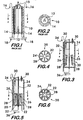
- Figures 3 and 4 show a schematic of the reformer 20 of the present invention (without optional refractory walls), and Figures 5 and 6 show a schematic of the reformer with optional refractory walls 22.
- the reformer 20 of the present invention includes a refractory lined shell 24.
- the shell is cylindrical.
- the cross-sectional area of the shell may have alternate shapes, such as a polygon ( e.g. , a triangle, square, rectangle, pentagon, hexagon, octagon, etc.), an ellipse, or other shapes.
- Multiple variable heat flux burners 26 are located adjacent the inner wall of the shell 24 near the lower end of the shell.
- the burners are recessed in the refractory lining of the inner wall. As shown in Figures 3 and 5, envelopes of the flames 28 are sheet-like. At the upper end of the shell (opposite the burner end), there are one or more openings 30 that allow the flue gas (containing combustion products) to flow from the shell.
- Conventional reformer tubes 32 containing catalyst are positioned within the interior of the shell to utilize high intensive radiant heat directly from the flames of the burners.
- the burners are equally spaced apart peripherally around the inner wall of the reformer, with neighboring burners being equidistant from one or more reformer tubes positioned in a vertical plane midway between the neighboring burners.
- burners may be arranged differently in other embodiments, one of which is illustrated in Figures 7-10.
- one or more burners 28 may be arranged within each of the (four) sectors of the reformer 20 to achieve the desired variable heat flux profile to the tubes 32 in the lower region of the reformer.
- multiple burners are fired in each pie-shaped sector ("quadrant") at different elevations on both sides of tubes arranged in a given ray of tubes.
- Figure 8 shows three burners firing within each quadrant and within a given slice of the reformer as a means of increasing the heat release rate within that slice of the furnace.
- Figure 9 shows two burners firing within each quadrant and within a given slice of the reformer as a means of increasing the heat release rate within that slice of the furnace.
- Figure 10 shows one burner firing within each quadrant and within a given slice of the reformer as a means of increasing the heat release rate within that slice of the furnace.
- the burners in Figures 7-10 are arranged as shown to ensure that the amount of heat that a given segment of each tube receives is approximately equal. (Persons skilled in the art will recognize that many burner arrangements other than that shown in Figures 7-10 are feasible. For example, one or more additional burners could be added in each sector at each elevation in Figures 8-10.)
- the tubes 32 are arranged in four sectors of the reformer 20 and one variable heat flux burner 28 is located at the inner wall in each sector, as shown in Figures 4 and 6.
- Each burner produces a substantially continuous flame along the height of the burner. The flame front only extends a short distance from the burner toward the centerline of the reformer. Heat is radiated directly from the flame and the burner tile to the tubes and is emitted and reflected from the inner wall.
- Mixed-feed enters the inlet header 34 and is distributed to the upper end of each reformer tube 32.
- Product synthesis gas exits at the lower end of each reformer tube and is removed from the reformer at the outlet header 36, and the flue gas exits from openings 30 at the top of the reformer.
- Figures 5 and 6 show a reformer that incorporates four vertical refractory walls 22, one in each sector.
- the hot flue gases (containing combustion products) flow radially across both sides of each refractory wall, which is thereby heated and radiates heat to the tubes.
- the refractory walls 22 are perpendicular to the inner wall of the shell 24.
- These refractory walls may be made of a composite of conventional refractory materials, such as high temperature fired bricks, or a solid casting of a refractory, such as alumina.
- Fuel is fired in the lower region of the reformer 20.
- the fuel is fired via the variable heat flux burners 26, which produce a prescribed heat flux profile along the tube length - - one that is tailored to the specific requirements of the process (reforming, or cracking, or other) taking place inside the tube.
- This prescribed heat flux profile simultaneously addresses constraints such as design tube metal temperature and coking, and maximizes average heat flux (capacity) and thermal efficiency.
- the heat flux profile produced by the variable heat flux burner 26 is designed to radiate the maximum amount of heat to each segment of the tube 32 in the fired zone without exceeding the tube design temperature limits.
- the objective is to provide the maximum possible heat flux through each tube segment that is located in the vicinity of the process outlet. (For reforming applications, the maximum heat flux is tied to the reforming reaction process that occurs as the gas flows through the tube.) As an intentional result, the tube wall temperature is maintained at a uniform value over most of the entire fired length of the tube.
- each variable heat flux burner 26 is located along the inner wall of the reformer 20 mid-way between two rays of tubes 32 (as illustrated in Figures 4 and 6), and an optional refractory wall 22 extends in the radial direction along the center line of each burner (as illustrated in Figure 6).
- the optional refractory walls are incorporated along the height of the fired region, but not in the unfired region. The refractory walls are used to ensure that the optimal heat flux distribution is attained in the fired region.
- each variable heat flux burner 26 fires fuel substantially continuously over the height of the reformer 20 occupied by the burner.
- the heat release intensity per unit length of the burner is very low and varies smoothly along the height of the burner.
- the firing rate per burner 26 can be varied for startup and operation at reduced production rates.
- An objective is to achieve the same relative heat release profile (% of total heat release versus burner height) over the burner capacity range. (Persons skilled in the art will recognize that an adjustable burner could be designed to vary the relative heat release profile.)
- the variable heat flux profile produced by the burner satisfies all of the constraints (e.g ., tube temperature, coking problem) over the turndown range. At turndown conditions, the tube wall temperature will again be similar to design conditions, only cooler.
- combustion products flow upward.
- the combustion products produced by the lower sections of the variable heat flux burners 26 combine with the combustion products produced by the upper sections of the burners and flow upward.
- the upper region of the reformer 20 is not fired.
- the flue gas (containing combustion products) flows counter-currently with the incoming process gas and exits at the top of the reformer. Counter-current flow helps to maximize the heat flux to the tubes in the upper region of the furnace by maximizing the temperature driving force.
- This arrangement helps to maximize throughput (capacity) while simultaneously achieving maximum possible radiant efficiency.
- the improvement in radiant efficiency at reduced rates will be even better than any improvement realized with co-current reforming technology.
- the burner and tile design, as well as the design layout of the reforming tubes 32, achieve a uniform heat flux at each elevation in the reformer 20, both around the circumference of individual tubes and from tube to tube.
- the ratio of the peak heat flux to the worst tube (tube with the maximum local heat flux at a given elevation) and the average heat flux to all the tubes at the same elevation is held as close to unity as possible.
- the optional refractory walls 22 further ensure that this challenging objective is met.
- Figure 11 plots the process duty-process temperature curve, also known as an S curve, for typical reformer tube design conditions (space velocity, catalyst size and shape, end-of-run catalyst activity). This plot is obtained from a steam methane reformer simulation program. At a given distance from the inlet of the tube, an amount of heat is transferred to the process gas that causes both the sensible and chemical enthalpy of the process gas to increase.
- the S curve plots the fraction of heat absorbed (from the inlet to a given point inside the tube) versus the process gas temperature at that point.
- the reformer tube is designed for a given operating life corresponding with specified limits on tube wall temperature and process pressure. Once the local conditions inside of the tube are known, it is possible to calculate the maximum local heat flux that the tube can sustain.
- Figure 12 plots the maximum heat flux as a function of the process temperature for the conditions corresponding to Figure 11.
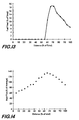
- Figure 13 illustrates the shape of the optimal firing profile for reforming natural gas with steam to produce hydrogen.
- This profile is for one specified design tube metal temperature and specific fixed process conditions.
- the reformer tubes are designed for one temperature and the process conditions of temperature and pressure are fixed, as is the capacity ( i . e ., fixed amounts of natural gas and steam are fed to the reformer).
- the amount of fuel fired per unit increment of reformer height tends to increase from a low value at the bottom of the reformer.
- the amount of fuel fired to the upper-most section of the burner tends to be less than the amount set by tube temperature constraints (reach target on total firing duty).
- Figure 14 shows the corresponding tube heat flux profile. In the fired region, the heat flux reaches the maximum heat flux limits as shown in Figure 12. In the unfired region, the heat fluxes are below these limits.
- Figure 15 plots the corresponding temperature profiles for flue gas, tube wall and process gas.
- the tube wall temperature is held at the design limits.
- the difference between the flue gas and tube wall temperatures is maximized and the temperature profiles do not pinch at the flue gas exit.
- FIGS 16-23 show several arrangements of the variable heat flux burner 26. (Persons skilled in the art will recognize that other burner arrangements are possible.)
- An important feature of the burner used in the preferred embodiment of the present invention is that it is a relatively long burner, preferably oriented in the vertical direction on the inner wall of the reformer 20. To be flexible, the burner may be divided into multiple sections, as shown in Figures 16-18. But all sections preferably share a common air supply 38 and a common fuel supply 40. This way, the piping, valves, and controls are simplified. Each section has a predetermined firing pattern. When joined together, the multi-section burner produces a heat release profile that optimally matches for the process conditions.
- each section has the same way of introducing fuel and air that produces a compact flame, similar to a conventional wall radiant burner. But it is stressed that Figures 16-18, show a single burner 26 with multiple sections, rather than multiple burners, because all sections share a common air supply 38, a common fuel supply 40, and a common burner control system (not shown).
- Figure 16 is a side view of one design of a variable heat flux burner 26 used in the present invention.
- Air 38 enters a conduit 42 at the bottom or top of the burner and air flow to each burner unit or section is regulated by a damper 44.
- a flame deflector 46 may be associated with each burner unit or section to shape the flame.
- Figure 17 provides a view of the burner without deflectors as viewed from inside the reformer 20.
- Figure 18 provides a view of the burner from outside of the reformer 20 showing the supply of fuel 40 to the individual burner units or sections via a distribution system including a manifold 48, piping 50 and control valves 52.
- Different types of burner tips may be used with the burner 26.
- Figure 19 is a schematic of one such burner tip 54
- Figure 20 is a schematic of another such burner tip 56.
- the flame 28 in the preferred embodiment has a sheet-like shape shown in Figure 3 and also in Figure 21.
- the sheet-like shape may be generated from a variable heat flux burner 26 such as that illustrated in Figures 16-18.
- a variable heat flux burner 26 such as that illustrated in Figures 16-18.
- other burner arrangements and flame shapes such as those shown in Figures 22 and 23, also may be used to generate the variable heat release pattern in the present invention.
- the burner units are equally spaced but each unit is designed to fire at a different firing rate to generate a variable heat release pattern.
- all burner units are designed to fire at the same firing rate and the spacing between burner units is varied to provide a variable heat release pattern.
- a variable burner unit spacing can also be combined with burner units designed to fire at different rates to achieve the prescribed heat flux profile.
- each burner unit in the preferred embodiment of the invention burns the same fuel
- different fuels may be used in alternate embodiments.
- selected burner units may be designed to fire a liquid fuel (such as naphtha) and other burner units may be designed to burn a gaseous fuel (such as the offgas produced from pressure swing adsorption).
- a mixture of fuels such as a mixture of natural gas and offgas from pressure swing adsorption.
Landscapes
- Chemical & Material Sciences (AREA)
- Chemical Kinetics & Catalysis (AREA)
- Organic Chemistry (AREA)
- Oil, Petroleum & Natural Gas (AREA)
- Engineering & Computer Science (AREA)
- General Chemical & Material Sciences (AREA)
- Physics & Mathematics (AREA)
- Thermal Sciences (AREA)
- Health & Medical Sciences (AREA)
- General Health & Medical Sciences (AREA)
- Combustion & Propulsion (AREA)
- Inorganic Chemistry (AREA)
- Hydrogen, Water And Hydrids (AREA)
- Heat-Exchange Devices With Radiators And Conduit Assemblies (AREA)
Claims (18)
- Appareil pour chauffer, reformer ou craquer des fluides hydrocarbures ou d'autres fluides dans un procédé ayant une exigence de chauffage de procédé pour chauffer un fluide de procédé dans le procédé, comprenant :une coque allongée (24) comportant une paroi interne, un premier axe longitudinal, une première extrémité et une seconde extrémité opposée à ladite première extrémité, ladite coque (24) étant sensiblement symétrique autour dudit premier axe longitudinal et enfermant une première région intérieure adjacente à la première extrémité et une seconde région intérieure adjacente à la seconde extrémité, chacune desdites première et seconde régions intérieures étant sensiblement symétriques autour dudit premier axe longitudinal ;au moins une chambre de réaction allongée (32) ayant une température de conception et un second axe longitudinal sensiblement parallèle audit premier axe longitudinal, ladite chambre de réaction (32) étant sensiblement symétrique autour dudit second axe longitudinal, une première portion de ladite chambre de réaction (32) étant disposée dans ladite première région intérieure de ladite coque (24) et une seconde portion de ladite chambre de réaction (32) étant disposée dans ladite seconde région intérieure de ladite coque (24), lesdites première et seconde portions de ladite chambre de réaction (32) étant adaptées pour contenir un écoulement dudit fluide de procédé ;une pluralité de brûleurs (26) adjacents à ladite paroi interne dans la première région intérieure, chacun desdits brûleurs (26) étant adapté pour brûler au moins un carburant, produisant ainsi des gaz brûlés dans ladite première région intérieure de ladite coque (24) ; ladite combustion se produisant adjacente à la sortie de la chambre de réaction (32), de telle sorte qu'au moins une portion dudit fluide de procédé s'écoule à travers au moins la première ou seconde portion de ladite chambre de réaction (32) à contre-courant avec au moins une portion dudit écoulement desdits gaz brûlés ; etdes moyens de transfert adjacents à la seconde extrémité de ladite coque (24), moyennant quoi au moins une portion d'un écoulement desdits gaz brûlés s'écoule de la première région intérieure de ladite coque (24) à la seconde région intérieure de ladite coque (24),ladite pluralité de brûleurs (26) étant adaptés pour produire un flux de chaleur variable approximant sensiblement ladite exigence de chauffage de procédé et maximisant simultanément ledit flux de chaleur à quasiment toute ladite première portion de ladite chambre dé réaction (32) tout en maintenant quasiment toute la première portion sensiblement à ladite température de conception sans excéder sensiblement ladite température de conception.
- Appareil selon la revendication 1, dans lequel une portion substantielle de ladite chambre de réaction (32) est sensiblement verticale à l'intérieur de ladite coque (24).
- Appareil selon la revendication 1, dans lequel ladite coque (24) est sensiblement cylindrique.
- Appareil selon la revendication 1, dans lequel ladite coque (24) a une aire en coupe transversale sensiblement de la forme d'une ellipse.
- Appareil selon la revendication 1, dans lequel ladite coque (24) est en forme de polygone en coupe transversale.
- Appareil selon la revendication 1, dans lequel une flamme est dirigée radialement à partir dudit brûleur (26) sensiblement vers ledit premier axe longitudinal de ladite coque (24).
- Appareil selon la revendication 1, comprenant en outre au moins une paroi réfractaire disposée dans ladite coque (24) adjacente audit brûleur, ladite paroi réfractaire étant sensiblement perpendiculaire à ladite paroi interne.
- Appareil selon la revendication 1, dans lequel la ou chaque chambre de réaction (32) est formée par un tube reformeur (32).
- Appareil selon la revendication 1, dans lequel ladite pluralité de brûleurs est formée par des ensembles de brûleur allongés (10) ayant un axe longitudinal différent sensiblement parallèle auxdits premier et second axes longitudinaux, une première extrémité, et une seconde extrémité opposée à ladite première extrémité, la première extrémité dudit ensemble de brûleur (26) étant adjacente à la première extrémité de ladite coque (24) et la seconde extrémité de l'ensemble de brûleur (26) étant dans ladite première région de ladite coque (24), ledit ensemble de brûleur (26) étant sensiblement espacé de manière égale périphériquement autour de ladite paroi interne et au moins deux ensembles de brûleurs voisins (26) étant sensiblement équidistants de ladite chambre de réaction.
- Appareil selon la revendication 9, dans lequel ladite chambre de réaction (32) est un tube reformeur (32).
- Appareil selon la revendication 1, dans lequel lesdites une ou plusieurs chambres de réaction allongées (32) fournissent une pluralité de rayons, chaque rayon étant sensiblement perpendiculaire à ladite paroi interne, lesdits rayons divisant ladite aire de coupe transversale en une pluralité de secteurs de tailles égales ayant des formes sensiblement identiques, chacune desdites chambres de réaction (32) ayant une température de conception et un axe longitudinal différent sensiblement parallèle audit premier axe longitudinal et étant sensiblement symétrique autour dudit axe longitudinal différent, et
dans lequel au moins un brûleur (26) est disposé dans chacun desdits secteurs. - Procédé de production d'un produit provenant d'un procédé pour chauffer, reformer ou craquer des fluides hydrocarbures ou d'autres fluides, le procédé ayant une exigence de chauffage de procédé pour chauffer un fluide de procédé, comprenant les étapes consistant à :fournir une coque allongée (32) comportant une paroi interne, un premier axe longitudinal, une première extrémité et une seconde extrémité opposée à ladite première extrémité, ladite coque (24) étant sensiblement symétrique autour dudit premier axe longitudinal et enfermant une première région intérieure adjacente à la première extrémité et une seconde région intérieure adjacente à la seconde extrémité, chacune desdites première et seconde régions intérieures étant sensiblement symétriques autour dudit premier axe longitudinal ;fournir au moins une chambre de réaction allongée (32) ayant une température de conception et un second axe longitudinal sensiblement parallèle audit premier axe longitudinal, ladite chambre de réaction (32) étant sensiblement symétrique autour dudit second axe longitudinal, une première portion de ladite chambre de réaction étant disposée dans ladite première région intérieure de ladite coque (24) et une seconde portion de ladite chambre de réaction (32) étant disposée dans ladite seconde région intérieure de ladite coque (24), lesdites première et seconde portions de ladite chambre de réaction (32) étant adaptées pour contenir un écoulement dudit fluide de procédé ;fournir une pluralité de brûleurs (26) adjacents à ladite paroi interne dans la première région intérieure, chacun desdits brûleurs (26) étant adapté pour brûler au moins un carburant ;brûler ledit au moins un carburant dans au moins un desdits brûleurs (26), produisant ainsi des gaz brûlés dans ladite première région de ladite coque (24) ; ladite combustion se produisant adjacente à la sortie de la chambre de réaction (32), de telle sorte qu'au moins une portion dudit fluide de procédé s'écoule à travers au moins la première ou seconde portion de ladite chambre de réaction (32) à contre-courant avec au moins une portion dudit écoulement desdits gaz brûlés ;transférer au moins une portion d'un écoulement desdits gaz brûlés de ladite première région intérieure de ladite coque (24) à ladite seconde région intérieure de ladite coque (24) ; etdélivrer au moins une portion dudit fluide de procédé à ladite chambre de réaction (32), ladite portion dudit fluide de procédé absorbant au moins une portion dudit flux de chaleur,en brûlant ledit au moins un carburant dans au moins un de ladite pluralité de brûleurs (26), un flux de chaleur variable est produit approximant sensiblement ladite exigence de chauffage de procédé et maximisant simultanément ledit flux de chaleur à quasiment toute ladite première portion de ladite chambre de réaction (32) tout en maintenant quasiment toute ladite première portion sensiblement à ladite température de conception sans excéder sensiblement ladite température de conception.
- Procédé selon la revendication 12, comprenant l'étape supplémentaire consistant à retirer un courant du produit de ladite chambre de réaction (32).
- Procédé selon la revendication 12, dans lequel une flamme est dirigée radialement dudit brûleur (26) sensiblement vers ledit premier axe longitudinal de ladite coque (24).
- Procédé selon la revendication 12, dans lequel la ou chaque chambre de réaction allongée (32) est formée par un tube reformeur.
- Procédé selon la revendication 12, comprenant l'étape additionnelle consistant à :fournir une pluralité d'ensembles de brûleur allongés (26) ayant chacun un axe longitudinal différent sensiblement parallèle auxdits premier et second axes longitudinaux, une première extrémité et une seconde extrémité opposée à ladite première extrémité, la première extrémité dudit ensemble de brûleur (29) étant adjacente à la première extrémité de ladite coque (24) et la seconde extrémité dudit ensemble de brûleur (26) étant dans ladite première région de ladite coque (24), lesdits ensembles de brûleur (26) étant sensiblement espacés de manière égale périphériquement autour de ladite paroi interne et au moins deux ensembles de brûleurs voisins (26) étant sensiblement équidistants de ladite chambre de réaction.
- Procédé selon la revendication 16, dans lequel la ou chaque chambre de réaction (32) est un tube reformeur.
- Procédé selon la revendication 12, comprenant l'étape additionnelle consistant à :fournir une pluralité de rayons d'une ou plusieurs chambres de réaction allongées (32), chaque rayon étant sensiblement perpendiculaire à ladite paroi interne, lesdits rayons divisant ladite aire en coupe transversale en une pluralité de secteurs de tailles égales ayant des formes sensiblement identiques, chacune desdites chambres de réaction (32) ayant une température de conception et un axe longitudinal différent sensiblement parallèle audit premier axe longitudinal et étant sensiblement symétrique autour dudit axe longitudinal différent, une première portion de chacune desdites chambres de réaction (32) étant disposée dans ladite première région intérieure de ladite coque (24) et une seconde portion de chacune desdites chambre de réaction (32) étant disposée dans ladite seconde région intérieure de ladite coque (24), lesdites première et seconde portions de ladite chambre de réaction (32) étant adaptées pour contenir un écoulement dudit fluide de procédé ;dans lequel au moins un brûleur (26) est disposé dans chacun desdits secteurs.
Applications Claiming Priority (2)
| Application Number | Priority Date | Filing Date | Title |
|---|---|---|---|
| US741284 | 2000-12-20 | ||
| US09/741,284 US20020110505A1 (en) | 2000-12-20 | 2000-12-20 | Reformer process with variable heat flux side-fired burner system |
Publications (3)
| Publication Number | Publication Date |
|---|---|
| EP1216955A2 EP1216955A2 (fr) | 2002-06-26 |
| EP1216955A3 EP1216955A3 (fr) | 2003-01-15 |
| EP1216955B1 true EP1216955B1 (fr) | 2006-02-15 |
Family
ID=24980104
Family Applications (1)
| Application Number | Title | Priority Date | Filing Date |
|---|---|---|---|
| EP01129328A Expired - Lifetime EP1216955B1 (fr) | 2000-12-20 | 2001-12-14 | Procédé de réformage avec un système de brûleurs à flux thermique variable placé du côté latéral |
Country Status (5)
| Country | Link |
|---|---|
| US (2) | US20020110505A1 (fr) |
| EP (1) | EP1216955B1 (fr) |
| AT (1) | ATE317833T1 (fr) |
| DE (1) | DE60117217T2 (fr) |
| ES (1) | ES2258504T3 (fr) |
Cited By (1)
| Publication number | Priority date | Publication date | Assignee | Title |
|---|---|---|---|---|
| EP2671634A1 (fr) | 2012-06-08 | 2013-12-11 | L'air Liquide, Societe Anonyme Pour L'etude Et L'exploitation Des Procedes Georges Claude | Procédé pour homogénéiser les températures de tube comprises entre tubes lors de procédés impliquant un chauffage d'écoulement des gaz dans les tubes |
Families Citing this family (12)
| Publication number | Priority date | Publication date | Assignee | Title |
|---|---|---|---|---|
| DE10111037A1 (de) * | 2001-03-08 | 2002-09-12 | Selas Linde Gmbh | Spaltofen |
| FR2880410B1 (fr) * | 2005-01-03 | 2007-03-16 | Air Liquide | Procede de combustion etagee produisant des flammes asymetriques |
| US20070234974A1 (en) * | 2006-04-10 | 2007-10-11 | The Cust-O-Fab Companies, Llc | Fired heater and flue gas tunnel therefor |
| FR2909445B1 (fr) | 2006-12-05 | 2009-02-06 | Air Liquide | Procede de controle d'une reaction de reformage par mesure de la temperature des tubes de reformage |
| US7578669B2 (en) * | 2006-12-14 | 2009-08-25 | Texaco Inc. | Hybrid combustor for fuel processing applications |
| DE102007019830B3 (de) * | 2007-04-25 | 2008-07-31 | Uhde Gmbh | Primärreformer mit brennerzuführenden Sekundäreinlasskanälen |
| FR2938251B1 (fr) * | 2008-11-13 | 2010-11-26 | Air Liquide | Procede d'allumage des bruleurs dans un four de reformage |
| ES2752674T3 (es) * | 2015-10-05 | 2020-04-06 | Air Liquide | Reformador de vapor para la producción de gas de síntesis |
| CA2912061C (fr) * | 2015-11-17 | 2022-11-29 | Nova Chemicals Corporation | Radiant a utiliser dans la section de radiants d'un generateur a feu direct |
| ES2941038T3 (es) * | 2019-11-13 | 2023-05-16 | Air Liquide | Horno reformador para llevar a cabo un proceso endotérmico |
| US20230158467A1 (en) | 2020-03-31 | 2023-05-25 | Technip Energies France Sas | Flameless Combustion Burner For An Endothermic Reaction Process |
| US20250136874A1 (en) * | 2023-10-27 | 2025-05-01 | Uop Llc | Processes and apparatuses for heating a hydrocarbon process stream |
Family Cites Families (16)
| Publication number | Priority date | Publication date | Assignee | Title |
|---|---|---|---|---|
| US2751893A (en) * | 1952-07-21 | 1956-06-26 | Shell Dev | Radiant tubular heater and method of heating |
| US3135314A (en) * | 1959-12-23 | 1964-06-02 | Sulzer Ag | Multiple fuel firing method and apparatus |
| US3172739A (en) * | 1962-02-06 | 1965-03-09 | Koniewiez | |
| US3182638A (en) * | 1963-02-19 | 1965-05-11 | Foster Wheeler Corp | Fired heater |
| BE646801A (fr) * | 1963-10-24 | 1964-10-20 | ||
| US3230052A (en) * | 1963-10-31 | 1966-01-18 | Foster Wheeler Corp | Terraced heaters |
| US3677234A (en) * | 1970-01-19 | 1972-07-18 | Stone & Webster Eng Corp | Heating apparatus and process |
| JPS5223632B2 (fr) * | 1973-03-22 | 1977-06-25 | ||
| US4092095A (en) * | 1977-03-18 | 1978-05-30 | Combustion Unlimited Incorporated | Combustor for waste gases |
| US4252300A (en) * | 1980-02-19 | 1981-02-24 | Prab Conveyors, Inc. | Burner control system |
| US4614491A (en) * | 1985-10-07 | 1986-09-30 | Welden David P | Multiple burner control apparatus |
| US4959079A (en) * | 1987-10-23 | 1990-09-25 | Santa Fe Braun Inc. | Steam reforming process with low fired duty |
| JPH04108533A (ja) * | 1990-08-28 | 1992-04-09 | Toyo Eng Corp | 触媒反応用装置 |
| FR2675242B1 (fr) * | 1991-04-15 | 1993-07-09 | Gaz De France | Bruleur lineaire. |
| US5417564A (en) * | 1994-01-27 | 1995-05-23 | Riley Stoker Corporation | Method and apparatus for altering the firing pattern of an existing furnace |
| US5993193A (en) * | 1998-02-09 | 1999-11-30 | Gas Research, Inc. | Variable heat flux low emissions burner |
-
2000
- 2000-12-20 US US09/741,284 patent/US20020110505A1/en not_active Abandoned
-
2001
- 2001-12-14 DE DE60117217T patent/DE60117217T2/de not_active Expired - Lifetime
- 2001-12-14 EP EP01129328A patent/EP1216955B1/fr not_active Expired - Lifetime
- 2001-12-14 AT AT01129328T patent/ATE317833T1/de not_active IP Right Cessation
- 2001-12-14 ES ES01129328T patent/ES2258504T3/es not_active Expired - Lifetime
-
2005
- 2005-03-07 US US11/074,031 patent/US20050158678A1/en not_active Abandoned
Cited By (2)
| Publication number | Priority date | Publication date | Assignee | Title |
|---|---|---|---|---|
| EP2671634A1 (fr) | 2012-06-08 | 2013-12-11 | L'air Liquide, Societe Anonyme Pour L'etude Et L'exploitation Des Procedes Georges Claude | Procédé pour homogénéiser les températures de tube comprises entre tubes lors de procédés impliquant un chauffage d'écoulement des gaz dans les tubes |
| WO2013182392A1 (fr) | 2012-06-08 | 2013-12-12 | L'air Liquide,Societe Anonyme Pour L'etude Et L'exploitation Des Procedes Georges Claude | Procédé d'homogénéisation des températures de tubes entre des tubes lors de traitements faisant appel à une chauffe de gaz circulant dans les tubes |
Also Published As
| Publication number | Publication date |
|---|---|
| ATE317833T1 (de) | 2006-03-15 |
| ES2258504T3 (es) | 2006-09-01 |
| DE60117217D1 (de) | 2006-04-20 |
| DE60117217T2 (de) | 2006-08-03 |
| EP1216955A2 (fr) | 2002-06-26 |
| US20020110505A1 (en) | 2002-08-15 |
| EP1216955A3 (fr) | 2003-01-15 |
| US20050158678A1 (en) | 2005-07-21 |
Similar Documents
| Publication | Publication Date | Title |
|---|---|---|
| JP3583780B2 (ja) | 吸熱反応装置および方法 | |
| US4692306A (en) | Catalytic reaction apparatus | |
| US8834586B2 (en) | Compact exchanger-reactor using a plurality of porous burners | |
| CN104620050B (zh) | 用于吸热反应的方法和装置 | |
| US3958951A (en) | Convective power reformer equipment and system | |
| US6835360B2 (en) | Compact endothermic catalytic reaction apparatus | |
| EP1216955B1 (fr) | Procédé de réformage avec un système de brûleurs à flux thermique variable placé du côté latéral | |
| EP1193219B1 (fr) | Dispositif et procédé pour le reformage d' hydrocarbure | |
| CN112585086B (zh) | 烃类的蒸汽重整或干重整 | |
| EP2830994B1 (fr) | Four de reformeur à vapeur et procédé pour celui-ci | |
| HUP0200615A2 (en) | Secondary reforming process and burner | |
| US6153152A (en) | Endothermic reaction apparatus and method | |
| CZ117696A3 (en) | Catalytic reaction vessel for endothermic reactions | |
| CA1091425A (fr) | Materiel et systeme de reformage par convection | |
| KR101526945B1 (ko) | 다관 원통형 수증기 개질기 | |
| US6395251B1 (en) | Steam-hydrocarbon reformer and process | |
| GB2314853A (en) | Reformer comprising finned reactant tubes | |
| JP2004137116A (ja) | 改質装置 | |
| KR20010049386A (ko) | 비단열공정을 실행하기 위한 반응기 | |
| WO1985003281A1 (fr) | Dispositif de chauffage par combustion pour la reformation a la vapeur |
Legal Events
| Date | Code | Title | Description |
|---|---|---|---|
| PUAI | Public reference made under article 153(3) epc to a published international application that has entered the european phase |
Free format text: ORIGINAL CODE: 0009012 |
|
| AK | Designated contracting states |
Kind code of ref document: A2 Designated state(s): AT BE CH CY DE DK ES FI FR GB GR IE IT LI LU MC NL PT SE TR |
|
| AX | Request for extension of the european patent |
Free format text: AL;LT;LV;MK;RO;SI |
|
| PUAL | Search report despatched |
Free format text: ORIGINAL CODE: 0009013 |
|
| AK | Designated contracting states |
Kind code of ref document: A3 Designated state(s): AT BE CH CY DE DK ES FI FR GB GR IE IT LI LU MC NL PT SE TR |
|
| AX | Request for extension of the european patent |
Free format text: AL;LT;LV;MK;RO;SI |
|
| 17P | Request for examination filed |
Effective date: 20030212 |
|
| 17Q | First examination report despatched |
Effective date: 20030417 |
|
| AKX | Designation fees paid |
Designated state(s): AT BE CH CY DE DK ES FI FR GB GR IE IT LI LU MC NL PT SE TR |
|
| GRAP | Despatch of communication of intention to grant a patent |
Free format text: ORIGINAL CODE: EPIDOSNIGR1 |
|
| GRAS | Grant fee paid |
Free format text: ORIGINAL CODE: EPIDOSNIGR3 |
|
| GRAA | (expected) grant |
Free format text: ORIGINAL CODE: 0009210 |
|
| AK | Designated contracting states |
Kind code of ref document: B1 Designated state(s): AT BE CH CY DE DK ES FI FR GB GR IE IT LI LU MC NL PT SE TR |
|
| PG25 | Lapsed in a contracting state [announced via postgrant information from national office to epo] |
Ref country code: BE Free format text: LAPSE BECAUSE OF FAILURE TO SUBMIT A TRANSLATION OF THE DESCRIPTION OR TO PAY THE FEE WITHIN THE PRESCRIBED TIME-LIMIT Effective date: 20060215 Ref country code: CH Free format text: LAPSE BECAUSE OF FAILURE TO SUBMIT A TRANSLATION OF THE DESCRIPTION OR TO PAY THE FEE WITHIN THE PRESCRIBED TIME-LIMIT Effective date: 20060215 Ref country code: LI Free format text: LAPSE BECAUSE OF FAILURE TO SUBMIT A TRANSLATION OF THE DESCRIPTION OR TO PAY THE FEE WITHIN THE PRESCRIBED TIME-LIMIT Effective date: 20060215 Ref country code: FI Free format text: LAPSE BECAUSE OF FAILURE TO SUBMIT A TRANSLATION OF THE DESCRIPTION OR TO PAY THE FEE WITHIN THE PRESCRIBED TIME-LIMIT Effective date: 20060215 Ref country code: AT Free format text: LAPSE BECAUSE OF FAILURE TO SUBMIT A TRANSLATION OF THE DESCRIPTION OR TO PAY THE FEE WITHIN THE PRESCRIBED TIME-LIMIT Effective date: 20060215 |
|
| REG | Reference to a national code |
Ref country code: CH Ref legal event code: EP Ref country code: GB Ref legal event code: FG4D |
|
| REG | Reference to a national code |
Ref country code: IE Ref legal event code: FG4D |
|
| REF | Corresponds to: |
Ref document number: 60117217 Country of ref document: DE Date of ref document: 20060420 Kind code of ref document: P |
|
| PG25 | Lapsed in a contracting state [announced via postgrant information from national office to epo] |
Ref country code: SE Free format text: LAPSE BECAUSE OF FAILURE TO SUBMIT A TRANSLATION OF THE DESCRIPTION OR TO PAY THE FEE WITHIN THE PRESCRIBED TIME-LIMIT Effective date: 20060515 Ref country code: DK Free format text: LAPSE BECAUSE OF FAILURE TO SUBMIT A TRANSLATION OF THE DESCRIPTION OR TO PAY THE FEE WITHIN THE PRESCRIBED TIME-LIMIT Effective date: 20060515 |
|
| PG25 | Lapsed in a contracting state [announced via postgrant information from national office to epo] |
Ref country code: PT Free format text: LAPSE BECAUSE OF FAILURE TO SUBMIT A TRANSLATION OF THE DESCRIPTION OR TO PAY THE FEE WITHIN THE PRESCRIBED TIME-LIMIT Effective date: 20060717 |
|
| REG | Reference to a national code |
Ref country code: CH Ref legal event code: PL |
|
| REG | Reference to a national code |
Ref country code: ES Ref legal event code: FG2A Ref document number: 2258504 Country of ref document: ES Kind code of ref document: T3 |
|
| ET | Fr: translation filed | ||
| PG25 | Lapsed in a contracting state [announced via postgrant information from national office to epo] |
Ref country code: IE Free format text: LAPSE BECAUSE OF NON-PAYMENT OF DUE FEES Effective date: 20061214 |
|
| PLBE | No opposition filed within time limit |
Free format text: ORIGINAL CODE: 0009261 |
|
| STAA | Information on the status of an ep patent application or granted ep patent |
Free format text: STATUS: NO OPPOSITION FILED WITHIN TIME LIMIT |
|
| PG25 | Lapsed in a contracting state [announced via postgrant information from national office to epo] |
Ref country code: MC Free format text: LAPSE BECAUSE OF NON-PAYMENT OF DUE FEES Effective date: 20061231 |
|
| 26N | No opposition filed |
Effective date: 20061116 |
|
| PG25 | Lapsed in a contracting state [announced via postgrant information from national office to epo] |
Ref country code: GR Free format text: LAPSE BECAUSE OF FAILURE TO SUBMIT A TRANSLATION OF THE DESCRIPTION OR TO PAY THE FEE WITHIN THE PRESCRIBED TIME-LIMIT Effective date: 20060516 |
|
| PG25 | Lapsed in a contracting state [announced via postgrant information from national office to epo] |
Ref country code: LU Free format text: LAPSE BECAUSE OF NON-PAYMENT OF DUE FEES Effective date: 20061214 Ref country code: TR Free format text: LAPSE BECAUSE OF FAILURE TO SUBMIT A TRANSLATION OF THE DESCRIPTION OR TO PAY THE FEE WITHIN THE PRESCRIBED TIME-LIMIT Effective date: 20060215 |
|
| PG25 | Lapsed in a contracting state [announced via postgrant information from national office to epo] |
Ref country code: CY Free format text: LAPSE BECAUSE OF FAILURE TO SUBMIT A TRANSLATION OF THE DESCRIPTION OR TO PAY THE FEE WITHIN THE PRESCRIBED TIME-LIMIT Effective date: 20060215 |
|
| PGFP | Annual fee paid to national office [announced via postgrant information from national office to epo] |
Ref country code: IT Payment date: 20121219 Year of fee payment: 12 Ref country code: GB Payment date: 20121128 Year of fee payment: 12 Ref country code: ES Payment date: 20121213 Year of fee payment: 12 |
|
| PGFP | Annual fee paid to national office [announced via postgrant information from national office to epo] |
Ref country code: FR Payment date: 20121219 Year of fee payment: 12 Ref country code: NL Payment date: 20121212 Year of fee payment: 12 |
|
| PGFP | Annual fee paid to national office [announced via postgrant information from national office to epo] |
Ref country code: DE Payment date: 20121221 Year of fee payment: 12 |
|
| REG | Reference to a national code |
Ref country code: DE Ref legal event code: R119 Ref document number: 60117217 Country of ref document: DE |
|
| REG | Reference to a national code |
Ref country code: NL Ref legal event code: V1 Effective date: 20140701 |
|
| GBPC | Gb: european patent ceased through non-payment of renewal fee |
Effective date: 20131214 |
|
| REG | Reference to a national code |
Ref country code: FR Ref legal event code: ST Effective date: 20140829 |
|
| REG | Reference to a national code |
Ref country code: DE Ref legal event code: R119 Ref document number: 60117217 Country of ref document: DE Effective date: 20140701 |
|
| PG25 | Lapsed in a contracting state [announced via postgrant information from national office to epo] |
Ref country code: NL Free format text: LAPSE BECAUSE OF NON-PAYMENT OF DUE FEES Effective date: 20140701 Ref country code: DE Free format text: LAPSE BECAUSE OF NON-PAYMENT OF DUE FEES Effective date: 20140701 |
|
| PG25 | Lapsed in a contracting state [announced via postgrant information from national office to epo] |
Ref country code: GB Free format text: LAPSE BECAUSE OF NON-PAYMENT OF DUE FEES Effective date: 20131214 Ref country code: FR Free format text: LAPSE BECAUSE OF NON-PAYMENT OF DUE FEES Effective date: 20131231 |
|
| REG | Reference to a national code |
Ref country code: ES Ref legal event code: FD2A Effective date: 20150327 |
|
| PG25 | Lapsed in a contracting state [announced via postgrant information from national office to epo] |
Ref country code: ES Free format text: LAPSE BECAUSE OF NON-PAYMENT OF DUE FEES Effective date: 20131215 |
|
| PG25 | Lapsed in a contracting state [announced via postgrant information from national office to epo] |
Ref country code: IT Free format text: LAPSE BECAUSE OF NON-PAYMENT OF DUE FEES Effective date: 20131231 |
|
| PG25 | Lapsed in a contracting state [announced via postgrant information from national office to epo] |
Ref country code: IT Free format text: LAPSE BECAUSE OF NON-PAYMENT OF DUE FEES Effective date: 20131214 |