EP1217100B1 - Dispositif de relevage du cadre anodique d'une cuve d'électrolyse pour la production d'aluminium - Google Patents
Dispositif de relevage du cadre anodique d'une cuve d'électrolyse pour la production d'aluminium Download PDFInfo
- Publication number
- EP1217100B1 EP1217100B1 EP00420261A EP00420261A EP1217100B1 EP 1217100 B1 EP1217100 B1 EP 1217100B1 EP 00420261 A EP00420261 A EP 00420261A EP 00420261 A EP00420261 A EP 00420261A EP 1217100 B1 EP1217100 B1 EP 1217100B1
- Authority
- EP
- European Patent Office
- Prior art keywords
- anode
- gripping
- lifting
- anode frame
- frame
- Prior art date
- Legal status (The legal status is an assumption and is not a legal conclusion. Google has not performed a legal analysis and makes no representation as to the accuracy of the status listed.)
- Expired - Lifetime
Links
- 238000004519 manufacturing process Methods 0.000 title claims abstract description 8
- 229910052782 aluminium Inorganic materials 0.000 title claims abstract description 7
- XAGFODPZIPBFFR-UHFFFAOYSA-N aluminium Chemical compound [Al] XAGFODPZIPBFFR-UHFFFAOYSA-N 0.000 title claims abstract description 7
- 239000004411 aluminium Substances 0.000 title claims abstract 3
- 238000005868 electrolysis reaction Methods 0.000 claims abstract description 16
- 238000003825 pressing Methods 0.000 claims abstract description 10
- 239000012190 activator Substances 0.000 claims description 6
- 230000009471 action Effects 0.000 claims description 4
- 230000004913 activation Effects 0.000 claims description 4
- 239000000470 constituent Substances 0.000 claims description 2
- 235000012771 pancakes Nutrition 0.000 claims 2
- 238000000926 separation method Methods 0.000 claims 1
- 210000000056 organ Anatomy 0.000 description 5
- OKTJSMMVPCPJKN-UHFFFAOYSA-N Carbon Chemical compound [C] OKTJSMMVPCPJKN-UHFFFAOYSA-N 0.000 description 3
- PNEYBMLMFCGWSK-UHFFFAOYSA-N aluminium oxide Inorganic materials [O-2].[O-2].[O-2].[Al+3].[Al+3] PNEYBMLMFCGWSK-UHFFFAOYSA-N 0.000 description 3
- 230000003042 antagnostic effect Effects 0.000 description 3
- 229910052799 carbon Inorganic materials 0.000 description 3
- 229910052751 metal Inorganic materials 0.000 description 3
- 239000002184 metal Substances 0.000 description 3
- 238000000034 method Methods 0.000 description 3
- 229910001610 cryolite Inorganic materials 0.000 description 2
- 230000000694 effects Effects 0.000 description 2
- 230000007246 mechanism Effects 0.000 description 2
- 238000007747 plating Methods 0.000 description 2
- 239000004809 Teflon Substances 0.000 description 1
- 229920006362 Teflon® Polymers 0.000 description 1
- 241001080024 Telles Species 0.000 description 1
- 230000006978 adaptation Effects 0.000 description 1
- 238000012550 audit Methods 0.000 description 1
- 238000006243 chemical reaction Methods 0.000 description 1
- 230000000295 complement effect Effects 0.000 description 1
- 230000006835 compression Effects 0.000 description 1
- 238000007906 compression Methods 0.000 description 1
- 238000010924 continuous production Methods 0.000 description 1
- 238000005520 cutting process Methods 0.000 description 1
- 230000007423 decrease Effects 0.000 description 1
- 230000008021 deposition Effects 0.000 description 1
- 238000006073 displacement reaction Methods 0.000 description 1
- 230000005611 electricity Effects 0.000 description 1
- 230000006355 external stress Effects 0.000 description 1
- 238000002513 implantation Methods 0.000 description 1
- 230000006872 improvement Effects 0.000 description 1
- 238000009434 installation Methods 0.000 description 1
- 239000011810 insulating material Substances 0.000 description 1
- 238000005304 joining Methods 0.000 description 1
- 238000012423 maintenance Methods 0.000 description 1
- 238000007726 management method Methods 0.000 description 1
- 238000005192 partition Methods 0.000 description 1
- -1 polytetrafluoroethylene Polymers 0.000 description 1
- 229920001343 polytetrafluoroethylene Polymers 0.000 description 1
- 239000004810 polytetrafluoroethylene Substances 0.000 description 1
- 230000008092 positive effect Effects 0.000 description 1
- 238000011084 recovery Methods 0.000 description 1
Images

Classifications
-
- C—CHEMISTRY; METALLURGY
- C25—ELECTROLYTIC OR ELECTROPHORETIC PROCESSES; APPARATUS THEREFOR
- C25C—PROCESSES FOR THE ELECTROLYTIC PRODUCTION, RECOVERY OR REFINING OF METALS; APPARATUS THEREFOR
- C25C3/00—Electrolytic production, recovery or refining of metals by electrolysis of melts
- C25C3/06—Electrolytic production, recovery or refining of metals by electrolysis of melts of aluminium
- C25C3/08—Cell construction, e.g. bottoms, walls, cathodes
- C25C3/10—External supporting frames or structures
Definitions
- the invention relates to the field of aluminum production by igneous electrolysis, in particular according to the HALL-HEROULT method, and more particularly the management of certain stages of the operation of the facilities for such production.
- It relates more particularly to a lifting device of the anode frame, it is to say of the organ carrying the different anodes within the same tank.
- These anodes in this case consist of carbon sealed on a conductive metal rod of electricity.
- the bottom of the tanks supports a cathode.
- the tanks generally comprise two horizontal conductive bars, generally called anode frames, supported by at least one rigid horizontal metal beam, adjustable in height.
- the carbon anodes are generally positioned along two parallel lines, and are supported by conductive rods releasably connected to each of the two anodic frames.
- the anode frame on which are fixed the anodes via the rods metal regularly decreases at the rate of carbon consumption constituent of the anode, by the chemical reaction of electrolysis, by means of of a mechanism implanted on the tank.
- the purpose of the descent of the anodes within the cryolite and alumina bath is keeping the air gap between the anode surface and the cathode substantially constant.
- this operation of raising of the anode frame must be carried out without interrupt the continuous process, including without cutting off the electrical current.
- the anodes mounted on the frame must be maintained at the height they had reached during the lifting operation of the framework, without ceasing to be in close and intimate contact with the said framework, in order to do not interrupt the continuity of the electric current.
- the invention proposes a solution to this problem, both simple to implement and effective in his action.
- the gripping and holding members are arranged on each side and other of the tank, and therefore on both sides of the portico.
- the pendulum movement of the modules pressure is ensured by means of an activator, and in particular a pneumatic cylinder, in the absence of the activation of which a return spring induces the plating of said pressure modules against the gantry, ie canceling any pendulum movement, and as a result, a plating of the anode rods against the anode frame.
- the gripping module is constituted a clamp located at the lower end of the gripping and holding member, said clamp being open under the action of an activator, and in particular a jack pneumatic in the absence of whose activation, a spring induces its closure on said anode rod.
- the gripping module is capable of to be the object of pendular movements, but this time in the plane of the stems anode on the same side of the tank.
- FIG. 1 shows an igneous electrolysis cell (21), within which from which plunge a series of anodes (24). These anodes are electrically connected to anode frame (23), via a conductive rod (12), substantially vertical, further ensuring the function of maintaining the anodes.
- the anode frame (23) is capable of translating vertically with respect to a frame (22) extending above the tank. During this translation, by means of a lifting beam of the anode frame (not shown) the anode frame causes the anodes (24) which are secured to it.
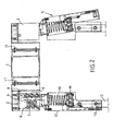
- FIG. 2 shows the device according to the invention.
- a gantry (1) substantially symmetrical, and intended to be positioned above each of the electrolysis tanks.
- This gantry is for example, moved from one tank to another, by means of one or two lift trucks, which are provided with the upper decks in the aluminum production facilities.
- This gantry (1) has at its two ends zones (2) and (3) articulation a plurality of gripping and holding members (5) of the anode rods.
- gripping members (5) there are as many gripping members (5) as there are anodes and as can be seen in FIG. 2, these gripping members are distributed on both sides other of the tank.
- This gantry (1) intended to rest on the tank, is electrically isolated from grippers (5) by means of intermediate elements (11) made in one insulating material, typically polytetrafluoroethylene (Teflon - registered trademark).
- the gripping members (5) first of all comprise a presser module, capable of being animated by a partial rotation movement relative to the hinge axis (4), according to a plane perpendicular to the plane containing the anode rods on the same side of the tank.
- the presser module is maintained vertical via a calibrated spring (7), respectively taking bearing against the outer wall (6) of the zones respectively (2) and (3), and against the piece link (8), joining the articulation axis (4) of the gripping member (5) well said.
- the spacing of said module from its vertical position is ensured by means of a pneumatic cylinder of the type flexible cylinder slab (9), taking bearing against the internal partition (10) of the zones respectively (2) and (3) and against connecting piece (8), as can be seen in Figure 2.
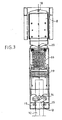
- the gripping module of the anode rods (12) consists of a gripper (13), whose the two parts are articulated in (14), so as to allow the approximation of gripping areas (15) of the clamp from each other, and thus to ensure the function of tightening and gripping the rods (12).
- a spring (16) with vertical action, integrated in the body (17) of the gripping member (5) ensures the approximation of the elements of gripping (15) from one another, and thus holds the clamp (13) in the clamping position.
- the particular architecture of the device according to the invention, and in particular the position of the actuators above the anode rods (12) allows to release the four lateral faces of the organ (5), thus freeing the mechanism of the constraints right or left of each of the actuators, these constraints being imposed by positive climb (electrical current) arrivals at the level of anodic frame. It allows corollary to implement two functions complementary of improvement of the electrical contact anode rod - anode frame, the operation is done just before loosening the connectors, and just after the tightening the connectors, assuring as already said, fixing the rods on the frame anodic.
- the lifting beam according to the invention also has a certain modularity, thus likely to make it adaptable to different morphologies of tank.
- the gripping and holding members (5) are adjustable in terms of fixation on the gantry (1) constituting the lifting beam.
- the gripping modules are also likely to represent a pendulum movement in the plane of the rods anodic.
- the pendular system (18) is free of any constraint, on the other hand the system (20) is adjustable by means of springs and screw, so as to allow a lateral deflection of the order of 20 to 30 mm. This allows a greater tolerance of adaptation of the gripping modules at the level of anode rods.
Landscapes
- Chemical & Material Sciences (AREA)
- Engineering & Computer Science (AREA)
- Chemical Kinetics & Catalysis (AREA)
- Electrochemistry (AREA)
- Materials Engineering (AREA)
- Metallurgy (AREA)
- Organic Chemistry (AREA)
- Electrolytic Production Of Metals (AREA)
- Electrolytic Production Of Non-Metals, Compounds, Apparatuses Therefor (AREA)
Description
- un portique horizontal, destiné à venir se positionner au dessus de la cuve en question ;
- une pluralité d'organes de préhension et de maintien des tiges d'anode contre le
cadre anodique, comprenant :
- un module presseur, articulé au niveau de son extrémité supérieure sur ledit portique, afin de pouvoir subir un déplacement pendulaire par rapport audit portique, de telle sorte à s'écarter du plan contenant les tiges d'anodes d'un même côté de la cuve, et destiné à assurer le maintien des tiges d'anode contre le cadre anodique ;
- et un module de préhension, solidaire du module presseur, et destiné à assurer la préhension effective d'une tige d'anode.
Fondamentalement, celui-ci est constitué d'un portique (1), sensiblement symétrique, et destiné à venir se positionner au dessus de chacune des cuves d'électrolyse. Ce portique est par exemple, déplacé d'une cuve à l'autre, au moyen d'un ou de deux chariots de levage, dont sont munis les ponts supérieurs dans les installations de production d'aluminium.
- dépôt de la poutre de relevage sur le dessus de la cuve considérée :
- application d'un effort presseur sur les tiges d'anode (12) contre le cadre anodique, afin de maintenir la continuité électrique ;
- préhension des tiges d'anode par les modules de préhension ;
- desserrage des connecteurs assurant la fixation des tiges d'anode sur le cadre anodique ;
- remontée du cadre anodique ;
- resserrage desdits connecteurs sur les tiges ;
- arrêt de la fonction préhension et serrage des tiges d'anode ;
- enlèvement de la poutre de relevage.
Claims (11)
- Dispositif de relevage du cadre anodique d'une cuve d'électrolyse pour la production d'aluminium caractérisé en ce qu'il comprend :un portique horizontal (1), destiné à venir se positionner au dessus de la cuve en question ;une pluralité d'organes de préhension et de maintien (5) des tiges (12) d'anode contre le cadre anodique, comprenant :un module presseur, articulé (4) au niveau de son extrémité supérieure sur ledit portique, afin de pouvoir subir un déplacement pendulaire par rapport audit portique, de telle sorte à s'écarter du plan contenant les tiges d'anodes d'un même côté de la cuve, et destiné à assurer le maintien des tiges d'anode contre le cadre anodique ;et un module de préhension, solidaire du module presseur, et destiné à assurer la préhension effective d'une tige d'anode.
- Dispositif de relevage du cadre anodique d'une cuve d'électrolyse selon la revendication 1, caractérisé en ce que les organes de préhension et de maintien (5) sont disposés de part et d'autre de la cuve, et donc de part et d'autre du portique (1).
- Dispositif de relevage du cadre anodique d'une cuve d'électrolyse selon l'une des revendications 1 et 2, caractérisé en ce que les organes de préhension et de maintien (5) sont fixés au portique selon un écartement fonction de l'entraxe standard des tiges (12) d'anodes pour une installation considérée.
- Dispositif de relevage du cadre anodique d'une cuve d'électrolyse selon l'une des revendications 1 à 3, caractérisé en ce que le mouvement pendulaire des modules presseur est assuré au moyen d'un activateur (9), en l'absence de l'activation duquel un ressort de rappel (7) induit le placage desdits modules presseur contre le portique, c'est à dire annulant tout mouvement pendulaire, et par voie de conséquence, un placage des tiges d'anodes contre le cadre anodique.
- Dispositif de relevage du cadre anodique d'une cuve d'électrolyse selon la revendication 4, caractérisé en ce que l'activateur est un vérin pneumatique (9) du type galette souple.
- Dispositif de relevage du cadre anodique d'une cuve d'électrolyse selon l'une des revendications 1 à 5, caractérisé en ce que le module de préhension est constitué d'une pince (13), positionnée à l'extrémité inférieure de l'organe de préhension et de maintien (5), ladite pince étant ouverte sous l'action d'un activateur (19), en l'absence de l'activation duquel, un ressort (17) induit sa fermeture sur ladite tige d'anode (12).
- Dispositif de relevage du cadre anodique d'une cuve d'électrolyse selon la revendication 6, caractérisé en ce que l'activateur est un vérin pneumatique (19) du type galette souple tri - lobes.
- Dispositif de relevage du cadre anodique d'une cuve d'électrolyse selon l'une des revendications 1 à 7, caractérisé en ce que le module de préhension est susceptible de faire l'objet de mouvements pendulaires, dans le plan des tiges d'anode (12), d'un même coté de la cuve.
- Dispositif de relevage du cadre anodique d'une cuve d'électrolyse selon la revendication 8, caractérisé en ce que le module de préhension dispose d'un double point d'articulation, respectivement en partie supérieure (18) et en partie intermédiaire (20), les axes d'articulation correspondant étant solidaires du châssis constitutif des organes (5), de telle sorte à permettre un débattement latéral du module de préhension, et ainsi de disposer d'une plus grande tolérance d'adaptation dudit module au niveau des tiges d'anode.
- Dispositif de relevage du cadre anodique d'une cuve d'électrolyse selon la revendication 9, caractérisé en ce que le système pendulaire supérieur (18) est libre, c'est à dire exempt de toute contrainte, et en ce que le système pendulaire interrnédiaire (20) est réglable au moyen de ressorts et vis.
- Dispositif de relevage du cadre anodique d'une cuve d'électrolyse selon l'une des revendications 1 à 10, caractérisé en ce qu'à chaque module presseur est associé deux modules de préhension des tiges d'anode.
Priority Applications (10)
| Application Number | Priority Date | Filing Date | Title |
|---|---|---|---|
| AT00420261T ATE307916T1 (de) | 2000-12-19 | 2000-12-19 | Anhebevorrichtung für den anodenträger in elektrolyseöfen für die aluminiumherstellung |
| EP00420261A EP1217100B1 (fr) | 2000-12-19 | 2000-12-19 | Dispositif de relevage du cadre anodique d'une cuve d'électrolyse pour la production d'aluminium |
| SI200030776T SI1217100T1 (sl) | 2000-12-19 | 2000-12-19 | Dvigovalna priprava za anodni nosilec v elektroliznih kadeh za pridobivanje aluminija |
| ES00420261T ES2248032T3 (es) | 2000-12-19 | 2000-12-19 | Dispositivo de elevacion del marco anodico de una cuba de electrolisis para la produccion de aluminio. |
| DE60023530T DE60023530D1 (de) | 2000-12-19 | 2000-12-19 | Anhebevorrichtung für den Anodenträger in Elektrolyseöfen für die Aluminiumherstellung |
| NO20015496A NO20015496L (no) | 2000-12-19 | 2001-11-09 | Anordning for löfting av anoderammen til en elektrolysecelle for fremstilling av aluminium |
| CA002363960A CA2363960A1 (fr) | 2000-12-19 | 2001-11-13 | Dispositif de relevage du cadre anodique d'une cuve d'electrolyse pour la production d'aluminium |
| AU91352/01A AU780234B2 (en) | 2000-12-19 | 2001-11-14 | Device for lifting the anode frame of an electrolysis cell for the production of aluminium |
| US09/996,177 US20020074224A1 (en) | 2000-12-19 | 2001-11-28 | Device for lifting the anode frame of an electrolysis cell for the production of aluminum |
| NZ515798A NZ515798A (en) | 2000-12-19 | 2001-11-28 | Device for lifting the anode frame of an electrolysis cell for the production of aluminium |
Applications Claiming Priority (1)
| Application Number | Priority Date | Filing Date | Title |
|---|---|---|---|
| EP00420261A EP1217100B1 (fr) | 2000-12-19 | 2000-12-19 | Dispositif de relevage du cadre anodique d'une cuve d'électrolyse pour la production d'aluminium |
Publications (2)
| Publication Number | Publication Date |
|---|---|
| EP1217100A1 EP1217100A1 (fr) | 2002-06-26 |
| EP1217100B1 true EP1217100B1 (fr) | 2005-10-26 |
Family
ID=8174066
Family Applications (1)
| Application Number | Title | Priority Date | Filing Date |
|---|---|---|---|
| EP00420261A Expired - Lifetime EP1217100B1 (fr) | 2000-12-19 | 2000-12-19 | Dispositif de relevage du cadre anodique d'une cuve d'électrolyse pour la production d'aluminium |
Country Status (10)
| Country | Link |
|---|---|
| US (1) | US20020074224A1 (fr) |
| EP (1) | EP1217100B1 (fr) |
| AT (1) | ATE307916T1 (fr) |
| AU (1) | AU780234B2 (fr) |
| CA (1) | CA2363960A1 (fr) |
| DE (1) | DE60023530D1 (fr) |
| ES (1) | ES2248032T3 (fr) |
| NO (1) | NO20015496L (fr) |
| NZ (1) | NZ515798A (fr) |
| SI (1) | SI1217100T1 (fr) |
Families Citing this family (11)
| Publication number | Priority date | Publication date | Assignee | Title |
|---|---|---|---|---|
| FR2913985B1 (fr) * | 2007-03-23 | 2009-08-28 | Ecl Soc Par Actions Simplifiee | Module de service muni d'au moins une pince a anode et d'un moyen permettant d'exercer une force ou un choc sur la tige d'anode. |
| FR2927908B1 (fr) * | 2008-02-25 | 2010-02-26 | Ecl | Controle de l'isolement des unites d'intervention utilisees dans une salle d'electrolyse pour la production d'aluminium par electrolyse ignee. |
| CN101876080B (zh) * | 2010-05-11 | 2011-05-04 | 七冶建设有限责任公司 | 电解槽的整体移动方法 |
| CN105922280B (zh) * | 2016-07-15 | 2018-03-13 | 重庆大学 | 电解锰阴极板抽放机械手 |
| NO343337B1 (en) * | 2017-05-29 | 2019-02-04 | Norsk Hydro As | Device for gripping an anode for lifting operations and method for operating same |
| CN109440138B (zh) * | 2018-12-26 | 2024-10-29 | 郑州久达科技有限公司 | 拥抱式侧向夹紧的阳极夹具 |
| FR3093736B1 (fr) * | 2019-03-14 | 2021-02-19 | Rio Tinto Alcan Int Ltd | Outil d’intervention pour l’exploitation d’une cuve d’électrolyse |
| FR3093737B1 (fr) * | 2019-03-14 | 2023-02-24 | Rio Tinto Alcan Int Ltd | Dispositif de manutention destiné à convoyer un outil d’intervention sur une cuve d’électrolyse. |
| CN111903724B (zh) * | 2020-07-29 | 2021-08-10 | 江苏食品药品职业技术学院 | 连续生产软煎饼机 |
| CN113020732B (zh) * | 2021-03-16 | 2022-04-22 | 深圳市星欣磊实业有限公司 | 可循环定位可调节可互换的高效率毛细钢管线割工装 |
| CN116397278A (zh) * | 2023-04-07 | 2023-07-07 | 中铝郑州有色金属研究院有限公司 | 一种阳极升降装置及铝电解系统 |
Family Cites Families (2)
| Publication number | Priority date | Publication date | Assignee | Title |
|---|---|---|---|---|
| FR1445602A (fr) * | 1965-05-26 | 1966-07-15 | Pechiney Prod Chimiques Sa | Poutre de relevage pour cuves d'électrolyse |
| IN158317B (fr) * | 1981-12-08 | 1986-10-18 | Pechiney Aluminium |
-
2000
- 2000-12-19 EP EP00420261A patent/EP1217100B1/fr not_active Expired - Lifetime
- 2000-12-19 DE DE60023530T patent/DE60023530D1/de not_active Expired - Lifetime
- 2000-12-19 ES ES00420261T patent/ES2248032T3/es not_active Expired - Lifetime
- 2000-12-19 AT AT00420261T patent/ATE307916T1/de not_active IP Right Cessation
- 2000-12-19 SI SI200030776T patent/SI1217100T1/sl unknown
-
2001
- 2001-11-09 NO NO20015496A patent/NO20015496L/no not_active Application Discontinuation
- 2001-11-13 CA CA002363960A patent/CA2363960A1/fr not_active Abandoned
- 2001-11-14 AU AU91352/01A patent/AU780234B2/en not_active Withdrawn - After Issue
- 2001-11-28 NZ NZ515798A patent/NZ515798A/xx unknown
- 2001-11-28 US US09/996,177 patent/US20020074224A1/en not_active Abandoned
Also Published As
| Publication number | Publication date |
|---|---|
| NZ515798A (en) | 2002-11-26 |
| ES2248032T3 (es) | 2006-03-16 |
| DE60023530D1 (de) | 2005-12-01 |
| ATE307916T1 (de) | 2005-11-15 |
| CA2363960A1 (fr) | 2002-06-19 |
| NO20015496L (no) | 2002-06-20 |
| AU9135201A (en) | 2002-06-20 |
| US20020074224A1 (en) | 2002-06-20 |
| SI1217100T1 (sl) | 2006-02-28 |
| AU780234B2 (en) | 2005-03-10 |
| NO20015496D0 (no) | 2001-11-09 |
| EP1217100A1 (fr) | 2002-06-26 |
Similar Documents
| Publication | Publication Date | Title |
|---|---|---|
| CA2807888C (fr) | Organe de manutention securisee de connecteurs de cellules d'electrolyse destinees a la production d'aluminium | |
| EP1217100A1 (fr) | Dispositif de relevage du cadre anodique d'une cuve d'électrolyse pour la production d'aluminium | |
| EP3030696B1 (fr) | Dispositif d' electrolyse et ensemble anodique destines a la production d'aluminium, cellule d' electrolyse et installation comportant un tel dispositif | |
| EP2430215B1 (fr) | Dispositif pour collecter les debris solides presents dans le bain et le metal liquide d'une cuve d lectrolyse destinee a la production d'aluminium, par raclage du fond de ladite cuve | |
| EP1876265B1 (fr) | Connecteur pour le raccordement mécanique et électrique d'une anode au cadre anodique d'une cellule de production d'aluminium et dispositif de préhension et de serrage/desserrage d'un tel connecteur | |
| FR2854906A1 (fr) | Organe de manutention de connecteurs de cellules d'electrolyse destinees a la production d'aluminium | |
| EP2510136A1 (fr) | Dispositif destine a collecter des debris solides dans une cuve d'electrolyse destinee a la production d'aluminium | |
| CA2358368C (fr) | Unite de collecte, de nettoyage et de calibrage de cuves d'electrolyse mise en oeuvre pour la production d'aluminium | |
| EP2373567B1 (fr) | Dispositif d'attache de recipients pour collecter des debris solides et pivotant a l'extremite d'un bras mobile, en particulier dispositif d'attache des godets articules d'une pelle a croute | |
| EP1828438A2 (fr) | Dispositif de manutention des capots d'une cellule de production d'aluminium par electrolyse | |
| EP2761061B1 (fr) | Module de service compact et son utilisation dans une usine de production d'aluminium par electrolyse | |
| EP1781839B1 (fr) | Module de service compact destine aux usines de production d'aluminium par electrolyse | |
| WO2016128825A1 (fr) | Ensemble anodique et cuve d'électrolyse destinée à la production d'aluminium liquide comprenant cet ensemble anodique, aluminerie comprenant cette cuve et procédé de mise en place d'un ensemble anodique dans cette cuve | |
| EP0083591B1 (fr) | Appareil d'electrolyse | |
| WO2012001242A1 (fr) | Dispositif permettant d'extraire des cales de court-circuitage lors de la mise en circuit d'une cellule d'electrolyse pour la production d'aluminium | |
| FR3050462A1 (fr) | Connecteur pour le raccordement mecanique et electrique d'une anode au cadre anodique d'une cellule de production d'aluminium | |
| FR2823769A1 (fr) | Dispositif de positionnement de pieces a revetir dans des cuves de traitement par voie electrolytique |
Legal Events
| Date | Code | Title | Description |
|---|---|---|---|
| PUAI | Public reference made under article 153(3) epc to a published international application that has entered the european phase |
Free format text: ORIGINAL CODE: 0009012 |
|
| AK | Designated contracting states |
Kind code of ref document: A1 Designated state(s): AT BE CH CY DE DK ES FI FR GB GR IE IT LI LU MC NL PT SE TR |
|
| AX | Request for extension of the european patent |
Free format text: AL;LT;LV;MK;RO;SI |
|
| 17P | Request for examination filed |
Effective date: 20020808 |
|
| R17P | Request for examination filed (corrected) |
Effective date: 20020808 |
|
| AKX | Designation fees paid |
Designated state(s): AT BE CH CY DE DK ES FI FR GB GR IE IT LI LU MC NL PT SE TR |
|
| AXX | Extension fees paid |
Extension state: RO Payment date: 20020808 Extension state: SI Payment date: 20020808 |
|
| GRAP | Despatch of communication of intention to grant a patent |
Free format text: ORIGINAL CODE: EPIDOSNIGR1 |
|
| GRAS | Grant fee paid |
Free format text: ORIGINAL CODE: EPIDOSNIGR3 |
|
| GRAA | (expected) grant |
Free format text: ORIGINAL CODE: 0009210 |
|
| RAP1 | Party data changed (applicant data changed or rights of an application transferred) |
Owner name: REEL Owner name: ASMI |
|
| AK | Designated contracting states |
Kind code of ref document: B1 Designated state(s): AT BE CH CY DE DK ES FI FR GB GR IE IT LI LU MC NL PT SE TR |
|
| AX | Request for extension of the european patent |
Extension state: RO SI |
|
| PG25 | Lapsed in a contracting state [announced via postgrant information from national office to epo] |
Ref country code: AT Free format text: LAPSE BECAUSE OF FAILURE TO SUBMIT A TRANSLATION OF THE DESCRIPTION OR TO PAY THE FEE WITHIN THE PRESCRIBED TIME-LIMIT Effective date: 20051026 Ref country code: IE Free format text: LAPSE BECAUSE OF FAILURE TO SUBMIT A TRANSLATION OF THE DESCRIPTION OR TO PAY THE FEE WITHIN THE PRESCRIBED TIME-LIMIT Effective date: 20051026 Ref country code: TR Free format text: LAPSE BECAUSE OF FAILURE TO SUBMIT A TRANSLATION OF THE DESCRIPTION OR TO PAY THE FEE WITHIN THE PRESCRIBED TIME-LIMIT Effective date: 20051026 Ref country code: FI Free format text: LAPSE BECAUSE OF FAILURE TO SUBMIT A TRANSLATION OF THE DESCRIPTION OR TO PAY THE FEE WITHIN THE PRESCRIBED TIME-LIMIT Effective date: 20051026 Ref country code: NL Free format text: LAPSE BECAUSE OF FAILURE TO SUBMIT A TRANSLATION OF THE DESCRIPTION OR TO PAY THE FEE WITHIN THE PRESCRIBED TIME-LIMIT Effective date: 20051026 |
|
| REG | Reference to a national code |
Ref country code: GB Ref legal event code: FG4D Free format text: NOT ENGLISH |
|
| REG | Reference to a national code |
Ref country code: CH Ref legal event code: EP |
|
| GBT | Gb: translation of ep patent filed (gb section 77(6)(a)/1977) |
Effective date: 20051026 |
|
| REG | Reference to a national code |
Ref country code: IE Ref legal event code: FG4D Free format text: LANGUAGE OF EP DOCUMENT: FRENCH |
|
| REF | Corresponds to: |
Ref document number: 60023530 Country of ref document: DE Date of ref document: 20051201 Kind code of ref document: P |
|
| PG25 | Lapsed in a contracting state [announced via postgrant information from national office to epo] |
Ref country code: CY Free format text: LAPSE BECAUSE OF FAILURE TO SUBMIT A TRANSLATION OF THE DESCRIPTION OR TO PAY THE FEE WITHIN THE PRESCRIBED TIME-LIMIT Effective date: 20051219 |
|
| PG25 | Lapsed in a contracting state [announced via postgrant information from national office to epo] |
Ref country code: CH Free format text: LAPSE BECAUSE OF NON-PAYMENT OF DUE FEES Effective date: 20051231 Ref country code: LI Free format text: LAPSE BECAUSE OF NON-PAYMENT OF DUE FEES Effective date: 20051231 Ref country code: LU Free format text: LAPSE BECAUSE OF NON-PAYMENT OF DUE FEES Effective date: 20051231 Ref country code: BE Free format text: LAPSE BECAUSE OF NON-PAYMENT OF DUE FEES Effective date: 20051231 Ref country code: MC Free format text: LAPSE BECAUSE OF NON-PAYMENT OF DUE FEES Effective date: 20051231 |
|
| PG25 | Lapsed in a contracting state [announced via postgrant information from national office to epo] |
Ref country code: SE Free format text: LAPSE BECAUSE OF FAILURE TO SUBMIT A TRANSLATION OF THE DESCRIPTION OR TO PAY THE FEE WITHIN THE PRESCRIBED TIME-LIMIT Effective date: 20060126 Ref country code: DK Free format text: LAPSE BECAUSE OF FAILURE TO SUBMIT A TRANSLATION OF THE DESCRIPTION OR TO PAY THE FEE WITHIN THE PRESCRIBED TIME-LIMIT Effective date: 20060126 Ref country code: GR Free format text: LAPSE BECAUSE OF FAILURE TO SUBMIT A TRANSLATION OF THE DESCRIPTION OR TO PAY THE FEE WITHIN THE PRESCRIBED TIME-LIMIT Effective date: 20060126 |
|
| PG25 | Lapsed in a contracting state [announced via postgrant information from national office to epo] |
Ref country code: DE Free format text: LAPSE BECAUSE OF FAILURE TO SUBMIT A TRANSLATION OF THE DESCRIPTION OR TO PAY THE FEE WITHIN THE PRESCRIBED TIME-LIMIT Effective date: 20060127 |
|
| REG | Reference to a national code |
Ref country code: ES Ref legal event code: FG2A Ref document number: 2248032 Country of ref document: ES Kind code of ref document: T3 |
|
| PG25 | Lapsed in a contracting state [announced via postgrant information from national office to epo] |
Ref country code: PT Free format text: LAPSE BECAUSE OF FAILURE TO SUBMIT A TRANSLATION OF THE DESCRIPTION OR TO PAY THE FEE WITHIN THE PRESCRIBED TIME-LIMIT Effective date: 20060327 |
|
| NLV1 | Nl: lapsed or annulled due to failure to fulfill the requirements of art. 29p and 29m of the patents act | ||
| REG | Reference to a national code |
Ref country code: IE Ref legal event code: FD4D |
|
| PLBI | Opposition filed |
Free format text: ORIGINAL CODE: 0009260 |
|
| REG | Reference to a national code |
Ref country code: CH Ref legal event code: PL |
|
| PLAX | Notice of opposition and request to file observation + time limit sent |
Free format text: ORIGINAL CODE: EPIDOSNOBS2 |
|
| 26 | Opposition filed |
Opponent name: PECHINEY Effective date: 20060724 |
|
| PGFP | Annual fee paid to national office [announced via postgrant information from national office to epo] |
Ref country code: GB Payment date: 20061219 Year of fee payment: 7 |
|
| PGFP | Annual fee paid to national office [announced via postgrant information from national office to epo] |
Ref country code: ES Payment date: 20061221 Year of fee payment: 7 |
|
| PLAF | Information modified related to communication of a notice of opposition and request to file observations + time limit |
Free format text: ORIGINAL CODE: EPIDOSCOBS2 |
|
| PGFP | Annual fee paid to national office [announced via postgrant information from national office to epo] |
Ref country code: IT Payment date: 20061231 Year of fee payment: 7 |
|
| PLBB | Reply of patent proprietor to notice(s) of opposition received |
Free format text: ORIGINAL CODE: EPIDOSNOBS3 |
|
| BERE | Be: lapsed |
Owner name: ASMI Effective date: 20051231 Owner name: REEL Effective date: 20051231 |
|
| PGFP | Annual fee paid to national office [announced via postgrant information from national office to epo] |
Ref country code: FR Payment date: 20061227 Year of fee payment: 7 |
|
| GBPC | Gb: european patent ceased through non-payment of renewal fee |
Effective date: 20071219 |
|
| REG | Reference to a national code |
Ref country code: SI Ref legal event code: KO00 Effective date: 20080820 |
|
| REG | Reference to a national code |
Ref country code: FR Ref legal event code: ST Effective date: 20081020 |
|
| PG25 | Lapsed in a contracting state [announced via postgrant information from national office to epo] |
Ref country code: GB Free format text: LAPSE BECAUSE OF NON-PAYMENT OF DUE FEES Effective date: 20071219 |
|
| REG | Reference to a national code |
Ref country code: ES Ref legal event code: FD2A Effective date: 20071220 |
|
| PG25 | Lapsed in a contracting state [announced via postgrant information from national office to epo] |
Ref country code: ES Free format text: LAPSE BECAUSE OF NON-PAYMENT OF DUE FEES Effective date: 20071220 Ref country code: FR Free format text: LAPSE BECAUSE OF NON-PAYMENT OF DUE FEES Effective date: 20071231 |
|
| PG25 | Lapsed in a contracting state [announced via postgrant information from national office to epo] |
Ref country code: IT Free format text: LAPSE BECAUSE OF NON-PAYMENT OF DUE FEES Effective date: 20071219 |
|
| PLBD | Termination of opposition procedure: decision despatched |
Free format text: ORIGINAL CODE: EPIDOSNOPC1 |
|
| PLBM | Termination of opposition procedure: date of legal effect published |
Free format text: ORIGINAL CODE: 0009276 |
|
| STAA | Information on the status of an ep patent application or granted ep patent |
Free format text: STATUS: OPPOSITION PROCEDURE CLOSED |
|
| 27C | Opposition proceedings terminated |
Effective date: 20100404 |