EP1217221A2 - Druckmittelzylinder - Google Patents
Druckmittelzylinder Download PDFInfo
- Publication number
- EP1217221A2 EP1217221A2 EP01890344A EP01890344A EP1217221A2 EP 1217221 A2 EP1217221 A2 EP 1217221A2 EP 01890344 A EP01890344 A EP 01890344A EP 01890344 A EP01890344 A EP 01890344A EP 1217221 A2 EP1217221 A2 EP 1217221A2
- Authority
- EP
- European Patent Office
- Prior art keywords
- piston rod
- piston
- indicator element
- rod
- cylinder
- Prior art date
- Legal status (The legal status is an assumption and is not a legal conclusion. Google has not performed a legal analysis and makes no representation as to the accuracy of the status listed.)
- Withdrawn
Links
- 239000012530 fluid Substances 0.000 title abstract 2
- 238000004519 manufacturing process Methods 0.000 description 4
- 238000007789 sealing Methods 0.000 description 4
- 230000005415 magnetization Effects 0.000 description 2
- 230000005540 biological transmission Effects 0.000 description 1
- 238000010276 construction Methods 0.000 description 1
- 238000000034 method Methods 0.000 description 1
- 238000009420 retrofitting Methods 0.000 description 1
- 230000035945 sensitivity Effects 0.000 description 1
Images
Classifications
-
- F—MECHANICAL ENGINEERING; LIGHTING; HEATING; WEAPONS; BLASTING
- F15—FLUID-PRESSURE ACTUATORS; HYDRAULICS OR PNEUMATICS IN GENERAL
- F15B—SYSTEMS ACTING BY MEANS OF FLUIDS IN GENERAL; FLUID-PRESSURE ACTUATORS, e.g. SERVOMOTORS; DETAILS OF FLUID-PRESSURE SYSTEMS, NOT OTHERWISE PROVIDED FOR
- F15B15/00—Fluid-actuated devices for displacing a member from one position to another; Gearing associated therewith
- F15B15/08—Characterised by the construction of the motor unit
- F15B15/14—Characterised by the construction of the motor unit of the straight-cylinder type
- F15B15/1423—Component parts; Constructional details
- F15B15/1457—Piston rods
-
- F—MECHANICAL ENGINEERING; LIGHTING; HEATING; WEAPONS; BLASTING
- F15—FLUID-PRESSURE ACTUATORS; HYDRAULICS OR PNEUMATICS IN GENERAL
- F15B—SYSTEMS ACTING BY MEANS OF FLUIDS IN GENERAL; FLUID-PRESSURE ACTUATORS, e.g. SERVOMOTORS; DETAILS OF FLUID-PRESSURE SYSTEMS, NOT OTHERWISE PROVIDED FOR
- F15B15/00—Fluid-actuated devices for displacing a member from one position to another; Gearing associated therewith
- F15B15/20—Other details, e.g. assembly with regulating devices
- F15B15/28—Means for indicating the position, e.g. end of stroke
- F15B15/2815—Position sensing, i.e. means for continuous measurement of position, e.g. LVDT
- F15B15/2861—Position sensing, i.e. means for continuous measurement of position, e.g. LVDT using magnetic means
Definitions
- the invention relates to a pressure medium cylinder sealed in the axial direction out of the cylinder, with the piston moving piston rod, the one elongated indicator element with differently magnetized zones, by a sensor device arranged in the area of the lead-out of the piston rod can be scanned to determine the piston position.
- Arrangements of the type mentioned are for example from EP 695 879 A1 or WO 94/07037 and enable a position determination in a relatively simple and precise manner the piston or the piston rod, as used for the control of work processes, end position determination and similar tasks are required.
- Known arrangement is a magnetic strip with several in succession in the axial direction arranged, alternating pole magnetized zones in a lateral groove or Flattening arranged on the outer circumference of the piston rod and provided with a cover strip, which protect the magnetic stripe and restore a sealable Outer contour of the piston rod should allow.
- the object of the present invention is to provide a pressure medium cylinder mentioned type to improve so that the disadvantages of the known such Arrangements are avoided and in particular that an easy to manufacture easily sealed and strength-sufficient construction is possible.
- the piston rod is a substantially central has arranged axial bore in which the indicator element is arranged.
- the moment of resistance of the piston rod is weakened very little, so that compared to a purely rod-like full piston rod in practice none or only a very small increase in diameter to accommodate the indicator element is required.
- the manufacture of such a piston rod is much easier than in the arrangements described in the introduction, the sealing to be sealed in an advantageous manner The outer surface of the piston rod remains completely unaffected.
- the axial bore receiving the fixed and possibly sealed indicator element the piston rod is in an advantageous embodiment of the invention as from the side blind hole originating from the piston or the side of the rod head, what a simple manufacture with a problem-free sealing to the outside or ensures inside.
- the piston rod but also as an open indicator on both sides, the fixed and sealed indicator element in the inner bore be formed supporting tube which on one side the piston and the other side carries the rod head.
- Appropriate pipes with suitable dimensions and strengths are mass-produced goods, so that the production of the Total pressure cylinder is further simplified and cheaper.
- the sensor device arranged in a hole in the cylinder cover near the piston rod bushing, what enables a structurally simple solution and sufficient sensitivity of the position determination ensures.
- the sensor device in a separate one near the piston rod bushing on the cylinder cover Receiving element arranged, which is also the simple retrofitting conventional Cylinder allows.
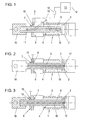
- Fig. 1 shows a partially sectioned shown pressure medium cylinder including parts of the measuring and control device and Fig. 2 and 3 show further exemplary embodiments of pressure medium cylinders according to the invention.
- the pressure medium cylinder 1 has an in in all illustrated embodiment variants sealed in the axial direction out of the cylinder 2, connected to the piston 3 and moving piston rod 4, which magnetized an elongated, differently Zones (symbolized only in FIG. 1 by the lines 5) has indicator element 6.
- This indicator element 6 or the differently magnetized zones are identified by an im Area of the lead-out 7 of the piston rod 4 in a bore 8 in the cylinder cover 9 (Figs. 1 and 2) or in a separately on the cylinder cover 9, e.g. in the form of a ring element, attached receiving element 18 (FIG. 3) arranged sensor device 10 for determination the piston position or the piston rod position can be scanned.
- FIG Line connection 11 to a processing unit 12 (for example ASIC) and to one Control unit 13 is drawn, which then via an only schematically indicated output 14 reports the respective piston or rod position in a manner not of further interest here or forwards corresponding commands.
- a processing unit 12 for example ASIC
- Control unit 13 is drawn, which then via an only schematically indicated output 14 reports the respective piston or rod position in a manner not of further interest here or forwards corresponding commands.
- the indicator element 6 is in one in the illustrated embodiments Piston rod 4 arranged essentially centrally arranged axial bore 15, wherein this axial bore 15 in the case of FIG. 1 as from the side of the rod head 16 and in 2 is designed as a blind hole extending from the side of the piston 3, which is closed on the open side by means of a fixing or sealing element 17. 3, the piston rod 4 is open on both sides, in the Inner bore 15 the correspondingly fixed and, if necessary, sealed indicator element 6 supporting tube formed, which on one side the piston 3 and on the other Side carries the rod head 16. There is an element 17 for sealing only on one side the bore 15 is drawn - of course, such an element could, if necessary also close the bore 15 on the rod side or the indicator element 6 completely fix and seal.
- the indicator element 6 with its spaced apart Zones of different magnetization have different known possibilities - it is only essential that these axially spaced zones make a clear determination allow the position of the piston rod 4 or at least some positions of the piston rod 4.
Landscapes
- Engineering & Computer Science (AREA)
- Physics & Mathematics (AREA)
- Fluid Mechanics (AREA)
- Mechanical Engineering (AREA)
- General Engineering & Computer Science (AREA)
- Actuator (AREA)
- Pistons, Piston Rings, And Cylinders (AREA)
- Measurement Of Length, Angles, Or The Like Using Electric Or Magnetic Means (AREA)
Abstract
Description
Claims (5)
- Druckmittelzylinder (1), mit einer in axialer Richtung abgedichtet aus dem Zylinder (2) geführten, mit dem Kolben (3) mitbewegten Kolbenstange (4), die ein längserstrecktes, unterschiedlich magnetisierte Zonen (5) aufweisendes Indikatorelement (6) trägt, das durch eine im Bereich der Herausführung (7) der Kolbenstange (4) angeordnete Sensoreinrichtung (10) zur Ermittlung der Kolbenposition abtastbar ist, dadurch gekennzeichnet, dass die Kolbenstange (4) eine im wesentlichen zentral angeordnete Axialbohrung (15) aufweist, in der das Indikatorelement (4) angeordnet ist.
- Druckmittelzylinder nach Anspruch 1, dadurch gekennzeichnet, dass die das fixierte und gegebenenfalls abgedichtete Indikatorelement (6) aufnehmende Axialbohrung (15) der Kolbenstange (4) als von der Seite des Kolbens (3) bzw. der Seite des Stangenkopfes (16) ausgehende Sacklochbohrung ausgeführt ist.
- Druckmittelzylinder nach Anspruch 1, dadurch gekennzeichnet, dass die Kolbenstange (4) als beidseitig offenes, in der Innenbohrung (15) das fixierte und abgedichtete Indikatorelement (6) tragendes Rohr ausgebildet ist, welches auf der einen Seite den Kolben (3) und auf der anderen Seite den Stangenkopf (16) trägt.
- Druckmittelzylinder nach einem der Ansprüche 1 bis 3, dadurch gekennzeichnet, dass die Sensoreinrichtung (10) in einer Bohrung (8) im Zylinderdeckel (9) nahe der Kolbenstangendurchführung (7) angeordnet ist.
- Druckmittelzylinder nach einem der Ansprüche 1 bis 3, dadurch gekennzeichnet, daß die Sensoreinrichtung (10) in einem nahe der Kolbenstangendurchführung (7) am Zylinderdeckel (9) angebrachten, separaten Aufnahmeelement (18) angeordnet ist.
Applications Claiming Priority (2)
| Application Number | Priority Date | Filing Date | Title |
|---|---|---|---|
| AT21162000 | 2000-12-20 | ||
| AT21162000 | 2000-12-20 |
Publications (2)
| Publication Number | Publication Date |
|---|---|
| EP1217221A2 true EP1217221A2 (de) | 2002-06-26 |
| EP1217221A3 EP1217221A3 (de) | 2004-03-17 |
Family
ID=3689890
Family Applications (1)
| Application Number | Title | Priority Date | Filing Date |
|---|---|---|---|
| EP01890344A Withdrawn EP1217221A3 (de) | 2000-12-20 | 2001-12-19 | Druckmittelzylinder |
Country Status (1)
| Country | Link |
|---|---|
| EP (1) | EP1217221A3 (de) |
Cited By (3)
| Publication number | Priority date | Publication date | Assignee | Title |
|---|---|---|---|---|
| US6863334B2 (en) * | 2001-06-01 | 2005-03-08 | Bayerische Motoren Werke Aktiengesellschaft | System for opening and closing a folding top or displaceable vehicle roof on a convertible vehicle |
| WO2007110095A1 (en) * | 2006-03-28 | 2007-10-04 | Norgren Gmbh | Displacement sensor for a rod |
| EP3293402A1 (de) * | 2016-09-07 | 2018-03-14 | ELGO-Electronic GmbH & Co. KG | Kolben-zylindervorrichtung und verwendung einer solchen |
Citations (2)
| Publication number | Priority date | Publication date | Assignee | Title |
|---|---|---|---|---|
| WO1994007037A1 (en) | 1992-09-23 | 1994-03-31 | Ab Rexroth Mecman | Positioning device for fluid cylinder |
| EP0695879A1 (de) | 1994-08-02 | 1996-02-07 | Festo KG | Arbeitszylinder |
Family Cites Families (4)
| Publication number | Priority date | Publication date | Assignee | Title |
|---|---|---|---|---|
| DE3324584A1 (de) * | 1982-07-07 | 1984-01-12 | Linde Ag, 6200 Wiesbaden | Einrichtung zum feststellen einer relativen verschiebelage |
| US4717874A (en) * | 1984-02-10 | 1988-01-05 | Kabushiki Kaisha Sg | Reluctance type linear position detection device |
| JPS635201A (ja) * | 1986-06-25 | 1988-01-11 | Denki Kagaku Kogyo Kk | 直線変位検出装置 |
| DE3734547A1 (de) * | 1987-10-13 | 1989-05-03 | Festo Kg | Kolben-zylinder-aggregat |
-
2001
- 2001-12-19 EP EP01890344A patent/EP1217221A3/de not_active Withdrawn
Patent Citations (2)
| Publication number | Priority date | Publication date | Assignee | Title |
|---|---|---|---|---|
| WO1994007037A1 (en) | 1992-09-23 | 1994-03-31 | Ab Rexroth Mecman | Positioning device for fluid cylinder |
| EP0695879A1 (de) | 1994-08-02 | 1996-02-07 | Festo KG | Arbeitszylinder |
Cited By (5)
| Publication number | Priority date | Publication date | Assignee | Title |
|---|---|---|---|---|
| US6863334B2 (en) * | 2001-06-01 | 2005-03-08 | Bayerische Motoren Werke Aktiengesellschaft | System for opening and closing a folding top or displaceable vehicle roof on a convertible vehicle |
| WO2007110095A1 (en) * | 2006-03-28 | 2007-10-04 | Norgren Gmbh | Displacement sensor for a rod |
| CN101427106B (zh) * | 2006-03-28 | 2012-02-22 | 诺格伦有限责任公司 | 用于连杆的位移传感器 |
| US8237430B2 (en) | 2006-03-28 | 2012-08-07 | Norgren Gmbh | Displacement sensor for a rod |
| EP3293402A1 (de) * | 2016-09-07 | 2018-03-14 | ELGO-Electronic GmbH & Co. KG | Kolben-zylindervorrichtung und verwendung einer solchen |
Also Published As
| Publication number | Publication date |
|---|---|
| EP1217221A3 (de) | 2004-03-17 |
Similar Documents
| Publication | Publication Date | Title |
|---|---|---|
| DE102015102233B4 (de) | Positionssensor und damit erstellte Messanordnung | |
| EP1489385B1 (de) | Vorrichtung zur Sensierung der axialen Stellung eines ersten Bauteils, das relativ zu einem zweiten Bauteil bewegbar ist | |
| EP3840968B1 (de) | Wankstabilisator | |
| DE3319522C2 (de) | Druckmittelbetätigte Kolben-Zylinder-Einheit | |
| DE102016121671B3 (de) | Positionssensor und Stellgerät mit Positionssensor | |
| DE102009041159B4 (de) | Wegsensoreinheit und Anordnung mit der Wegsensoreinheit | |
| CH688419A5 (de) | Sicherheitsventil fuer einen Dampfdruckkochtopf. | |
| DE19939497A1 (de) | Antrieb eines Stellventils mit Sensiereinheit zur Ventilpositionserfassung | |
| EP2394063A1 (de) | Kolben-zylinderanordnung mit integrierter messeinrichtung | |
| DE102006049724A1 (de) | Ventilanordnung mit Positionssensor | |
| WO2009080633A1 (de) | Strömungssensor für fluide medien | |
| DE10200609A1 (de) | Elektrisch unterstützte Hilfskraftlenkung für Kraftfahrzeuge | |
| DE202018103775U1 (de) | Leistungsmessanordnung | |
| WO2000073756A1 (de) | Sensor, insbesondere magnetostriktiver oder magnetoelastischer sensor | |
| DE102006045827A1 (de) | Axialverschiebbares Bauteil insbesondere in einem Kraftfahrzeugmotor oder -getriebe | |
| EP3611088B1 (de) | Tretlager und fahrrad mit einem solchen tretlager | |
| DE3634730A1 (de) | Arbeitszylinder, insbesondere pneumatikzylinder fuer komponenten von handlingautomaten | |
| EP1217221A2 (de) | Druckmittelzylinder | |
| EP1253329B1 (de) | Druckmittelzylinder mit einer Verdrehsicherung | |
| DE102005060674C5 (de) | Positionssensor in Stabbauweise sowie Verfahren zum Austausch | |
| EP1070856B1 (de) | Vorrichtung zur Erfassung der Lage eines Kolbens | |
| DE10307569B4 (de) | Vorrichtung zur Wegbestimmung eines Kolbens in einem Zylinder | |
| DE19846418A1 (de) | Hydraulikventil mit Sensor | |
| DE102004060920B4 (de) | Stabmagnet für Meßeinrichtung, Meßeinrichtung | |
| EP1491771A1 (de) | Einrichtung zur Ermittlung der aktuellen Stellung eines Antriebsgliedes |
Legal Events
| Date | Code | Title | Description |
|---|---|---|---|
| PUAI | Public reference made under article 153(3) epc to a published international application that has entered the european phase |
Free format text: ORIGINAL CODE: 0009012 |
|
| AK | Designated contracting states |
Kind code of ref document: A2 Designated state(s): AT BE CH CY DE DK ES FI FR GB GR IE IT LI LU MC NL PT SE TR |
|
| AX | Request for extension of the european patent |
Free format text: AL;LT;LV;MK;RO;SI |
|
| PUAL | Search report despatched |
Free format text: ORIGINAL CODE: 0009013 |
|
| AK | Designated contracting states |
Kind code of ref document: A3 Designated state(s): AT BE CH CY DE DK ES FI FR GB GR IE IT LI LU MC NL PT SE TR |
|
| AX | Request for extension of the european patent |
Extension state: AL LT LV MK RO SI |
|
| 17P | Request for examination filed |
Effective date: 20040408 |
|
| 17Q | First examination report despatched |
Effective date: 20040805 |
|
| AKX | Designation fees paid |
Designated state(s): DE FR SE |
|
| STAA | Information on the status of an ep patent application or granted ep patent |
Free format text: STATUS: THE APPLICATION IS DEEMED TO BE WITHDRAWN |
|
| 18D | Application deemed to be withdrawn |
Effective date: 20041216 |