EP1217285B1 - Verbinder für Kleintierkäfigsysteme - Google Patents
Verbinder für Kleintierkäfigsysteme Download PDFInfo
- Publication number
- EP1217285B1 EP1217285B1 EP01129206A EP01129206A EP1217285B1 EP 1217285 B1 EP1217285 B1 EP 1217285B1 EP 01129206 A EP01129206 A EP 01129206A EP 01129206 A EP01129206 A EP 01129206A EP 1217285 B1 EP1217285 B1 EP 1217285B1
- Authority
- EP
- European Patent Office
- Prior art keywords
- inner ring
- connector
- ring
- seats
- tubular members
- Prior art date
- Legal status (The legal status is an assumption and is not a legal conclusion. Google has not performed a legal analysis and makes no representation as to the accuracy of the status listed.)
- Expired - Lifetime
Links
Images


Classifications
-
- F—MECHANICAL ENGINEERING; LIGHTING; HEATING; WEAPONS; BLASTING
- F16—ENGINEERING ELEMENTS AND UNITS; GENERAL MEASURES FOR PRODUCING AND MAINTAINING EFFECTIVE FUNCTIONING OF MACHINES OR INSTALLATIONS; THERMAL INSULATION IN GENERAL
- F16L—PIPES; JOINTS OR FITTINGS FOR PIPES; SUPPORTS FOR PIPES, CABLES OR PROTECTIVE TUBING; MEANS FOR THERMAL INSULATION IN GENERAL
- F16L37/00—Couplings of the quick-acting type
- F16L37/08—Couplings of the quick-acting type in which the connection between abutting or axially overlapping ends is maintained by locking members
- F16L37/12—Couplings of the quick-acting type in which the connection between abutting or axially overlapping ends is maintained by locking members using hooks, pawls, or other movable or insertable locking members
- F16L37/18—Joints tightened by eccentrics or rotatable cams
-
- F—MECHANICAL ENGINEERING; LIGHTING; HEATING; WEAPONS; BLASTING
- F16—ENGINEERING ELEMENTS AND UNITS; GENERAL MEASURES FOR PRODUCING AND MAINTAINING EFFECTIVE FUNCTIONING OF MACHINES OR INSTALLATIONS; THERMAL INSULATION IN GENERAL
- F16L—PIPES; JOINTS OR FITTINGS FOR PIPES; SUPPORTS FOR PIPES, CABLES OR PROTECTIVE TUBING; MEANS FOR THERMAL INSULATION IN GENERAL
- F16L37/00—Couplings of the quick-acting type
- F16L37/08—Couplings of the quick-acting type in which the connection between abutting or axially overlapping ends is maintained by locking members
- F16L37/10—Couplings of the quick-acting type in which the connection between abutting or axially overlapping ends is maintained by locking members using a rotary external sleeve or ring on one part
- F16L37/101—Couplings of the quick-acting type in which the connection between abutting or axially overlapping ends is maintained by locking members using a rotary external sleeve or ring on one part in which the coupling is coaxial with the pipe
-
- A—HUMAN NECESSITIES
- A01—AGRICULTURE; FORESTRY; ANIMAL HUSBANDRY; HUNTING; TRAPPING; FISHING
- A01K—ANIMAL HUSBANDRY; AVICULTURE; APICULTURE; PISCICULTURE; FISHING; REARING OR BREEDING ANIMALS, NOT OTHERWISE PROVIDED FOR; NEW BREEDS OF ANIMALS
- A01K15/00—Devices for taming animals, e.g. nose-rings or hobbles; Devices for overturning animals in general; Training or exercising equipment; Covering boxes
- A01K15/02—Training or exercising equipment, e.g. mazes or labyrinths for animals ; Electric shock devices; Toys specially adapted for animals
- A01K15/025—Toys specially adapted for animals
Definitions
- This invention relates to cage systems for small animals and more particularly relates to connectors used to join various parts of the system together.
- a number of small animal cage systems are presently available to house such animals as hamsters, ferrets, gerbils etc.
- One of the best known and most popular of these systems is sold under the trademark HABITRAIL by Rolf C. Hagen, Inc. of Montreal, Canada and its United States subsidiary Rolf C. Hagen (USA) Corp. of Mansfield, Massachusetts.
- That system includes a large number of different items including cages, plastic enclosures such as living quarters, play stations, exercise and eating compartments, towers etc that are joined together by tubes of different length and connectors that couple the tubes and various items of the system with one another.
- Competitive systems have somewhat similar arrangements.
- DE-A-43 27 461 discloses a device for securing the plug-in position between a threaded shank having a cylinder core, and a sheath part with a corresponding cylinder bore.
- a connector is described for joining tubular members comprising inner and outer concentric rings, an interconnection between the rings and camming surfaces on the inner surface of the outer ring and the outer surface of the inner ring.
- One object of the present invention is to provide a connector that is easy to use and operates effectively to join the various parts of the system together.
- Another more specific object of the invention is to provide a connector that does not require a specific circumferential orientation between the connector and either of the parts of the system to be joined by the connector.
- Another object of the present invention is to provide a connector that creates a strong and secure connection between the two parts of the system that are joined together by it.
- an object is to provide a connector that is easy to handle and has a good gripping surface so that it may be attached to and removed from any item to which it is joined.
- an object is to provide a connector that accommodates a wide range of dimensional tolerances in the objects to which it is to be connected.
- the connector of the present invention includes an outer ring and an inner ring that are circumferentially movable with respect to one another.
- the inner ring is discontinuous, composed of two or more sections with their adjacent ends closely spaced to form a substantially continuous ring.
- the discontinuity of the inner ring enables the effective diameter of the inner ring to be easily reduced so as to firmly grip a tube or other item that is to be engaged by the connector and greatly reduces manufacturing tool costs.
- the inner ring has a pair of parallel grooves on its inner surface that are designed to receive the ends of the members that are to be joined together by the connector.
- the ends of the members to be joined are essentially round so that they may fit within the inner rings and seat in the grooves.
- the connector and the mating ends of members to be joined by the connector may take many different forms that allow the connector to grip the members when the connector is in the locked position.
- the outer surface of the inner ring and the inner surface of the outer ring carry a plurality of camming surfaces that are spaced apart a circumferential distance that is greater than that of the surfaces so that the rings can be moved relative to one another between a first position (unlocked) wherein the surfaces are disengaged in which case no compressive forces are applied to the inner ring by the outer ring, and a second position (locked) wherein they are engaged causing the outer ring to compress the inner ring to reduce its effective diameter so that it firmly grips the members.
- the inner ring In the first position the inner ring is sized to receive the ends of the members that are to be joined together while in the second position the connector is locked onto the members so that they can not be pulled apart or otherwise separate from one another.
- camming surfaces are provided on both the inner and outer rings for each side of the connector that receives one of the members that are to be joined together.
- the camming surfaces on one side of the connector are axially aligned with the spaces between the cam surfaces on the other side so that the compression exerted on the inner ring by the outer ring when the camming surfaces are engaged is spread evenly about the connector.
- the inner ring is co-injected or insert molded with a gasket made of a yieldable material so as to more firmly engage the ends of the members coupled by the connector.
- FIG. 1 a typical application of the present invention is shown wherein a pair of tubular members 10 and 12 are joined together by a connector 14. While tubular members 10 and 12 are straight and curved tube segments respectively, it is to be , understood that the connector of the present invention may be used to join any two members together that have a tubular collar-like end that preferably has a bead on its outer surface at its free edge.
- the tubular member 12 is shown to have a bead 16 on its outer surface 18 adjacent its edge 20.
- Each end of each of the tubular members 10 and 12 has such a bead.
- the end 22 of the tubular member 14 serves as a collar that may be inserted into the connector 14 as is described in detail below.
- the bead may be approximately 3,2 mm (1/8 inch) wide and 1,6 mm (1/16 inch) high, and preferably it is beveled toward the end of the tube. It is to be understood however that the bead may be of different dimensions as dictated by the size and other physical characteristics of the connector 14.
- the tubes 10 and 12 are only representative of any type of member that is connected as part of the cage assembly with other parts thereof, such as living quarters, play stations, exercise or eating compartments, towers etc.
- the number of different members that may be connected in such assemblies is almost limitless, and the connector of this invention may be used to connect any member to another so long as the ends of the members have a shape complimentary to the connector.
- the members joined together by the connector are sometimes called tubes, but it is to be understood that when "tube” is used it includes by definition any other part of the assembly that is provided with a collar-like fitting to register with the connector.
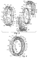
- the tube connector 14 is shown in detail in FIGS. 2-11.
- the connector 14 includes outer and inner rings 40 and 42 that are circumferentially movable with respect to one another.
- the outer ring 40 typically may be made of a variety of materials such as styrene, and may be injection molded by techniques well known in the art.
- the inner ring in the embodiment shown that may be made of polypropylene or other similar material is preferably discontinuous, that is, it is composed of two or more arcuate components 42A and 42B (two segments are shown in the illustrated embodiment) that together comprise an essentially continuous ring. Each segment is preferably co-injected or insert molded with an inner portion 46 that is relatively flexible and typically made of an elastomeric material.
- the inner portion 46 serves as a gasket identified in the following description and shown in the drawing at 106 to firmly engage the two collar-like fittings on the member to be joined by the connector 14.
- the two segments 42A and 42B in the embodiment illustrated when inserted within the outer ring 40, form a continuation of one another to define an essentially continuous inner ring 42 within the outer ring 40.
- the outer ring 40 is shown in detail particularly in the cross-sectional views of FIGS. 7, 8, 9 and 11 and in FIG. 3.
- the outer ring 40 has outer and inner surfaces 48 and 50, and the outer surface carries a number of ribs 52 that facilitate gripping of the outer ring. It should, of course, be appreciated that while ribs are shown formed in the outer surface 48 of the outer ring for that purpose, the surface can be otherwise configured such as with nirls, bumps, etc. for accomplishing the same purpose.
- the inner surface 50 of the outer ring 40 carries a radially, inwardly extending rib 54 about the inner circumference of the outer ring 40 essentially midway between the outer edges 56.
- the rib 54 in the embodiment shown is continuous.
- the rib 54 serves to stiffen the outer ring and also provides a track on which the inner ring 42 is mounted as is described in more detail below. Also disposed on the inner surface 50 of the outer ring 40 on each side of the rib 54 are inwardly extending protrusions 60 that bear upon the outer surface of the inner ring so as to compress the inner ring against the tubular members coupled together by the tube connector 14 of this invention. That action is described in substantial detail below.
- the protrusions 60 are shown in FIGS. 3, 5 and 6 to be equidistantly spaced about the inner circumference of outer ring 40, with the protrusions on one side of the rib 54 being aligned with the space between adjacent protrusions on the other side of the rib.
- the circumferential ends of the protrusions 60 are defined by inclined ramps 62.
- the gaps between adjacent protrusions 60 ate identified at 64.
- the circumferential length of the protrusions 60 is slightly less than the circumferential length of the gaps 64.
- the protrusions 60 on each side of the rib 54 are circumferentially displaced from one another so that the gaps 64 on one side of the rib 54 are aligned with the protrusions 60 on the other side thereof.
- the inner ring 42 has outer and inner surfaces 70 and 72, and the outer surface 70 has a pair of radially outwardly extending beads 74 that between them define a recess 76 that receives the rib 54 on the inner surface of the outer ring 40.
- the recess 76 is equidistantly spaced from the edges 78 of the inner ring.
- the outer surface 70 of the inner ring carries a plurality of cams 80 and 82 that are spaced apart as suggested at 84 (see FIG. 3).
- the cams 80 in the embodiment shown, are in the form of straight ribs that have smooth outer surfaces 86 and ramp-like ends 88.
- the cams 82 have notches 83 on their upper surface 90, and their ends are ramped as suggested at 92.
- the cams 82 are wider than the cams 80 so that their outer edges extend beyond the edges of the remaining portions of the inner ring.
- the notches 90 in the embodiment shown, are, therefore, visible beyond the edges 56 of the outer ring.
- the radial height of the cams 80 and 82 are essentially the same.
- the cams 80 and 82 are alternately provided on the outer surface 70 of the inner ring on each side of the recess 76 and separated by the spaces 84, and the cams are each circumferentially aligned with a space 84 on the opposite side of the recess.
- the cams 80 and 82 cooperate with the protrusions 60 on the inner surface of the outer ring so as to apply compressive forces to the inner ring causing the inner ring, in turn, firmly to engage the tubes joined by the connector.
- the inner surface 72 of the inner ring 42 in the embodiment shown carries radially inwardly extending shoulders 100 disposed inwardly of the edges 78 and spaced from a central radially inwardly extending fin 102 disposed along the approximate center line of the inner surface 72 (see FIGS. 2A, 7, 8 and 9).
- the shoulders 100 and fin 102 define two spaced apart seats 104 into which the gasket 106 is co-injected or insert molded.
- the gasket 106 is made of a yieldable material such as an elastomer, when pressed against a surface such as a bead on the collar-like coupling on the tubes, the gasket will firmly grip on it.
- the gasket 106 of the inner ring 42 is shown separately in FIG. 3 before it is co-injected or insert molded with the ring.
- the gasket has a central circumferential slot 107 through which the fin 102 extends in the finished product (also see FIGS. 2A and 7-9).
- the gasket segments shown in FIG. 3 have small feet 107a at each end that merge with the ends of the segments of the inner ring to firmly anchor the two parts 42a and 42b together and may also form a cushion between the ends of the parts of the inner ring when assembled in the outer ring 40.
- the inner surface 108 of the gasket is shown in FIGS. 3 and 6-9 to provide inclined surfaces for engaging the couplings and more particularly the ends of the tubes when in use to couple segments of the assembly together.
- the outer ring 40 is rotatable with respect to the inner ring while the inner ring remains in place connected to the outer ring by virtue of the registration of the rib 54 on the outer ring with the recess 76 on the outer surface of the inner ring 42.
- the outer ring 40 is disposed on the inner ring in a circumferential position such that protrusions 60 on the inner surface of the outer ring on each side of the rib 54 are out of registration with the cams 80 and 82 on the outer surface of the inner ring, and rather are disposed opposite the spaces 84 between the cams as shown in FIG.
- the outer ring does not exert any compressive forces on the inner ring except as those that may be generated in reaction to an outward pressure exerted on the inner surface of the inner ring by the tubes to be coupled together by the connector 14. That force, if any, however does not impede the rotation of the outer ring with respect to the inner ring so that the protrusions 60 may be caused to ride up on the cams and cause a compressive force to be exerted on the inner ring so as to essentially contract its diameter.
- the connector is shown in the operative position.
- protrusions 60 engage the cams 80 and 82 so as to exert radially inwardly directed pressure on the inner ring 42 so as to cause the gasket 106 to tighten on the collar-like couplings on the ends of the tubes. It should be appreciated that the protrusions and cams on both sides of the connector 14 act together to either compress or release the inner ring.
- a number of dimples 110 are formed along the edges 56 of the outer ring on the outer surface 48 thereof. Those dimples 110 are circumferentially aligned with the protrusions 60 on the inner surface of the outer ring. The dimples 110 cooperate with the similar dimples 90 on the outer surface of the cams 82 on inner ring 42 so as to provide a visual and tactile signal that the protrusions are aligned with, and engaging the cams 82.
- the user has an indication when the inner ring is being compressed by the outer ring so as to lock the tubes together.
- the dimples 110 and 90 are misaligned, the operator then knows that the compressive load has been relieved on the inner ring and that the tubes may be disconnected from the connector.
- FIGS. 12 and 13 illustrate one of the many advantages of the present invention.
- the connector enables the two components to be joined together in any angular relationship.
- the tube 120 extends upwardly one to the side of the compartment 122 as shown in FIG. 13. If the weight of the tube for any reason is too much for the connector 14 to handle, the connector will act as a clutch and allow the tube 120 to slip slowly about the axis 124 of the coupling without separating from either the tube or compartment. The slippage will occur on the side 14A of the connector 14 that engages the coupling 126 on the end of the tube, and not on the other side 14B of the connector that engages the coupling 128 on the compartment 122.
- the inner ring has been described as being discontinuous and in the embodiment shown is made up of two segments, it will be appreciated that the inner ring may be divided into more than two segments or the inner ring may be continuous without any breaks therein depending upon the flexibility and compressibility of the material from which the inner ring is made. Therefore, variations as to the number of ring segments that are employed are within the scope of the present invention. It will also be appreciated that while in the illustrated embodiment, the inner ring is made by co-injection or insert molding and the gaskets are made of a different material than the remaining portion of the inner ring, the inner ring may be made from a single material as long as it is capable of compressing (contracting in diameter) in response to forces being applied to it by the outer ring.
- the particular arrangement for maintaining the relationship between the inner and out rings as described above and shown in the drawing may take other configurations.
- the recess 102 on the inner ring 42 and the rib 54 on the outer ring may be reversed to accomplish the same results.
- Other cross sections may be used as well to accomplish the same purpose.
- the materials used in the manufacture of the inner and outer rings while styrene has proved advantageous for the outer ring 40 and polypropylene for the inner ring 42, the scope of the invention is not limited to those particular materials, nor is the material for the gasket a limiting feature of this invention.
- the tubes are made of a polished material and the elastomeric gasket material is smooth as well, when the connector is locked onto the tubes the best gripping action is achieved between the connector and the tubes.
- the smooth surfaces provide the greatest surface to surface contact and the frictional gripping between the two is maximized.
- the mating configurations of the inner ring 42 and the tube may include a recess on the tube and ribs on the inner surface of the inner ring that mate with one another. Other complimentary configurations may be used as well.
- the bead is shown to have a slightly inclined surface with the lead in edge of the bead being beveled to allow the tube end to be inserted into the connector.
Landscapes
- Engineering & Computer Science (AREA)
- General Engineering & Computer Science (AREA)
- Mechanical Engineering (AREA)
- Quick-Acting Or Multi-Walled Pipe Joints (AREA)
- Housing For Livestock And Birds (AREA)
- Flanged Joints, Insulating Joints, And Other Joints (AREA)
- Lining Or Joining Of Plastics Or The Like (AREA)
Claims (9)
- Verbinder (14) zur Verbindung von rohrförmigen Teilen (10, 12), welche innere und äußere konzentrische Ringe (42, 40) aufweisen, die sich in Umfangsrichtung gegeneinander bewegen, mit einer Verbindung zwischen den Ringen, um den inneren Ring innerhalb des äußeren Rings zu halten, und Mitnehmerflächen (80, 82) auf der inneren Oberfläche (50) des äußeren Rings (40) und der äußeren Oberfläche (70) des inneren Rings (42), um den inneren Ring zusammenzupressen, um benachbarte Enden (22) eines Paars von rohrförmigen Teilen zu erfassen, wenn die Mitnehmerflächen miteinander ausgerichtet sind und um die Kompression auf dem inneren Ring freizugeben, wenn die Mitnehmerflächen nicht mehr zueinander ausgerichtet sind, dadurch gekennzeichnet, dass der innere Ring (42) eine Greifoberfläche aus elastomeren Material aufweist.
- Verbinder nach Anspruch 1, bei dem der innere Ring (42) eine Diskontinuität aufweist, um die Kontraktion des inneren Rings in Umfangsrichtung zu erleichtern, wenn er zusammengepresst wird.
- Verbinder nach Anspruch 1 oder 2, bei dem der innere Ring (42) einen Sitz zur Erfassung der Enden (22) eines Paars von ringförmigen Teilen (10, 12) aufweist, die endseitig über den Verbinder miteinander verbunden werden sollen.
- Verbinder nach Anspruch 1, 2 oder 3, bei dem die innere Oberfläche (72) des inneren Rings (42) ein Paar von Sitzen (104) aufweist, von denen jeder ein Ende (22) eines der zu verbindenden rohrförmigen Teilen (10, 12) erfasst.
- Verbinder nach Anspruch 4, bei dem separate Mitnehmerflächen (80, 82) auf den inneren und äußeren Ringen (42, 40) in Wirkverbindung mit jedem der Sitze (104) der inneren Oberfläche (72) des inneren Rings (42) ausgerichtet ist, um die Sitze getrennt gegen die Enden (22) der rohrförmigen Teile (10, 12), die die Sitze erfassen, zu komprimieren.
- Verbinder nach Anspruch 5, bei dem eine Mehrzahl von Mitnehmerflächen (80, 82) auf der äußeren Oberfläche (70) des inneren Rings (42) und eine Mehrzahl von Mitnehmerflächen auf den inneren Oberflächen (50) des äußeren Rings (40) vorgesehen sind, und wobei der äußere Ring in Bezug auf den inneren Ring in beliebiger Richtung gedreht werden kann, um die Mitnehmerflächen in Eingriff oder aus dem Eingriff zueinander zu bewegen.
- Verbinder nach Anspruch 5 oder 6, bei dem die Mitnehmerflächen (80, 82) einem der Sitze (104) operativ zugeordnet sind, in Umfangsrichtung in Bezug auf die Mitnehmerflächen versetzbar sind, die operativ dem anderen der Sitze (104) zugeordnet sind.
- Verbinder nach Anspruch 1 und 2, bei dem eine Umfangsrippe (102) die innere Oberfläche des inneren Rings (42) in ein Paar von umlaufenden Sitzen (104) teilt, die jeweils an einer Seite der Rippe angeordnet sind, wobei jeder Sitz ein Ende (22) eines der rohrförmigen Teile (10, 12) aufnimmt,
einem sich radial nach innen gerichteten Flansch (100) an jeder Seite des inneren Rings, der zusammen mit der Rippe das Paar von Sitzen (104) bildet,
wobei die Mitnehmerflächen (80, 82) des inneren Rings eine Mehrzahl von erhobenen Mitnehmern an der Außenseite (70) des inneren Rings aufweisen, die separat radial mit einem der anderen Sitze auf der Innenseite (72) des inneren Rings ausgerichtet sind,
wobei der äußere Ring (40), der den inneren Ring verbindet und umgibt, und innere und äußere Seiten mit radial nach innen gerichteten Vorsprüngen auf der Innenseite aufweist, um selektiv die Mitnehmer der äußeren Seiten des inneren Rings zu erfassen, um den inneren Ring gegen die Enden der rohrförmigen Teile zusammenzupressen, um ihre Enden in fester Beziehung zueinander zu halten,
wobei der äußere Ring auf dem inneren Ring drehbar ist, um die Vorsprünge und Mitnehmer selektiv zu erfassen und zu trennen. - Verbinder nach Anspruch 8, bei dem die äußere Seite des äußeren Rings Greifer (52, 110) aufweist, um die Drehung des äußeren Rings auf dem inneren Ring zu unterstützen.
Applications Claiming Priority (2)
| Application Number | Priority Date | Filing Date | Title |
|---|---|---|---|
| US09/745,699 US6494502B1 (en) | 2000-12-21 | 2000-12-21 | Connector for small animal cage systems |
| US745699 | 2000-12-21 |
Publications (2)
| Publication Number | Publication Date |
|---|---|
| EP1217285A1 EP1217285A1 (de) | 2002-06-26 |
| EP1217285B1 true EP1217285B1 (de) | 2005-02-09 |
Family
ID=24997856
Family Applications (1)
| Application Number | Title | Priority Date | Filing Date |
|---|---|---|---|
| EP01129206A Expired - Lifetime EP1217285B1 (de) | 2000-12-21 | 2001-12-07 | Verbinder für Kleintierkäfigsysteme |
Country Status (5)
| Country | Link |
|---|---|
| US (1) | US6494502B1 (de) |
| EP (1) | EP1217285B1 (de) |
| JP (1) | JP3602498B2 (de) |
| AT (1) | ATE289034T1 (de) |
| DE (1) | DE60108837D1 (de) |
Cited By (1)
| Publication number | Priority date | Publication date | Assignee | Title |
|---|---|---|---|---|
| US9851033B2 (en) | 2012-02-25 | 2017-12-26 | Arnold Jäger Holding GmbH | Component connector for connecting cylindrical components |
Families Citing this family (21)
| Publication number | Priority date | Publication date | Assignee | Title |
|---|---|---|---|---|
| US20030129043A1 (en) * | 2000-03-09 | 2003-07-10 | Clare James Carter | Portable irrigation pipe installation system |
| US20060152004A1 (en) * | 2005-01-12 | 2006-07-13 | Luo Yih W | Pipe connecting structure |
| US7624705B2 (en) * | 2007-04-30 | 2009-12-01 | Rolf C. Hagen, Inc. | Small animal habitat |
| USD605734S1 (en) * | 2008-12-03 | 2009-12-08 | Victaulic Company | Rigid pipe coupling |
| USD600784S1 (en) * | 2008-12-04 | 2009-09-22 | Victaulic Company | Flexible pipe coupling |
| USD605735S1 (en) * | 2008-12-13 | 2009-12-08 | Victaulic Company | Ribbed pipe coupling |
| USD602127S1 (en) * | 2009-01-27 | 2009-10-13 | Victaulic Company | Flexible ribbed pipe coupling |
| USD616072S1 (en) * | 2009-07-09 | 2010-05-18 | Victaulic Company | Rigid pipe coupling |
| US20120068459A1 (en) * | 2010-09-16 | 2012-03-22 | Mao-Nan Cheng | Fitting ring |
| US20120155953A1 (en) * | 2010-12-21 | 2012-06-21 | Caterpillar Inc. | Seal ring stabilization system and associated pin joint assembly |
| GB201209696D0 (en) * | 2012-05-31 | 2012-07-18 | Teconnex Ltd | Clamping means and method of use thereof |
| USD685886S1 (en) | 2012-10-01 | 2013-07-09 | Victaulic Company | Pipe coupling segment |
| USD685884S1 (en) | 2012-10-01 | 2013-07-09 | Victaulic Company | Pipe coupling segment |
| USD685885S1 (en) | 2012-10-01 | 2013-07-09 | Victaulic Company | Pipe coupling segment |
| USD685887S1 (en) | 2012-10-01 | 2013-07-09 | Victaulic Company | Pipe coupling segment |
| USD685889S1 (en) | 2012-10-02 | 2013-07-09 | Victaulic Company | Pipe coupling segment |
| USD685888S1 (en) | 2012-10-02 | 2013-07-09 | Victaulic Company | Pipe coupling segment |
| US9664321B2 (en) | 2013-05-20 | 2017-05-30 | Steere Enterprises, Inc. | Clean air duct and retaining clip and assembly thereof |
| US10859194B2 (en) | 2013-05-20 | 2020-12-08 | Steere Enterprises, Inc. | Clean air duct and retaining clip and assembly thereof |
| WO2018087754A1 (en) * | 2016-11-10 | 2018-05-17 | Keter Plastic Ltd. | Containers and system for assembly thereof |
| US11486522B2 (en) * | 2020-08-18 | 2022-11-01 | Kennedy Valve Company | Pipe connector |
Family Cites Families (12)
| Publication number | Priority date | Publication date | Assignee | Title |
|---|---|---|---|---|
| US1477440A (en) | 1920-09-11 | 1923-12-11 | Jr Frederick A Grier | Coupling device |
| US3742908A (en) | 1971-04-30 | 1973-07-03 | Mattel Inc | Animal habitat |
| US3859961A (en) | 1972-01-21 | 1975-01-14 | Metaframe Corp | Animal path connecting system |
| USD256956S (en) | 1977-07-11 | 1980-09-16 | Metaframe Corporation | Passageway joint for a small animal habitat or the like |
| GB8508757D0 (en) | 1985-04-03 | 1985-05-09 | Robson A R | Pipe couplings |
| US4733438A (en) * | 1987-04-02 | 1988-03-29 | Jss Scientific Corporation | Coolant hose clamp |
| DE9115401U1 (de) | 1991-12-12 | 1992-03-12 | Kandl, Michael, 7800 Freiburg | Kupplungssystem zur Kupplung von Tuben |
| CA2083451C (en) * | 1992-11-20 | 1996-09-17 | Geoffrey Philip Anthony | Universal locking connector for human breathing systems |
| DE4327461A1 (de) | 1993-04-24 | 1994-10-27 | Prym Werke William | Vorrichtung zum Sichern der Stecklage zwischen einem Kernteil und einem Hüllteil, wie zwischen einem Gewindeschaft und seiner Schraubenmutter |
| GB9620421D0 (en) * | 1996-10-01 | 1996-11-20 | Royack Ltd | Pipe coupling device |
| US6250686B1 (en) * | 1999-01-25 | 2001-06-26 | Zurn Industries, Inc. | Combination mechanical/fusion pipe fitting |
| US6102450A (en) * | 1999-06-03 | 2000-08-15 | Snap-Tite Technologies, Inc. | Coupling half and method of making same |
-
2000
- 2000-12-21 US US09/745,699 patent/US6494502B1/en not_active Expired - Fee Related
-
2001
- 2001-12-07 DE DE60108837T patent/DE60108837D1/de not_active Expired - Lifetime
- 2001-12-07 AT AT01129206T patent/ATE289034T1/de not_active IP Right Cessation
- 2001-12-07 EP EP01129206A patent/EP1217285B1/de not_active Expired - Lifetime
- 2001-12-21 JP JP2001388716A patent/JP3602498B2/ja not_active Expired - Fee Related
Cited By (1)
| Publication number | Priority date | Publication date | Assignee | Title |
|---|---|---|---|---|
| US9851033B2 (en) | 2012-02-25 | 2017-12-26 | Arnold Jäger Holding GmbH | Component connector for connecting cylindrical components |
Also Published As
| Publication number | Publication date |
|---|---|
| EP1217285A1 (de) | 2002-06-26 |
| DE60108837D1 (de) | 2005-03-17 |
| JP3602498B2 (ja) | 2004-12-15 |
| US6494502B1 (en) | 2002-12-17 |
| JP2002235888A (ja) | 2002-08-23 |
| ATE289034T1 (de) | 2005-02-15 |
Similar Documents
| Publication | Publication Date | Title |
|---|---|---|
| EP1217285B1 (de) | Verbinder für Kleintierkäfigsysteme | |
| KR100314314B1 (ko) | 2개의 유체 파이프라인을 연결하기 위한 플러그 접속식 커플링 | |
| RU2213899C2 (ru) | Соединительное устройство | |
| US5322466A (en) | Detachable connecting device for toy-construction elements | |
| US5851035A (en) | Self-locking union for pipes | |
| US6413004B1 (en) | Tubular connector | |
| EP0509015B1 (de) | Gerüstkupplung | |
| EP0225554B1 (de) | Auswechselbare Kupplungseinrichtung | |
| US4991882A (en) | Fluid-tight connector | |
| AU2011261151B2 (en) | Shear element for a coupling | |
| KR101780411B1 (ko) | 피복 강관용 이탈방지 압륜을 이용한 피복 강관의 결합 구조 | |
| GB2236567A (en) | A hose coupling | |
| US20020125971A1 (en) | Waveguide interconnection system | |
| JPH09505871A (ja) | スクイーズ・リリースクイックコネクタ | |
| JP2995174B2 (ja) | 密閉装置 | |
| CA2354341A1 (en) | Hose coupling with retainer ring | |
| US6884105B2 (en) | Connector with snap collar latching | |
| BRPI0808318A2 (pt) | "acoplamento macho conectável e separável de um acoplamento fêmea" | |
| JPH11509787A (ja) | 万能ソケットレンチ | |
| JP2003031306A (ja) | 電気コネクタ結合機構 | |
| US2831716A (en) | Releasable couplings | |
| JP2512703Y2 (ja) | 光ファイバ―ケ―ブルの内装管における端末防水プラグ | |
| CN215333821U (zh) | 一种管体连接器 | |
| JPS63266213A (ja) | 着脱自在な結合装置 | |
| TWM566082U (zh) | Universal needle guard |
Legal Events
| Date | Code | Title | Description |
|---|---|---|---|
| PUAI | Public reference made under article 153(3) epc to a published international application that has entered the european phase |
Free format text: ORIGINAL CODE: 0009012 |
|
| AK | Designated contracting states |
Kind code of ref document: A1 Designated state(s): AT BE CH CY DE DK ES FI FR GB GR IE IT LI LU MC NL PT SE TR |
|
| AX | Request for extension of the european patent |
Free format text: AL;LT;LV;MK;RO;SI |
|
| 17P | Request for examination filed |
Effective date: 20021218 |
|
| AKX | Designation fees paid |
Designated state(s): AT BE CH CY DE DK ES FI FR GB GR IE IT LI LU MC NL PT SE TR |
|
| 17Q | First examination report despatched |
Effective date: 20030711 |
|
| GRAP | Despatch of communication of intention to grant a patent |
Free format text: ORIGINAL CODE: EPIDOSNIGR1 |
|
| GRAS | Grant fee paid |
Free format text: ORIGINAL CODE: EPIDOSNIGR3 |
|
| GRAA | (expected) grant |
Free format text: ORIGINAL CODE: 0009210 |
|
| AK | Designated contracting states |
Kind code of ref document: B1 Designated state(s): AT BE CH CY DE DK ES FI FR GB GR IE IT LI LU MC NL PT SE TR |
|
| PG25 | Lapsed in a contracting state [announced via postgrant information from national office to epo] |
Ref country code: IT Free format text: LAPSE BECAUSE OF FAILURE TO SUBMIT A TRANSLATION OF THE DESCRIPTION OR TO PAY THE FEE WITHIN THE PRE;WARNING: LAPSES OF ITALIAN PATENTS WITH EFFECTIVE DATE BEFORE 2007 MAY HAVE OCCURRED AT ANY TIME BEFORE 2007. THE CORRECT EFFECTIVE DATE MAY BE DIFFERENT FROM THE ONE RECORDED.SCRIBED TIME-LIMIT Effective date: 20050209 Ref country code: AT Free format text: LAPSE BECAUSE OF FAILURE TO SUBMIT A TRANSLATION OF THE DESCRIPTION OR TO PAY THE FEE WITHIN THE PRESCRIBED TIME-LIMIT Effective date: 20050209 Ref country code: FR Free format text: LAPSE BECAUSE OF NON-PAYMENT OF DUE FEES Effective date: 20050209 Ref country code: FI Free format text: LAPSE BECAUSE OF FAILURE TO SUBMIT A TRANSLATION OF THE DESCRIPTION OR TO PAY THE FEE WITHIN THE PRESCRIBED TIME-LIMIT Effective date: 20050209 Ref country code: BE Free format text: LAPSE BECAUSE OF FAILURE TO SUBMIT A TRANSLATION OF THE DESCRIPTION OR TO PAY THE FEE WITHIN THE PRESCRIBED TIME-LIMIT Effective date: 20050209 Ref country code: CH Free format text: LAPSE BECAUSE OF FAILURE TO SUBMIT A TRANSLATION OF THE DESCRIPTION OR TO PAY THE FEE WITHIN THE PRESCRIBED TIME-LIMIT Effective date: 20050209 Ref country code: ES Free format text: LAPSE BECAUSE OF FAILURE TO SUBMIT A TRANSLATION OF THE DESCRIPTION OR TO PAY THE FEE WITHIN THE PRESCRIBED TIME-LIMIT Effective date: 20050209 Ref country code: TR Free format text: LAPSE BECAUSE OF FAILURE TO SUBMIT A TRANSLATION OF THE DESCRIPTION OR TO PAY THE FEE WITHIN THE PRESCRIBED TIME-LIMIT Effective date: 20050209 Ref country code: NL Free format text: LAPSE BECAUSE OF FAILURE TO SUBMIT A TRANSLATION OF THE DESCRIPTION OR TO PAY THE FEE WITHIN THE PRESCRIBED TIME-LIMIT Effective date: 20050209 Ref country code: LI Free format text: LAPSE BECAUSE OF FAILURE TO SUBMIT A TRANSLATION OF THE DESCRIPTION OR TO PAY THE FEE WITHIN THE PRESCRIBED TIME-LIMIT Effective date: 20050209 |
|
| REG | Reference to a national code |
Ref country code: GB Ref legal event code: FG4D |
|
| REG | Reference to a national code |
Ref country code: CH Ref legal event code: EP |
|
| REG | Reference to a national code |
Ref country code: IE Ref legal event code: FG4D |
|
| REF | Corresponds to: |
Ref document number: 60108837 Country of ref document: DE Date of ref document: 20050317 Kind code of ref document: P |
|
| PG25 | Lapsed in a contracting state [announced via postgrant information from national office to epo] |
Ref country code: SE Free format text: LAPSE BECAUSE OF FAILURE TO SUBMIT A TRANSLATION OF THE DESCRIPTION OR TO PAY THE FEE WITHIN THE PRESCRIBED TIME-LIMIT Effective date: 20050509 Ref country code: DK Free format text: LAPSE BECAUSE OF FAILURE TO SUBMIT A TRANSLATION OF THE DESCRIPTION OR TO PAY THE FEE WITHIN THE PRESCRIBED TIME-LIMIT Effective date: 20050509 Ref country code: GR Free format text: LAPSE BECAUSE OF FAILURE TO SUBMIT A TRANSLATION OF THE DESCRIPTION OR TO PAY THE FEE WITHIN THE PRESCRIBED TIME-LIMIT Effective date: 20050509 |
|
| PG25 | Lapsed in a contracting state [announced via postgrant information from national office to epo] |
Ref country code: DE Free format text: LAPSE BECAUSE OF FAILURE TO SUBMIT A TRANSLATION OF THE DESCRIPTION OR TO PAY THE FEE WITHIN THE PRESCRIBED TIME-LIMIT Effective date: 20050510 |
|
| NLV1 | Nl: lapsed or annulled due to failure to fulfill the requirements of art. 29p and 29m of the patents act | ||
| REG | Reference to a national code |
Ref country code: CH Ref legal event code: PL |
|
| PG25 | Lapsed in a contracting state [announced via postgrant information from national office to epo] |
Ref country code: GB Free format text: LAPSE BECAUSE OF NON-PAYMENT OF DUE FEES Effective date: 20051207 Ref country code: CY Free format text: LAPSE BECAUSE OF FAILURE TO SUBMIT A TRANSLATION OF THE DESCRIPTION OR TO PAY THE FEE WITHIN THE PRESCRIBED TIME-LIMIT Effective date: 20051207 Ref country code: IE Free format text: LAPSE BECAUSE OF NON-PAYMENT OF DUE FEES Effective date: 20051207 |
|
| PLBE | No opposition filed within time limit |
Free format text: ORIGINAL CODE: 0009261 |
|
| STAA | Information on the status of an ep patent application or granted ep patent |
Free format text: STATUS: NO OPPOSITION FILED WITHIN TIME LIMIT |
|
| PG25 | Lapsed in a contracting state [announced via postgrant information from national office to epo] |
Ref country code: LU Free format text: LAPSE BECAUSE OF NON-PAYMENT OF DUE FEES Effective date: 20051231 Ref country code: MC Free format text: LAPSE BECAUSE OF NON-PAYMENT OF DUE FEES Effective date: 20051231 |
|
| 26N | No opposition filed |
Effective date: 20051110 |
|
| EN | Fr: translation not filed | ||
| GBPC | Gb: european patent ceased through non-payment of renewal fee |
Effective date: 20051207 |
|
| REG | Reference to a national code |
Ref country code: IE Ref legal event code: MM4A |
|
| PG25 | Lapsed in a contracting state [announced via postgrant information from national office to epo] |
Ref country code: PT Free format text: LAPSE BECAUSE OF NON-PAYMENT OF DUE FEES Effective date: 20050709 |