EP1217337A2 - Méthode pour vérifier le fonctionnement d'un dispositif de mesure du débit - Google Patents
Méthode pour vérifier le fonctionnement d'un dispositif de mesure du débit Download PDFInfo
- Publication number
- EP1217337A2 EP1217337A2 EP01126066A EP01126066A EP1217337A2 EP 1217337 A2 EP1217337 A2 EP 1217337A2 EP 01126066 A EP01126066 A EP 01126066A EP 01126066 A EP01126066 A EP 01126066A EP 1217337 A2 EP1217337 A2 EP 1217337A2
- Authority
- EP
- European Patent Office
- Prior art keywords
- measuring
- variable
- measuring device
- measured
- deviation
- Prior art date
- Legal status (The legal status is an assumption and is not a legal conclusion. Google has not performed a legal analysis and makes no representation as to the accuracy of the status listed.)
- Granted
Links
- 238000012360 testing method Methods 0.000 title claims abstract description 24
- 238000000034 method Methods 0.000 title claims abstract description 23
- 238000005259 measurement Methods 0.000 title abstract description 11
- 230000007257 malfunction Effects 0.000 claims description 17
- 230000003287 optical effect Effects 0.000 claims description 3
- 238000011161 development Methods 0.000 description 8
- 230000018109 developmental process Effects 0.000 description 8
- 230000003993 interaction Effects 0.000 description 3
- 238000001914 filtration Methods 0.000 description 2
- 238000002847 impedance measurement Methods 0.000 description 2
- 230000006698 induction Effects 0.000 description 2
- 238000012886 linear function Methods 0.000 description 2
- 238000012935 Averaging Methods 0.000 description 1
- 208000032368 Device malfunction Diseases 0.000 description 1
- 230000033228 biological regulation Effects 0.000 description 1
- 230000005540 biological transmission Effects 0.000 description 1
- 239000002800 charge carrier Substances 0.000 description 1
- 230000007547 defect Effects 0.000 description 1
- 230000005684 electric field Effects 0.000 description 1
- 230000005520 electrodynamics Effects 0.000 description 1
- 230000001939 inductive effect Effects 0.000 description 1
- 238000003780 insertion Methods 0.000 description 1
- 230000037431 insertion Effects 0.000 description 1
- 238000004519 manufacturing process Methods 0.000 description 1
- 230000000737 periodic effect Effects 0.000 description 1
- 238000012545 processing Methods 0.000 description 1
- 230000002123 temporal effect Effects 0.000 description 1
- 238000010998 test method Methods 0.000 description 1
- 238000012795 verification Methods 0.000 description 1
Images
Classifications
-
- G—PHYSICS
- G01—MEASURING; TESTING
- G01F—MEASURING VOLUME, VOLUME FLOW, MASS FLOW OR LIQUID LEVEL; METERING BY VOLUME
- G01F1/00—Measuring the volume flow or mass flow of fluid or fluent solid material wherein the fluid passes through a meter in a continuous flow
- G01F1/56—Measuring the volume flow or mass flow of fluid or fluent solid material wherein the fluid passes through a meter in a continuous flow by using electric or magnetic effects
- G01F1/58—Measuring the volume flow or mass flow of fluid or fluent solid material wherein the fluid passes through a meter in a continuous flow by using electric or magnetic effects by electromagnetic flowmeters
- G01F1/60—Circuits therefor
-
- G—PHYSICS
- G01—MEASURING; TESTING
- G01F—MEASURING VOLUME, VOLUME FLOW, MASS FLOW OR LIQUID LEVEL; METERING BY VOLUME
- G01F25/00—Testing or calibration of apparatus for measuring volume, volume flow or liquid level or for metering by volume
- G01F25/10—Testing or calibration of apparatus for measuring volume, volume flow or liquid level or for metering by volume of flowmeters
Definitions
- the invention relates to a measuring device, in particular a flow meter, its measuring operation, ie the determination of a measured variable, by measuring a Output variable takes place as a function of a known input variable.
- the invention further relates to a method for testing the measuring operation of a Measuring device, in particular a flow meter, its measuring operation, that is the determination of a measured variable, by measuring an output variable as Function of a known input variable takes place.
- the term input quantity means a quantity that in general is generated in the measuring device and for determining a measured variable is used by interacting the input variable with the measured variable occurs. Because of this interaction, the output quantity becomes - as a measured value generated.
- An example that illustrates the relationship previously discussed between the measured variable, input variable and output variable is intended to illustrate the determination of the flow of a flowing medium through a Line with the help of a magnetic-inductive flow meter. at such a magnetic-inductive flow meter - as an input variable - generates a magnetic field. This occurs with the measurand, that is Flow of the flowing medium, in interaction, so that - as a starting variable - A voltage is induced in the flowing medium.
- the object of the invention is such a measuring device or to provide such a method for testing the measuring operation of a measuring device, with those during the running measuring operation of the measuring device Malfunctions can be detected very precisely and in a simple manner.
- the measuring device with which the previously derived and shown Problem solved, is - starting from the above Measuring device - characterized in that the input variable is variable, the output variable corresponding to a respective input variable can be measured and due to a deviation of the at output variable measured by the various input variables the function between the input variable and the output variable for the Output variable expected value a malfunction of the measuring operation of the Measuring device is detectable.
- this function is between the Input variable and the output variable by a linear function, so that a Malfunction of the measuring operation of the measuring device simply by a deviation of the output variables achieved with different input variables can be determined by more than a threshold value of a linear course.
- the input variable is varied. This means, that temporally at least two different input variables be used in measuring mode. It is according to a preferred one Further development of the invention provides that the input variable in time - preferably periodically - with respect to their amplitude is variable. However is the invention is not based on a temporal variation of the amplitude of the input variable limited, but can also vary from others suitable parameters of the input variable are applied.
- the invention provides that the deviation over several - preferably indirectly over at least 100 values. To this Individual "outliers" lead to the measured values for the initial value not immediately that - wrongly - a malfunction of the measuring operation is detected. Alternatively, it is possible to measure the deviation to undergo low pass filtering. Furthermore, according to a preferred Further development of the invention provided that the determination more difficult Measurement conditions, what z. B. due to an increased standard deviation the measured deviation is recorded, the number of values, over which the deviation is indirect, is increased. This measure too is used to erroneously read measured values Detecting a malfunction of the measuring operation is avoided.
- the threshold when exceeded, a malfunction of the measuring operation of the measuring device can be determined, can be set in different ways be, e.g. B. as a constant absolute value.
- the invention provides that the threshold as a percentage Proportion of the full scale value for the output variable is defined. In this way it can be achieved by setting the Threshold - namely as a percentage of the full scale value for the output quantity - to achieve a setting of the measuring device, which for all adjustable measuring ranges of the measuring device can be used.
- the percentage of the full scale value for the initial size is 1% or less.
- the invention is applicable to any measuring device that the beginning mentioned requirements, namely such a measuring operation in which by measuring an output quantity as a function of an input quantity a value to be measured is determined. It is particularly advantageous the method according to the invention, however, in particular for magnetic-inductive Flow meters for measuring the flow of a conductive medium through a line, the input variable to the field coils the field current supplied to the magnetic inductive flow meter is, the output is an induced in the conductive medium and to the Measuring electrodes can be tapped voltage and a malfunction of the measuring operation of the magnetic-inductive flow meter can be determined if the deviation of the induced at different field currents Voltage from a linear voltage curve more than that Threshold is.
- the method according to the invention is - starting from the above Procedure for checking the measuring operation of a measuring device - thereby characterized in that the input variable is varied, that of a respective Input variable corresponding output variable is measured and due a deviation of the different values which exceeds a threshold value Input variables are measured from the output variables by the function between the input variable and the output variable for the output variable expected value a malfunction of the measuring operation is determined.
- the preferred embodiment of the invention described below relates to a magnetic-inductive flow meter or a method for testing the measuring operation of a magnetic-inductive flow meter.
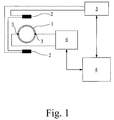
- Fig. 1 the structure of the magnetic-inductive is schematic Flow meter according to the preferred embodiment of the invention seen.
- the magnetic-inductive flow meter has one Line 1 through which a conductive medium, not shown flows through. With two field coils 2, a magnetic field is generated, which Line 1 and thus also the medium flowing through line 1 passes through. On line 1 are in the area in which the magnetic field interspersed, two measuring electrodes 3 are provided, with which one in the medium induced voltage can be tapped.
- the measuring electrodes 3 are in the known magnetic-inductive flow meters designed such that they are either galvanically or capacitively coupled to the flowing medium are.
- a special feature of the electromagnetic flowmeters is the proportionality between the measuring voltage and the flow rate averaged over the cross section of the line 1 of the medium.
- the output variable is that in the conductive medium induced voltage measured across the two measuring electrodes 3 is tapped.
- tension exists in proportionality, so that the in voltage induced in the conductive medium - as an initial value - depending of different magnetic fields or field currents - as input values - follows a linear voltage curve.
- a microcontroller 4 In the electromagnetic flow meter according to the preferred Embodiments of the invention are a microcontroller 4, a field coil supply 5 and an A / D converter 6 are provided.
- the microcontroller 4 is for the entire control of the electromagnetic flowmeter and its measuring operation responsible, and the field coil supply 5 takes over the supply of the field coils 2 with the field current.
- the A / D converter 6 is between the measuring electrodes 3 and the microcontroller 4th provided, receives as an input signal that induced in the conductive medium and tapped at the measuring electrodes 3 and gives one digitized value corresponding to this voltage to the microcontroller 4 out.
- the field coil supply 5 is also with the microcontroller 4 connected, namely to control or regulate the field coil supply 5, d. H. that supplied by the field coil supply 5 to the field current 2 Field current, or if the control of the field current in the Field coil supply 5 itself takes place, for the transmission of the present flowing field current.
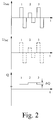
- the invention a reduction in the amplitude of the field current and thus also the magnetic field by 50%, so are other periodic ones Changes in the field current and thus the magnetic field possible.
- the field current can not only be reduced periodically but also can also be increased periodically, preferably reducing or an increase of at least 20% is to take place.
- the Changes in the field current and thus the magnetic field take place periodically.
- the present case is only for the sake of simple feasibility described preferred exemplary embodiment of the invention, that the change in the field current and thus the magnetic field periodically takes place and for an integer multiple of a half period of the field current is maintained.
- the settings of the self-test mode are included preferably chosen so that the change for two or three half-periods of the field current is maintained.
- the test in question i.e. the insertion of a period with one Field current with reduced amplitude, in the present case with half the amplitude performed every 5 s according to the preferred embodiment of the invention.
- the difference ⁇ Q of the flows determined in each case becomes over 100 such Tests averaged. It now turns out that this averaged value is greater than 1% of the full scale value for the flow Q is from the magnetic-inductive measuring device issued a warning "linearity". According to the embodiment of the invention described here is provided that this warning is given both optically and acoustically can be.
- the output of this warning indicates the following possible Error out: a non-linearity in the A / D converter 6, a non-linearity in the Circuit of the field coils 2, a defect in the field coils 2, in the lining the line 1 or on the measuring electrodes 3, an incorrect setting the calibration values and / or a zero point error of the A / D converter 6.
- the Entire measuring circuit including the measuring electrodes 3, the field coil supply 5 and the A / D converter 6, subjected to a self-test.
Landscapes
- Physics & Mathematics (AREA)
- Fluid Mechanics (AREA)
- General Physics & Mathematics (AREA)
- Electromagnetism (AREA)
- Measuring Volume Flow (AREA)
Applications Claiming Priority (2)
| Application Number | Priority Date | Filing Date | Title |
|---|---|---|---|
| DE10064738A DE10064738B4 (de) | 2000-12-22 | 2000-12-22 | Verfahren zur Prüfung eines magnetisch-induktiven Durchflußmeßgeräts |
| DE10064738 | 2000-12-22 |
Publications (3)
| Publication Number | Publication Date |
|---|---|
| EP1217337A2 true EP1217337A2 (fr) | 2002-06-26 |
| EP1217337A3 EP1217337A3 (fr) | 2003-05-07 |
| EP1217337B1 EP1217337B1 (fr) | 2014-05-28 |
Family
ID=7668785
Family Applications (1)
| Application Number | Title | Priority Date | Filing Date |
|---|---|---|---|
| EP01126066.8A Expired - Lifetime EP1217337B1 (fr) | 2000-12-22 | 2001-11-02 | Méthode pour vérifier le fonctionnement d'un dispositif de mesure du débit |
Country Status (5)
| Country | Link |
|---|---|
| US (1) | US6564612B2 (fr) |
| EP (1) | EP1217337B1 (fr) |
| JP (1) | JP2002243513A (fr) |
| DE (1) | DE10064738B4 (fr) |
| DK (1) | DK1217337T3 (fr) |
Cited By (5)
| Publication number | Priority date | Publication date | Assignee | Title |
|---|---|---|---|---|
| DE102004046238A1 (de) * | 2004-09-22 | 2006-03-23 | Endress + Hauser Flowtec Ag | Magnetisch-induktives Durchflussmessgerät |
| EP1698863A1 (fr) * | 2005-03-02 | 2006-09-06 | Endress+Hauser Flowtec AG | Procédé destiné au fonctionnement d'un débitmètre magnétique inductif |
| US7260486B2 (en) | 2004-09-22 | 2007-08-21 | Endress + Hauser Flowtec Ag | Method for operating and/or reviewing a magneto-inductive flow meter |
| WO2009038654A1 (fr) * | 2007-09-18 | 2009-03-26 | Rosemount Inc. | Transmetteur universel utilisable pour la mesure du flux magnétique |
| RU2396522C2 (ru) * | 2005-10-20 | 2010-08-10 | Эндресс + Хаузер Флоутек Аг | Магнитно-индуктивный расходомер |
Families Citing this family (23)
| Publication number | Priority date | Publication date | Assignee | Title |
|---|---|---|---|---|
| DE10356008B4 (de) * | 2003-11-27 | 2010-04-08 | Krohne Meßtechnik GmbH & Co KG | Verfahren zum Betreiben eines Meßgeräts |
| DE102005032134A1 (de) * | 2005-07-07 | 2007-01-18 | Endress + Hauser Wetzer Gmbh + Co Kg | Messvorrichtung zur Bestimmung und/oder Überwachung einer Prozessgröße und Verfahren zur Überwachung der Messvorrichtung |
| JP2010505121A (ja) * | 2006-09-29 | 2010-02-18 | ローズマウント インコーポレイテッド | 検証を備える磁気流量計 |
| DE102006050832B4 (de) | 2006-10-27 | 2012-07-26 | Infineon Technologies Ag | In-Betrieb-Test eines Signalpfades mittels wenigstens zweier Testsignale |
| DE102007021099A1 (de) | 2007-05-03 | 2008-11-13 | Endress + Hauser (Deutschland) Ag + Co. Kg | Verfahren zum Inbetriebnehmen und/oder Rekonfigurieren eines programmierbaren Feldmeßgeräts |
| EP1995679A1 (fr) * | 2007-05-25 | 2008-11-26 | Karl Storz GmbH & Co. KG | Procédé et dispositif destinés à la surveillance et/ou à la commande centrales d'au moins un appareil |
| GB2451284B (en) * | 2007-07-26 | 2012-10-17 | Abb Ltd | Flowmeter |
| JP6135924B2 (ja) * | 2013-07-08 | 2017-05-31 | 横河電機株式会社 | 電磁流量計 |
| US10663331B2 (en) * | 2013-09-26 | 2020-05-26 | Rosemount Inc. | Magnetic flowmeter with power limit and over-current detection |
| WO2015055303A1 (fr) | 2013-10-17 | 2015-04-23 | Krohne Ag | Système de mesure de débit magnéto-inductif |
| DE102013019182A1 (de) | 2013-10-17 | 2015-05-07 | Krohne Ag | Messrohr für magnetisch-induktive Durchflussmesssysteme |
| EP3043153B1 (fr) | 2015-01-05 | 2020-01-01 | Krohne AG | Débitmètre |
| DE102015116672A1 (de) | 2015-01-05 | 2016-07-07 | Krohne Ag | Durchflussmessgerät |
| DE102015116673A1 (de) | 2015-01-13 | 2016-07-14 | Krohne Ag | Magnetisch-induktives Durchflussmessgerät |
| DE102015116675A1 (de) | 2015-01-13 | 2016-07-14 | Krohne Ag | Magnetisch-induktives Durchflussmessgerät |
| EP3045875B1 (fr) | 2015-01-14 | 2020-01-15 | Krohne AG | Débitmètre à induction magnétique |
| EP3045874B1 (fr) | 2015-01-14 | 2020-01-08 | Krohne AG | Débitmètre magnéto-inductif |
| DE102015116679A1 (de) | 2015-01-14 | 2016-07-14 | Krohne Ag | Magnetisch-induktives Durchflussmessgerät |
| EP3048431B1 (fr) | 2015-01-20 | 2020-07-29 | Krohne AG | Débitmètre magnéto-inductif et procédé de fabrication d'une électrode de mesure |
| DE102015116676A1 (de) | 2015-01-20 | 2016-07-21 | Krohne Ag | Magnetisch-induktives Durchflussmessgerät und Verfahren zum Herstellen einer Messelektrode |
| CN109990873A (zh) * | 2018-01-02 | 2019-07-09 | 湖南睿图智能科技有限公司 | 一种机械式水表计量特性的检测方法 |
| CN109470289B (zh) * | 2018-09-18 | 2021-11-05 | 中国电力科学研究院有限公司 | 一种识别计量设备用能流量值反向事件的方法和系统 |
| CN116608887B (zh) * | 2023-07-17 | 2023-10-13 | 山东科技大学 | 一种投弃式海流剖面仪测试标定装置及方法 |
Citations (3)
| Publication number | Priority date | Publication date | Assignee | Title |
|---|---|---|---|---|
| DE4122225A1 (de) | 1991-07-04 | 1993-01-07 | Fischer & Porter Gmbh | Schaltungsanordnung zur ermittlung von fehlern in einer magnetisch-induktiven durchflussmessanordnung |
| GB2348011A (en) | 1996-01-17 | 2000-09-20 | Abb Instrumentation Ltd | Testing and calibration of electromagnetic flowmeters |
| DE19917261A1 (de) | 1999-04-16 | 2000-11-02 | Danfoss As | Elektromagnetische Durchflußmesseranordnung |
Family Cites Families (4)
| Publication number | Priority date | Publication date | Assignee | Title |
|---|---|---|---|---|
| JPH07111367B2 (ja) * | 1991-02-26 | 1995-11-29 | ディーエクスエル・インターナショナル・インコーポレーテッド | 流量センサおよびその検査方法 |
| US5379627A (en) * | 1992-06-03 | 1995-01-10 | A&E Manufacturing Co., Inc. | Tester for mass airflow sensor |
| DE19606826A1 (de) * | 1996-02-23 | 1997-08-28 | Knorr Bremse Electronic Gmbh | Verfahren und Vorrichtung zur Überprüfung eines Sensors |
| US6227031B1 (en) * | 1999-06-03 | 2001-05-08 | Skc, Inc. | Method and apparatus for calibrating gas samplers |
-
2000
- 2000-12-22 DE DE10064738A patent/DE10064738B4/de not_active Expired - Lifetime
-
2001
- 2001-11-02 EP EP01126066.8A patent/EP1217337B1/fr not_active Expired - Lifetime
- 2001-11-02 DK DK01126066.8T patent/DK1217337T3/da active
- 2001-12-03 US US10/006,501 patent/US6564612B2/en not_active Expired - Lifetime
- 2001-12-21 JP JP2001390383A patent/JP2002243513A/ja active Pending
Patent Citations (3)
| Publication number | Priority date | Publication date | Assignee | Title |
|---|---|---|---|---|
| DE4122225A1 (de) | 1991-07-04 | 1993-01-07 | Fischer & Porter Gmbh | Schaltungsanordnung zur ermittlung von fehlern in einer magnetisch-induktiven durchflussmessanordnung |
| GB2348011A (en) | 1996-01-17 | 2000-09-20 | Abb Instrumentation Ltd | Testing and calibration of electromagnetic flowmeters |
| DE19917261A1 (de) | 1999-04-16 | 2000-11-02 | Danfoss As | Elektromagnetische Durchflußmesseranordnung |
Cited By (8)
| Publication number | Priority date | Publication date | Assignee | Title |
|---|---|---|---|---|
| DE102004046238A1 (de) * | 2004-09-22 | 2006-03-23 | Endress + Hauser Flowtec Ag | Magnetisch-induktives Durchflussmessgerät |
| US7260486B2 (en) | 2004-09-22 | 2007-08-21 | Endress + Hauser Flowtec Ag | Method for operating and/or reviewing a magneto-inductive flow meter |
| RU2356014C2 (ru) * | 2004-09-22 | 2009-05-20 | Эндресс+Хаузер Флоутек Аг | Способ контроля магнитно-индуктивного расходомера |
| EP1698863A1 (fr) * | 2005-03-02 | 2006-09-06 | Endress+Hauser Flowtec AG | Procédé destiné au fonctionnement d'un débitmètre magnétique inductif |
| US7328112B2 (en) | 2005-03-02 | 2008-02-05 | Endress + Hauser Flowtec Ag | Method for operating a magneto-inductive flow meter |
| RU2396522C2 (ru) * | 2005-10-20 | 2010-08-10 | Эндресс + Хаузер Флоутек Аг | Магнитно-индуктивный расходомер |
| WO2009038654A1 (fr) * | 2007-09-18 | 2009-03-26 | Rosemount Inc. | Transmetteur universel utilisable pour la mesure du flux magnétique |
| US7516034B1 (en) | 2007-09-18 | 2009-04-07 | Rosemount Inc. | Magnetic flow transmitter having multiple flowtube data sets |
Also Published As
| Publication number | Publication date |
|---|---|
| EP1217337A3 (fr) | 2003-05-07 |
| US6564612B2 (en) | 2003-05-20 |
| DE10064738A1 (de) | 2002-07-04 |
| EP1217337B1 (fr) | 2014-05-28 |
| DK1217337T3 (da) | 2014-07-21 |
| DE10064738B4 (de) | 2004-02-12 |
| US20020112525A1 (en) | 2002-08-22 |
| JP2002243513A (ja) | 2002-08-28 |
Similar Documents
| Publication | Publication Date | Title |
|---|---|---|
| DE10064738B4 (de) | Verfahren zur Prüfung eines magnetisch-induktiven Durchflußmeßgeräts | |
| DE19917268B4 (de) | Verfahren zum Überprüfen eines elektromagnetischen Durchflußmessers und elektromagnetische Durchflußmesseranordnung | |
| EP1926972B1 (fr) | Procede pour faire fonctionner un dispositif electromagnetique de mesure de debit, et dispositif electromagnetique de mesure de debit correspondant | |
| EP2666023B1 (fr) | Appareil de mesure de courant | |
| DE19917261C5 (de) | Elektromagnetische Durchflußmesseranordnung | |
| DE102007052047A1 (de) | Verfahren und Einrichtung zur Messung von Fremdkörpern im Messmedium | |
| EP1536211B1 (fr) | Procédé pour faire fonctionner un débitmètre magnéto-inductif | |
| DE102014119453A1 (de) | Verfahren zur Defekterkennung der Signalleitung zwischen einer Elektrode und einer Mess- und/oder Auswerteeinheit eines magnetisch-induktiven Durchflussmessgerätes | |
| DE10356008B4 (de) | Verfahren zum Betreiben eines Meßgeräts | |
| EP2702370B1 (fr) | Procédé pour faire fonctionner un système de mesure par résonance | |
| EP1792144A1 (fr) | Procede de controle d'un debitmetre magneto-inductif | |
| EP3967988A1 (fr) | Procédé de fonctionnement d'un débitmètre magnétique-inductif et débitmètre magnétique-inductif correspondant | |
| EP1249687A2 (fr) | Débitmètre magnéto-inductif et procédé de mesure de débit magnéto-inductif | |
| EP1584902B1 (fr) | Débitmètre électromagnétique et procédé de fontionnement d'un débitmètre électromagnétique | |
| EP3293499A1 (fr) | Procédé de fonctionnement d'un débitmètre magnétique inductif et débitmètre magnétique inductif | |
| EP1586870B1 (fr) | Procédé pour la mesure magnéto-inductive d'un débit et débitmètre magnéto-inductif | |
| DE10312058A1 (de) | Vorrichtung zum Messen des Volumenstroms eines Messmediums in einem Messrohr | |
| DE102019126883A1 (de) | Verfahren zum Überwachen eines Meßgeräte-Systems | |
| EP1108989B1 (fr) | Dispositif pour la mesure d'un débit d'un fluide de mesure dans un conduit de mesure | |
| DE102021120452A1 (de) | Verfahren zum Betreiben eines Coriolis-Messgeräts | |
| EP1202031A1 (fr) | Procédé et appareil pour le contrôle de processus avec un capteur par induction magnétique | |
| DE102018122314B3 (de) | Anordnung zur Bestimmung eines Gesamtstroms in einer Leitung | |
| DE102012103037B4 (de) | Elektromagnetisch kraftkompensierende Kraftmessvorrichtung | |
| EP1649251A1 (fr) | Procede de determination magneto-inductive du debit d'un agent | |
| DE102009001833A1 (de) | Magnetisch-induktive Durchflussmesseinrichtung und Verfahren zum Betreiben derselben |
Legal Events
| Date | Code | Title | Description |
|---|---|---|---|
| PUAI | Public reference made under article 153(3) epc to a published international application that has entered the european phase |
Free format text: ORIGINAL CODE: 0009012 |
|
| AK | Designated contracting states |
Kind code of ref document: A2 Designated state(s): AT BE CH CY DE DK ES FI FR GB GR IE IT LI LU MC NL PT SE TR |
|
| AX | Request for extension of the european patent |
Free format text: AL;LT;LV;MK;RO;SI |
|
| PUAL | Search report despatched |
Free format text: ORIGINAL CODE: 0009013 |
|
| AK | Designated contracting states |
Designated state(s): AT BE CH CY DE DK ES FI FR GB GR IE IT LI LU MC NL PT SE TR |
|
| AX | Request for extension of the european patent |
Extension state: AL LT LV MK RO SI |
|
| 17P | Request for examination filed |
Effective date: 20030716 |
|
| AKX | Designation fees paid |
Designated state(s): AT BE CH CY DE DK ES FI FR GB GR IE IT LI LU MC NL PT SE TR |
|
| 17Q | First examination report despatched |
Effective date: 20060821 |
|
| REG | Reference to a national code |
Ref country code: DE Ref legal event code: R079 Ref document number: 50116401 Country of ref document: DE Free format text: PREVIOUS MAIN CLASS: G01F0001580000 Ipc: G01F0025000000 |
|
| GRAP | Despatch of communication of intention to grant a patent |
Free format text: ORIGINAL CODE: EPIDOSNIGR1 |
|
| RIC1 | Information provided on ipc code assigned before grant |
Ipc: G01F 1/60 20060101ALI20131202BHEP Ipc: G01F 25/00 20060101AFI20131202BHEP |
|
| INTG | Intention to grant announced |
Effective date: 20131220 |
|
| GRAS | Grant fee paid |
Free format text: ORIGINAL CODE: EPIDOSNIGR3 |
|
| GRAA | (expected) grant |
Free format text: ORIGINAL CODE: 0009210 |
|
| AK | Designated contracting states |
Kind code of ref document: B1 Designated state(s): AT BE CH CY DE DK ES FI FR GB GR IE IT LI LU MC NL PT SE TR |
|
| REG | Reference to a national code |
Ref country code: GB Ref legal event code: FG4D Free format text: NOT ENGLISH |
|
| REG | Reference to a national code |
Ref country code: CH Ref legal event code: EP |
|
| REG | Reference to a national code |
Ref country code: AT Ref legal event code: REF Ref document number: 670381 Country of ref document: AT Kind code of ref document: T Effective date: 20140615 |
|
| REG | Reference to a national code |
Ref country code: IE Ref legal event code: FG4D Free format text: LANGUAGE OF EP DOCUMENT: GERMAN |
|
| REG | Reference to a national code |
Ref country code: DE Ref legal event code: R096 Ref document number: 50116401 Country of ref document: DE Effective date: 20140703 |
|
| REG | Reference to a national code |
Ref country code: DK Ref legal event code: T3 Effective date: 20140715 |
|
| REG | Reference to a national code |
Ref country code: NL Ref legal event code: T3 |
|
| PG25 | Lapsed in a contracting state [announced via postgrant information from national office to epo] |
Ref country code: FI Free format text: LAPSE BECAUSE OF FAILURE TO SUBMIT A TRANSLATION OF THE DESCRIPTION OR TO PAY THE FEE WITHIN THE PRESCRIBED TIME-LIMIT Effective date: 20140528 Ref country code: GR Free format text: LAPSE BECAUSE OF FAILURE TO SUBMIT A TRANSLATION OF THE DESCRIPTION OR TO PAY THE FEE WITHIN THE PRESCRIBED TIME-LIMIT Effective date: 20140829 Ref country code: CY Free format text: LAPSE BECAUSE OF FAILURE TO SUBMIT A TRANSLATION OF THE DESCRIPTION OR TO PAY THE FEE WITHIN THE PRESCRIBED TIME-LIMIT Effective date: 20140528 |
|
| PG25 | Lapsed in a contracting state [announced via postgrant information from national office to epo] |
Ref country code: SE Free format text: LAPSE BECAUSE OF FAILURE TO SUBMIT A TRANSLATION OF THE DESCRIPTION OR TO PAY THE FEE WITHIN THE PRESCRIBED TIME-LIMIT Effective date: 20140528 |
|
| PG25 | Lapsed in a contracting state [announced via postgrant information from national office to epo] |
Ref country code: PT Free format text: LAPSE BECAUSE OF FAILURE TO SUBMIT A TRANSLATION OF THE DESCRIPTION OR TO PAY THE FEE WITHIN THE PRESCRIBED TIME-LIMIT Effective date: 20140929 |
|
| PG25 | Lapsed in a contracting state [announced via postgrant information from national office to epo] |
Ref country code: ES Free format text: LAPSE BECAUSE OF FAILURE TO SUBMIT A TRANSLATION OF THE DESCRIPTION OR TO PAY THE FEE WITHIN THE PRESCRIBED TIME-LIMIT Effective date: 20140528 |
|
| REG | Reference to a national code |
Ref country code: DE Ref legal event code: R097 Ref document number: 50116401 Country of ref document: DE |
|
| PLBE | No opposition filed within time limit |
Free format text: ORIGINAL CODE: 0009261 |
|
| STAA | Information on the status of an ep patent application or granted ep patent |
Free format text: STATUS: NO OPPOSITION FILED WITHIN TIME LIMIT |
|
| PG25 | Lapsed in a contracting state [announced via postgrant information from national office to epo] |
Ref country code: IT Free format text: LAPSE BECAUSE OF FAILURE TO SUBMIT A TRANSLATION OF THE DESCRIPTION OR TO PAY THE FEE WITHIN THE PRESCRIBED TIME-LIMIT Effective date: 20140528 |
|
| 26N | No opposition filed |
Effective date: 20150303 |
|
| REG | Reference to a national code |
Ref country code: DE Ref legal event code: R097 Ref document number: 50116401 Country of ref document: DE Effective date: 20150303 |
|
| PG25 | Lapsed in a contracting state [announced via postgrant information from national office to epo] |
Ref country code: BE Free format text: LAPSE BECAUSE OF NON-PAYMENT OF DUE FEES Effective date: 20141130 Ref country code: MC Free format text: LAPSE BECAUSE OF FAILURE TO SUBMIT A TRANSLATION OF THE DESCRIPTION OR TO PAY THE FEE WITHIN THE PRESCRIBED TIME-LIMIT Effective date: 20140528 Ref country code: LU Free format text: LAPSE BECAUSE OF FAILURE TO SUBMIT A TRANSLATION OF THE DESCRIPTION OR TO PAY THE FEE WITHIN THE PRESCRIBED TIME-LIMIT Effective date: 20141102 |
|
| REG | Reference to a national code |
Ref country code: IE Ref legal event code: MM4A |
|
| PG25 | Lapsed in a contracting state [announced via postgrant information from national office to epo] |
Ref country code: IE Free format text: LAPSE BECAUSE OF NON-PAYMENT OF DUE FEES Effective date: 20141102 |
|
| REG | Reference to a national code |
Ref country code: FR Ref legal event code: PLFP Year of fee payment: 15 |
|
| REG | Reference to a national code |
Ref country code: AT Ref legal event code: MM01 Ref document number: 670381 Country of ref document: AT Kind code of ref document: T Effective date: 20141102 |
|
| PG25 | Lapsed in a contracting state [announced via postgrant information from national office to epo] |
Ref country code: AT Free format text: LAPSE BECAUSE OF NON-PAYMENT OF DUE FEES Effective date: 20141102 |
|
| PG25 | Lapsed in a contracting state [announced via postgrant information from national office to epo] |
Ref country code: TR Free format text: LAPSE BECAUSE OF FAILURE TO SUBMIT A TRANSLATION OF THE DESCRIPTION OR TO PAY THE FEE WITHIN THE PRESCRIBED TIME-LIMIT Effective date: 20140528 |
|
| REG | Reference to a national code |
Ref country code: FR Ref legal event code: PLFP Year of fee payment: 16 |
|
| REG | Reference to a national code |
Ref country code: FR Ref legal event code: PLFP Year of fee payment: 17 |
|
| PGFP | Annual fee paid to national office [announced via postgrant information from national office to epo] |
Ref country code: NL Payment date: 20201125 Year of fee payment: 20 |
|
| PGFP | Annual fee paid to national office [announced via postgrant information from national office to epo] |
Ref country code: CH Payment date: 20201118 Year of fee payment: 20 Ref country code: DK Payment date: 20201123 Year of fee payment: 20 Ref country code: FR Payment date: 20201120 Year of fee payment: 20 Ref country code: GB Payment date: 20201120 Year of fee payment: 20 |
|
| PGFP | Annual fee paid to national office [announced via postgrant information from national office to epo] |
Ref country code: DE Payment date: 20210121 Year of fee payment: 20 |
|
| REG | Reference to a national code |
Ref country code: DE Ref legal event code: R071 Ref document number: 50116401 Country of ref document: DE |
|
| REG | Reference to a national code |
Ref country code: NL Ref legal event code: MK Effective date: 20211101 |
|
| REG | Reference to a national code |
Ref country code: DK Ref legal event code: EUP Expiry date: 20211102 |
|
| REG | Reference to a national code |
Ref country code: CH Ref legal event code: PL |
|
| REG | Reference to a national code |
Ref country code: GB Ref legal event code: PE20 Expiry date: 20211101 |
|
| PG25 | Lapsed in a contracting state [announced via postgrant information from national office to epo] |
Ref country code: GB Free format text: LAPSE BECAUSE OF EXPIRATION OF PROTECTION Effective date: 20211101 |