EP1217660B1 - Dissipateur de chaleur - Google Patents
Dissipateur de chaleur Download PDFInfo
- Publication number
- EP1217660B1 EP1217660B1 EP01128650A EP01128650A EP1217660B1 EP 1217660 B1 EP1217660 B1 EP 1217660B1 EP 01128650 A EP01128650 A EP 01128650A EP 01128650 A EP01128650 A EP 01128650A EP 1217660 B1 EP1217660 B1 EP 1217660B1
- Authority
- EP
- European Patent Office
- Prior art keywords
- baffle plate
- cooling device
- baseplate
- plate sections
- baffle
- Prior art date
- Legal status (The legal status is an assumption and is not a legal conclusion. Google has not performed a legal analysis and makes no representation as to the accuracy of the status listed.)
- Expired - Lifetime
Links
Images


Classifications
-
- H—ELECTRICITY
- H10—SEMICONDUCTOR DEVICES; ELECTRIC SOLID-STATE DEVICES NOT OTHERWISE PROVIDED FOR
- H10W—GENERIC PACKAGES, INTERCONNECTIONS, CONNECTORS OR OTHER CONSTRUCTIONAL DETAILS OF DEVICES COVERED BY CLASS H10
- H10W40/00—Arrangements for thermal protection or thermal control
- H10W40/40—Arrangements for thermal protection or thermal control involving heat exchange by flowing fluids
- H10W40/43—Arrangements for thermal protection or thermal control involving heat exchange by flowing fluids by flowing gases, e.g. forced air cooling
Definitions
- the invention relates to a cooling device for electronic components.
- heat sinks There is a wide variety of heat sinks known. Small heat sinks are adapted to the standardized housing of, for example, semiconductor devices and can be easily plugged. To improve the heat transfer between the semiconductor devices and the heat sink, it is known to use so-called thermal grease. For large heat sinks predominantly finished drawn aluminum profiles are used. Different versions of heat sinks are for example " Nizingmann, Dieter: Dasrete Maschinenbuch Elektronik, Part A, Franzis-Verlag, Kunststoff 1998 " known.
- the heat generated depends to a large extent on the clock frequency used.
- the higher the clock frequency the greater the power loss and thus the heat that must be dissipated to the environment.
- the clock frequency Due to advances in semiconductor technology, the clock frequency is now so high that hitherto known heat sink in the usual size is no longer sufficient, even if fans are used for forced cooling. The only way to ensure sufficient cooling, however, is therefore to further increase the heat sink, but this is not desirable or not possible for other structural and technical reasons.
- the base plate On the cooling fins a Strömungsleitvoriques is arranged, the base plate has a hole inside, and a baffle is arranged spirally around the hole, so that the air flow is passed from a fan arranged above the flow through the hole and on the cooling fins.
- the object of the present invention is to provide a cooling device by which a good cooling is achieved with little effort.
- the dimensions of the cooling device should be as small as possible.
- a cooling device with a base plate, which is brought into contact with a component to be cooled, a fan and a flow guide, which is formed by an arrangement of Leitblechabitesen, and directs a generated by the fan air flow to the base plate and is directly thermally conductive connected to the base plate, wherein in the Leitblechabsacrificingen in the connecting region between the Leitblechabitesen and the base plate recesses are provided for the formation of air ducts through which the air flow can escape laterally.
- the baffle sections fulfill a dual function. First, they steer the air flow generated by the fan optimized for the areas to be cooled, on the other hand, the baffle sections are also thermally conductive, so that they take over the function of cooling fins. Due to the inventive design of the baffle sections, the air is passed without much turbulence in a flow channel up to the Bäsisplatte, wherein the base plate is the hottest point of the cooling device. The air blown in from above experiences a deflection of 90 ° there. The air is then removed through the air channels. A turbulence takes place only at this point, which is much more effective than a turbulence in the field of cooling fins according to the prior art.
- the baffle sections are formed by a spirally curved baffle which is perpendicular to the base plate.
- the height of the baffle sections in the center of the cooling device is lower than outwards.
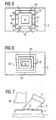
- FIG. 1 shows a cooling device according to the invention, which is fastened on a component 1 to be cooled is.
- a flow guide 3 is attached on the base plate 2.
- Both the base plate 2 and the flow guide 3 are made of a thermally highly conductive material. Particularly suitable are copper and aluminum materials.
- the flow guide 3 is connected to the base plate 2 so that a good heat transfer from the base plate 2 is ensured on the flow guide 3.
- a fan 4 with a fan hub 10 and fan blades 7 is placed on the flow guide 3. By the fan 4, an air flow 6 is generated, which enters from above into the flow guide 3 and this leaves through air ducts 5 again.
- FIG. 2 shows the plan view of the cooling device of FIG. 1.
- the flow-guiding device 3 is formed by an arrangement of Leitblechabitesen 11. This creates a flow channel which directs the blown in by the fan 4 air in defined paths.
- a spiral flow channel 12 is formed by the baffle sections 11.
- the orientation of the helical winding corresponds to the twist of the air flow 6 blown in by the fan 4.
- the guide plate sections 11 form an integral guide plate 9, which is shown unwound in FIG. In the center of the spiral winding there is a solid core 6.
- the heat transferred from the component 1 to be cooled to the base plate 2 is distributed in the base plate 2 and transmitted both to the solid core 6 and to the baffle sections 11. This ensures optimal heat distribution and optimum heat absorption capacity of the cooling device.
- baffle sections 11 Because of the dual function of baffle sections 11 to the flow line and the heat dissipation, it is important that the connection between the Leitblechabites 11 and the base plate 2 takes place thermally conductive.
- the cheapest conductivity has a solder joint, but also a connection with a thermally conductive adhesive is conceivable.
- the air injected from above into the flow-guiding device 3 is discharged again through air channels 5 which run on the surface of the base plate 2.
- the air ducts 5 are realized in a simple manner that are provided in the baffle 9 punched holes 13, wherein the arrangement is such that in the mounted on the base plate 2 state, a star-shaped arrangement of the air ducts 5 results.
- the production of a cooling device can be carried out so that a copper foil is wound around a solid copper core.
- the copper foil forms the baffle sections 11.
- the copper foil is ideally different in thickness over its height, for example between 0.2 mm and 0.5 mm.
- the advantage that results from this is described in one of the following sections.
- the initially tightly wound film rotates partially by relieving after winding partially on again. This process is intentional and must be done to a predetermined extent. To ensure this within acceptable tolerances, the material and the insertion force must be precisely defined.
- the resulting spiral is then soldered to the base plate 2, which is advantageously about 5 mm thick.
- the development shown in Figure 3 of the baffle 9 is substantially trapezoidal. At a first side edge 14, the settlement is attached to the solid core 6. This results in the assembled state, a flow guide, in which the height of the inner Leitblechabitese is less than the height of the outer baffle sections.
- the material thickness of the guide plate 9 decreases, starting from the lower edge 15 to the upper edge 16, as shown in Figure 4.
- This carries both the heat conduction function and the flow control function Bill. With regard to the heat conduction function, the heat flow decreases from the edge 15 towards the edge 16. This simply results from the release of heat to the environment.
- baffle sections 21 are not formed by a one-piece baffle, as is the case in the case of the embodiment of Figure 2, but it separate baffles are used, so that a plurality of flow channels 22 form.
- the air circulate only conditionally, so move in a rotational movement only within a flow channel 22, however, the air ducts 5 can be dimensioned accordingly, so that sufficient possibility for discharging the air flow 18 is present.
- baffle sections 31 are again formed in one piece by a baffle 32. This results, as in the embodiment of Figure 2, a spiral flow channel 23, the Leitblechabitese 31 are partially straight. A portion 33 of the outermost baffle portion is configured to provide close enough to the base plate 2 to vent the air in rotation through the spiral. At the top of this section 33, which, however, can not be seen in the figure, no opening is available to make a positive connection to a fan 4 possible.
- the baffle sections 11, 21 and 31 are arranged perpendicularly on the base plate 2.
- an embodiment is shown in which this is not the case, for example, to allow the installation of further system components from the space reasons.
- baffle was used. This is also to be understood that it may be, for example, a foil or a casting. The inventive function is nevertheless fulfilled.
Landscapes
- Cooling Or The Like Of Electrical Apparatus (AREA)
Claims (9)
- Dispositif de refroidissement avec- une plaque de base (2) qui peut être amenée en contact avec un composant (1) à refroidir,- un ventilateur (4) qui est disposé au-dessus de la plaque de base (2) et à distance de celle-ci, et- un dispositif (3) de guidage de flux, disposé entre la plaque de base (2) et le ventilateur (4), qui- est formé par un ensemble de segments (11 ; 21 ; 31) de tôle de guidage,- dirige sur la plaque de base (2) un flux d'air (18) produit par le ventilateur (4),- est directement relié en conduction thermique à la plaque de base (2),caractérisé en ce qu'un canal latéralement fermé est formé par les segments (11; 21; 31) de tôle de guidage dans une région distante de la plaque de base (2), et des évidements (13) sont prévus dans les segments (11 ; 21 ; 31) de tôle de guidage dans la région de liaison entre les segments (11 ; 21 ; 31) de tôle de guidage et la plaque de base (2), afin de former des canaux d'air (5) par lesquels le flux d'air peut s'échapper latéralement.
- Dispositif de refroidissement selon la revendication 1, caractérisé en ce que les segments (11 ; 21 ; 31) de tôle de guidage se dressent verticalement sur la plaque de base (2).
- Dispositif de refroidissement selon la revendication 1, caractérisé en ce que les segments (11) de tôle de guidage sont formés par une tôle de guidage (9) courbée en spirale.
- Dispositif de refroidissement selon la revendication 1, caractérisé en ce que les segments (21) de tôle de guidage sont des tôles de guidage individuelles.
- Dispositif de refroidissement selon la revendication 3, caractérisé en ce que la hauteur de la tôle de guidage augmente de l'intérieur vers l'extérieur.
- Dispositif de refroidissement selon la revendication 1, caractérisé en ce que la hauteur des segments de tôle de guidage situés à l'intérieur est inférieure à la hauteur des segments de tôle de guidage situés à l'extérieur.
- Dispositif de refroidissement selon la revendication 1, caractérisé en ce que l'épaisseur des segments de tôle de guidage diminue en partant de la plaque de base (2).
- Dispositif de refroidissement selon l'une quelconque des revendications 1 à 7, caractérisé en ce que le ventilateur (4) est relié en engagement positif au segment de tôle de guidage le plus extérieur.
- Dispositif de refroidissement selon l'une quelconque des revendications 1 à 8, caractérisé en ce que le dispositif (3) de guidage de flux possède un noyau massif (6) qui est reliée en conduction thermique à la plaque de base (2) et aux segments (11 ; 31) de tôle de guidage.
Applications Claiming Priority (2)
| Application Number | Priority Date | Filing Date | Title |
|---|---|---|---|
| DE10063306 | 2000-12-19 | ||
| DE10063306A DE10063306A1 (de) | 2000-12-19 | 2000-12-19 | Kühlvorrichtung |
Publications (3)
| Publication Number | Publication Date |
|---|---|
| EP1217660A2 EP1217660A2 (fr) | 2002-06-26 |
| EP1217660A3 EP1217660A3 (fr) | 2004-10-06 |
| EP1217660B1 true EP1217660B1 (fr) | 2008-01-16 |
Family
ID=7667797
Family Applications (1)
| Application Number | Title | Priority Date | Filing Date |
|---|---|---|---|
| EP01128650A Expired - Lifetime EP1217660B1 (fr) | 2000-12-19 | 2001-11-30 | Dissipateur de chaleur |
Country Status (2)
| Country | Link |
|---|---|
| EP (1) | EP1217660B1 (fr) |
| DE (2) | DE10063306A1 (fr) |
Families Citing this family (3)
| Publication number | Priority date | Publication date | Assignee | Title |
|---|---|---|---|---|
| DE102004039228B4 (de) * | 2004-08-12 | 2007-04-19 | Fujitsu Siemens Computers Gmbh | Kühlvorrichtung |
| EP1747917B1 (fr) | 2005-07-28 | 2009-10-21 | ebm-papst St. Georgen GmbH & Co. KG | Élément de chauffage |
| DE202008017800U1 (de) * | 2008-11-20 | 2010-07-15 | Talanin, Yru V. | Einrichtung zum Heizen und Kühlen eines Stromrichters |
Family Cites Families (14)
| Publication number | Priority date | Publication date | Assignee | Title |
|---|---|---|---|---|
| US3592260A (en) * | 1969-12-05 | 1971-07-13 | Espey Mfg & Electronics Corp | Heat exchanger with inner guide strip |
| US4777560A (en) * | 1987-09-02 | 1988-10-11 | Microelectronics And Computer Technology Corporation | Gas heat exchanger |
| US4918571A (en) * | 1987-03-31 | 1990-04-17 | Amp Incorporated | Chip carrier with energy storage means |
| US5000254A (en) * | 1989-06-20 | 1991-03-19 | Digital Equipment Corporation | Dynamic heat sink |
| WO1994004013A1 (fr) * | 1992-08-06 | 1994-02-17 | Pfu Limited | Refroidisseur destine a un generateur de chaleur |
| JP2625398B2 (ja) * | 1995-03-17 | 1997-07-02 | 日本電気株式会社 | マルチチップ冷却装置 |
| US5630469A (en) * | 1995-07-11 | 1997-05-20 | International Business Machines Corporation | Cooling apparatus for electronic chips |
| US5563768A (en) * | 1995-08-31 | 1996-10-08 | At&T Global Information Solutions Company | Heat source cooling apparatus and method utilizing mechanism for dividing a flow of cooling fluid |
| US5740014A (en) * | 1996-12-11 | 1998-04-14 | Lin; Chun Sheng | CPU heat sink |
| US6061239A (en) * | 1997-05-16 | 2000-05-09 | Psc Computer Products | Cam-type retainer clip for heat sinks for electronic integrated circuits |
| US6031720A (en) * | 1997-11-14 | 2000-02-29 | The Panda Project | Cooling system for semiconductor die carrier |
| JP2000244162A (ja) * | 1998-12-25 | 2000-09-08 | Denso Corp | 冷却装置 |
| US6148907A (en) * | 1999-11-19 | 2000-11-21 | Yen Sun Technology Corp. | Heat exchange structure for a heat source |
| DE10013863A1 (de) * | 2000-03-21 | 2001-10-04 | Fujitsu Siemens Computers Gmbh | Luftleithaube |
-
2000
- 2000-12-19 DE DE10063306A patent/DE10063306A1/de not_active Ceased
-
2001
- 2001-11-30 DE DE50113500T patent/DE50113500D1/de not_active Expired - Lifetime
- 2001-11-30 EP EP01128650A patent/EP1217660B1/fr not_active Expired - Lifetime
Also Published As
| Publication number | Publication date |
|---|---|
| EP1217660A3 (fr) | 2004-10-06 |
| DE50113500D1 (de) | 2008-03-06 |
| DE10063306A1 (de) | 2002-07-04 |
| EP1217660A2 (fr) | 2002-06-26 |
Similar Documents
| Publication | Publication Date | Title |
|---|---|---|
| EP1395752B1 (fr) | Dispositif de refroidissement concu pour un aerogenerateur | |
| EP2567423B1 (fr) | Dispositif de refroidissement d'une batterie | |
| DE102016202416B4 (de) | Rotorwellenanordnung und Verfahren zu dessen Herstellung | |
| DE60128585T2 (de) | Gasgekühlte dynamoelektrische Maschine | |
| DE102006043169B4 (de) | Elektrische Maschine mit einem innengekühlten Läufer | |
| DE102020205124B4 (de) | Wärmeabführstruktur | |
| DE3223624C2 (de) | Kühlkörper für elektrische Bauelemente | |
| EP1459378B1 (fr) | Dispositif de refroidissement pour puce, et procede de realisation | |
| EP3541157B1 (fr) | Module électronique doté d'un boîtier à nervures de refroidissement | |
| WO2021032238A1 (fr) | Refroidissement de stator | |
| WO2016142190A1 (fr) | Machine électrique dotée d'un radiateur | |
| DE1913163A1 (de) | Transformator mit Waermeableitkoerper | |
| EP1217660B1 (fr) | Dissipateur de chaleur | |
| DE102005031262B4 (de) | Kühlkörpervorrichtung | |
| EP3182565A1 (fr) | Boîtier électronique comprenant des ailettes | |
| DE20307981U1 (de) | Axialventilator für Computer | |
| EP3784012B1 (fr) | Électronique de puissance pour un chariot de manutention | |
| EP3459110B1 (fr) | Unité de boîte de refroidissement et système électronique de puissance doté d'une unité de boîte de refroidissement | |
| EP4268552B1 (fr) | Dispositif de refroidissement destiné au refroidissement d'un module semi-conducteur et onduleur pourvu de dispositif de refroidissement | |
| WO2012055402A1 (fr) | Refroidisseur pour unité centrale (cpu) | |
| DE102019102146A1 (de) | Relais mit Kühlfunktion | |
| DE20016460U1 (de) | Luftstromführende Lüfterhaube | |
| DE102022102172A1 (de) | Rotor für einen Außenläufermotor sowie Außenläufermotor | |
| DE19810628A1 (de) | Belüftungssystem für die Erregerwicklung großer Schenkelpolmaschinen | |
| EP4199672B1 (fr) | Dispositif de condensation de condensat, ensemble électronique et procédé de fabrication d'un dispositif de condensation de condensat |
Legal Events
| Date | Code | Title | Description |
|---|---|---|---|
| PUAI | Public reference made under article 153(3) epc to a published international application that has entered the european phase |
Free format text: ORIGINAL CODE: 0009012 |
|
| AK | Designated contracting states |
Kind code of ref document: A2 Designated state(s): AT BE CH CY DE DK ES FI FR GB GR IE IT LI LU MC NL PT SE TR |
|
| AX | Request for extension of the european patent |
Free format text: AL;LT;LV;MK;RO;SI |
|
| RAP1 | Party data changed (applicant data changed or rights of an application transferred) |
Owner name: FUJITSU SIEMENS COMPUTERS GMBH |
|
| PUAL | Search report despatched |
Free format text: ORIGINAL CODE: 0009013 |
|
| AK | Designated contracting states |
Kind code of ref document: A3 Designated state(s): AT BE CH CY DE DK ES FI FR GB GR IE IT LI LU MC NL PT SE TR |
|
| AX | Request for extension of the european patent |
Extension state: AL LT LV MK RO SI |
|
| 17P | Request for examination filed |
Effective date: 20050404 |
|
| AKX | Designation fees paid |
Designated state(s): DE FR GB |
|
| 17Q | First examination report despatched |
Effective date: 20060119 |
|
| GRAP | Despatch of communication of intention to grant a patent |
Free format text: ORIGINAL CODE: EPIDOSNIGR1 |
|
| GRAS | Grant fee paid |
Free format text: ORIGINAL CODE: EPIDOSNIGR3 |
|
| GRAA | (expected) grant |
Free format text: ORIGINAL CODE: 0009210 |
|
| AK | Designated contracting states |
Kind code of ref document: B1 Designated state(s): DE FR GB |
|
| REG | Reference to a national code |
Ref country code: GB Ref legal event code: FG4D Free format text: NOT ENGLISH |
|
| REF | Corresponds to: |
Ref document number: 50113500 Country of ref document: DE Date of ref document: 20080306 Kind code of ref document: P |
|
| GBT | Gb: translation of ep patent filed (gb section 77(6)(a)/1977) |
Effective date: 20080413 |
|
| ET | Fr: translation filed | ||
| PLBE | No opposition filed within time limit |
Free format text: ORIGINAL CODE: 0009261 |
|
| STAA | Information on the status of an ep patent application or granted ep patent |
Free format text: STATUS: NO OPPOSITION FILED WITHIN TIME LIMIT |
|
| 26N | No opposition filed |
Effective date: 20081017 |
|
| REG | Reference to a national code |
Ref country code: DE Ref legal event code: R084 Ref document number: 50113500 Country of ref document: DE |
|
| REG | Reference to a national code |
Ref country code: GB Ref legal event code: 746 Effective date: 20110527 |
|
| REG | Reference to a national code |
Ref country code: DE Ref legal event code: R081 Ref document number: 50113500 Country of ref document: DE Owner name: FUJITSU TECHNOLOGY SOLUTIONS INTELLECTUAL PROP, DE Free format text: FORMER OWNER: FUJITSU SIEMENS COMPUTERS GMBH, 80807 MUENCHEN, DE Effective date: 20111229 Ref country code: DE Ref legal event code: R082 Ref document number: 50113500 Country of ref document: DE Representative=s name: EPPING HERMANN FISCHER, PATENTANWALTSGESELLSCH, DE Effective date: 20111229 |
|
| REG | Reference to a national code |
Ref country code: FR Ref legal event code: PLFP Year of fee payment: 15 |
|
| PGFP | Annual fee paid to national office [announced via postgrant information from national office to epo] |
Ref country code: GB Payment date: 20151123 Year of fee payment: 15 Ref country code: DE Payment date: 20151119 Year of fee payment: 15 |
|
| PGFP | Annual fee paid to national office [announced via postgrant information from national office to epo] |
Ref country code: FR Payment date: 20151124 Year of fee payment: 15 |
|
| REG | Reference to a national code |
Ref country code: DE Ref legal event code: R119 Ref document number: 50113500 Country of ref document: DE |
|
| GBPC | Gb: european patent ceased through non-payment of renewal fee |
Effective date: 20161130 |
|
| REG | Reference to a national code |
Ref country code: FR Ref legal event code: ST Effective date: 20170731 |
|
| PG25 | Lapsed in a contracting state [announced via postgrant information from national office to epo] |
Ref country code: FR Free format text: LAPSE BECAUSE OF NON-PAYMENT OF DUE FEES Effective date: 20161130 |
|
| PG25 | Lapsed in a contracting state [announced via postgrant information from national office to epo] |
Ref country code: GB Free format text: LAPSE BECAUSE OF NON-PAYMENT OF DUE FEES Effective date: 20161130 Ref country code: DE Free format text: LAPSE BECAUSE OF NON-PAYMENT OF DUE FEES Effective date: 20170601 |