EP1217683A2 - Mikrowellenfenster - Google Patents
Mikrowellenfenster Download PDFInfo
- Publication number
- EP1217683A2 EP1217683A2 EP01125605A EP01125605A EP1217683A2 EP 1217683 A2 EP1217683 A2 EP 1217683A2 EP 01125605 A EP01125605 A EP 01125605A EP 01125605 A EP01125605 A EP 01125605A EP 1217683 A2 EP1217683 A2 EP 1217683A2
- Authority
- EP
- European Patent Office
- Prior art keywords
- microwave
- dielectric
- window according
- microwave window
- disk
- Prior art date
- Legal status (The legal status is an assumption and is not a legal conclusion. Google has not performed a legal analysis and makes no representation as to the accuracy of the status listed.)
- Withdrawn
Links
Images


Classifications
-
- G—PHYSICS
- G01—MEASURING; TESTING
- G01F—MEASURING VOLUME, VOLUME FLOW, MASS FLOW OR LIQUID LEVEL; METERING BY VOLUME
- G01F23/00—Indicating or measuring liquid level or level of fluent solid material, e.g. indicating in terms of volume or indicating by means of an alarm
- G01F23/22—Indicating or measuring liquid level or level of fluent solid material, e.g. indicating in terms of volume or indicating by means of an alarm by measuring physical variables, other than linear dimensions, pressure or weight, dependent on the level to be measured, e.g. by difference of heat transfer of steam or water
- G01F23/28—Indicating or measuring liquid level or level of fluent solid material, e.g. indicating in terms of volume or indicating by means of an alarm by measuring physical variables, other than linear dimensions, pressure or weight, dependent on the level to be measured, e.g. by difference of heat transfer of steam or water by measuring the variations of parameters of electromagnetic or acoustic waves applied directly to the liquid or fluent solid material
- G01F23/284—Electromagnetic waves
-
- H—ELECTRICITY
- H01—ELECTRIC ELEMENTS
- H01P—WAVEGUIDES; RESONATORS, LINES, OR OTHER DEVICES OF THE WAVEGUIDE TYPE
- H01P1/00—Auxiliary devices
- H01P1/08—Dielectric windows
Definitions
- the invention relates to a microwave window for spatial separation and microwave connection of an outer microwave conductor from or with an inner microwave conductor or a horn, with a microwave permeable Pass-through disc and with one of the attachment of the Metallic fastener serving as a transmission disk.
- a microwave window is e.g. known from DE 195 42 525 A1.
- Microwave windows of the type in question are generally used for Separation of a microwave transmitter from one usually in one Containing liquid or solid medium. Such arrangements are used especially for level measurements based on the radar principle used in industrial plants. For such industrial level measurement systems are usually specific requirements on the mechanical Parts provided with the medium in the container or the associated Atmosphere. In such a container can Negative pressure or very high positive pressure, explosive atmospheres, very high or very low temperatures as well as aggressive and / or corrosive Media.
- the microwave window is used for the microwave transmitter with their sensitive electronic components the influences of the conditions in the container holding the medium to protect.
- a microwave-permeable, glass or ceramic passage disk in one metallic fastener is attached by the passage disk in the fastener is melted or sintered.
- the fastener for the pass-through disk it can be one such Act component, its only function in the holder of the pass-through disk there is, on the other hand, the fastener of one Wall e.g. of a container are formed, the outer microwave conductor and the inner microwave guide on opposite sides this wall are provided.
- the transmission disc is installed tension-free, that is, it is not itself subjected to force.
- the microwave transmission device itself is thus in the Fastener melted or sintered in passage disk from the conditions in the container in which the medium is located. Aggressive and / or corrosive media can thus the microwave transmitter do nothing.
- microwave window which is a hermetically sealed separation or connection of an external one Microwave conductor with an inner microwave conductor or Horn blaster allows, the attachment of the passage disk on simple and can be implemented safely.
- the microwave window according to the invention in which the previously shown and derived problem is solved, is based on the above generic microwave window characterized in that that the fastener is coated with a dielectric and the Pass-through disk melted into the fastener via the dielectric or is glued in.
- the fastener can e.g. be a bracket that is specifically and exclusively for the Holding the passage disk is provided, but on the other hand also Wall of a container in which the medium is filled.
- a microwave permeable Passage disks are - as in the prior art - essentially suitable passage discs made of glass or ceramic. Their shape is basically arbitrary, preferably the passage disks however, essentially circular, particularly preferably circular.
- the passage disk in the fastener is coated with the dielectric.
- the in that Fastener disc used is therefore not in direct Contact with the passage disk, but is with this indirectly through the Dielectric connected.
- This connection is made either by means of a separate adhesive or by melting the passage disk into the recess coated with the dielectric in the fastening means.
- Such a melting of the pass-through disk includes Melting of the dielectric, melting of the transmission disk, however also a simultaneous melting of both the dielectric and the Transparent disk.
- Such a microwave window is thus according to the invention achieved, in a simple and reliable manner, the passage disk practically tension-free, i.e. without excessive stress, in the fastener is attached pressure-tight.
- the partial coating mentioned above is already in accordance with the invention of the fastener with the dielectric is sufficient.
- the fastener at least on its the inner microwave conductor or the side facing the horn, completely with the dielectric is coated. It is very particularly preferred in this context however, to completely coat the fastener with the dielectric. Is on the opposite of the outer microwave conductor A horn is provided on the side of the microwave window such a horn can be used, the surface of which is uncoated is.
- the surface of the horn - preferably completely - is coated with a dielectric.
- the layer thickness of the Dielectric do not exceed 2 mm to avoid such high charges of the dielectric, with the prescribed explosion protection measures would not be compatible.
- Preferred materials for the Dielectric are plastic, such as PTFE, PFA, FEP or PVDF, and enamel.
- enamel when using enamel as a dielectric, it is stress-free Inclusion of the passage disk in the fastener particularly advantageous, because there is no chipping of the enamel layer from the passage disk is to be feared.
- the passage disk is not held in the fastener by a tension or press fit, but in that the passage disk over the dielectric, so in the present case the enamel into which the fastener is melted or glued.
- the microwave window in terms of its permeability to microwave radiation be improved in that the thickness of the transmission disk is an integer Is a multiple of the wavelength of the microwaves.
- the thickness of the transmission disk must of course include the dielectric constant of the material of the transmission disc and the speed of propagation the microwave radiation within the microwave guide is taken into account become.
- the permeability of the microwave window for microwave radiation further be improved in that to adjust the wave resistance the transmission disk to the wave resistance of the microwave conductor or the horn is at least a one-piece molded body is provided on the passage disk.
- the passage disk with the adapter body eliminates transitions between the passage disk and the adapter body, so that on the one hand with reflections of the microwave radiation in such transitions Area of the microwave window can be avoided and on the other hand between the passage disk and the adapter body no intermediate areas are present in which an aggressive and / or corrosive medium can penetrate.
- the microwave window according to the invention must have particularly high pressure differences withstand, so the microwave window according to the invention from one side with a clear positive or negative pressure, it is provided according to a preferred development of the invention that the passage disk in the fastener at least in one direction a normal of the passage disk is held by means of a positive connection.
- the passage disk is circular and on the side on which it is held by positive locking, a smaller diameter has than on the opposite side. The application with the higher pressure then takes place on the side on which the passage disk has the larger diameter.
- the passage disk has a conical shape or has a stepped edge.
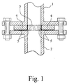
- FIG. 1 is a microwave window according to a first preferred embodiment the invention can be seen that for spatial separation and microwave connection of an outer microwave conductor 1 with a inner microwave guide 2 is used.
- a microwave permeable Passage disk 3 made of glass is arranged in a metallic fastening means 4 and together with this forms the actual microwave window.
- both the passage disk 3 and the metallic fastening means 4 executed round. Accordingly, is in the metallic fastener 4 a circular bore is provided for receiving the passage disk 3.
- the surface of the metallic fastener delimiting this bore 4 and its surface facing the inner microwave conductor 2 are coated with a dielectric 5, the present one Enamel layer is formed.
- the attachment of the passage disk 3 in the metallic fastener 4 is according to the first preferred embodiment of the invention in that the enamel layer in the area of the hole in the metallic Fastener 4 melted and the glass passage disk 3 inserted into the recess with the melted enamel layer has been so that after cooling the enamel layer a mechanical fixed mounting of the passage disk 3 in the metallic fastener 4 has been achieved.
- This connection is also hermetic tight, also pressure tight, while at the same time being tension-free Holding the passage disk 3 in the metallic fastening means 4 is guaranteed.
- the enamel layer on the metallic Fastening means 4 achieves that chemically aggressive and / or corrosive Media can not attack the metallic fastener 4.
- a microwave window according to a second preferred Embodiment of the invention can be seen.
- this microwave window is a complete coating of the surface of the fastener 4 provided with enamel.
- a glass passage disk 3 used, both on their outer microwave 1 as well as on their side facing the inner microwave conductor 2 in each case an adaptation body formed in one piece with the passage disk 3 having.
- the permeability of the microwave window is due to these adaptation bodies improved for microwave radiation because of the wave resistance the transmission disk 3 to the characteristic impedance of the microwave conductors 1, 2 is adjusted.
- FIG. 2 While in the microwave window shown in FIG. 2 according to the second preferred embodiment of the invention essentially 3 are a microwave window in FIG according to a third preferred embodiment of the invention shown, in which the passage disk 3 both on its to the outside Microwave guide 1 facing side as well as on its inner microwave guide 2 facing side has a substantially conical recess has, which also for adjusting the characteristic impedance of the Pass plate 3 to the wave resistance of the microwave conductors 1, 2 is used.
- FIG. 4 shows a microwave window according to a fourth preferred one Embodiment of the invention, in which an adaptation of the Wave resistance of the transmission disk 3 to the wave resistance of the microwave conductor 1, 2 is achieved in that relative to the longitudinal axis of the microwave guide 1, 2 the microwave window is not vertical, but oblique is installed between the two microwave conductors 1, 2.
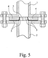
- Fig. 5 is a microwave window according to a fifth preferred Embodiment of the invention can be seen in which the measure is realized that the passage disk 3 in the fastening means 4 at least in a direction of a normal to the passage disk 3 by means of positive locking is held.
- the passage disk 3 can not upwards, that is, in the direction to the outer microwave conductor 1, dodge, because the passage disc 3 is conical, i.e. on its upper side a smaller diameter has as on its bottom.
- this shape of the passage disk 3 becomes the microwave window according to the fifth preferred embodiment the invention applied from below with an overpressure.
Landscapes
- Physics & Mathematics (AREA)
- Electromagnetism (AREA)
- Thermal Sciences (AREA)
- Fluid Mechanics (AREA)
- General Physics & Mathematics (AREA)
- Waveguide Connection Structure (AREA)
- Measurement Of Levels Of Liquids Or Fluent Solid Materials (AREA)
- Plasma Technology (AREA)
Abstract
Description
- Fig. 1
- ein Mikrowellenfenster gemäß einem ersten bevorzugten Ausführungsbeispiel der Erfindung im Schnitt,
- Fig. 2
- ein Mikrowellenfenster gemäß einem zweiten bevorzugten Ausführungsbeispiel der Erfindung im Schnitt,
- Fig. 3
- ein Mikrowellenfenster gemäß einem dritten bevorzugten Ausführungsbeispiel der Erfindung im Schnitt,
- Fig. 4
- ein Mikrowellenfenster gemäß einem vierten bevorzugten Ausführungsbeispiel der Erfindung im Schnitt und
- Fig. 5
- ein Mikrowellenfenster gemäß einem fünften bevorzugten Ausführungsbeispiel der Erfindung im Schnitt.
Claims (12)
- Mikrowellenfenster zur räumlichen Trennung und mikrowellenmäßigen Verbindung eines äußeren Mikrowellenleiters (1) von bzw. mit einem inneren Mikrowellenleiter (2) oder einem Hornstrahler, mit einer mikrowellendurchlässigen Durchlaßscheibe (3) und mit einem der Befestigung der Durchlaßscheibe dienenden metallischen Befestigungsmittel (4),
dadurch gekennzeichnet, daß das Befestigungsmittel (4) mit einem Dielektrikum (5) beschichtet ist und die Durchlaßscheibe (3) über das Dielektrikum (5) in das Befestigungsmittel (4) eingeschmolzen oder eingeklebt ist. - Mikrowellenfenster nach Anspruch 1, dadurch gekennzeichnet, daß das Befestigungsmittel (4) vollständig mit dem Dielektrikum (5) beschichtet ist.
- Mikrowellenfenster nach Anspruch 1 oder 2 mit einem Hornstrahler, dadurch gekennzeichnet, daß die Oberfläche des Hornstrahlers mit einem Dielektrikum (5) beschichtet ist.
- Mikrowellenfenster nach einem der Ansprüche 1 bis 3, dadurch gekennzeichnet, daß die Schichtdicke des Dielektrikums (5) maximal 2 mm beträgt.
- Mikrowellenfenster nach einem der Ansprüche 1 bis 4, dadurch gekennzeichnet, daß das Dielektrikum (5) aus Kunststoff- vorzugsweise aus PTFE, FPA, FEP oder PVDF - besteht.
- Mikrowellenfenster nach einem der Ansprüche 1 bis 4, dadurch gekennzeichnet, daß das Dielektrikum (5) aus Email besteht.
- Mikrowellenfenster nach einem der Ansprüche 1 bis 6, dadurch gekennzeichnet, daß die Dicke der Durchlaßscheibe (3) ein ganzzahliges Vielfaches der Wellenlänge der Mikrowellen beträgt.
- Mikrowellenfenster nach einem der Ansprüche 1 bis 7, dadurch gekennzeichnet, daß die Durchlaßscheibe (3) zur Anpassung des Wellenwiderstandes der Durchlaßscheibe (3) an den Wellenwiderstand der Mikrowellenleiter (1, 2) bzw. des Hornstrahlers wenigstens einen einstückig angeformten Anpassungskörper aufweist.
- Mikrowellenfenster nach einem der Ansprüche 1 bis 8, dadurch gekennzeichnet, daß die Durchlaßscheibe (3) in dem Befestigungsmittel (4) wenigstens in einer Richtung der Normalen der Durchlaßscheibe (3) mittels Formschluß gehalten ist.
- Mikrowellenfenster nach Anspruch 9, dadurch gekennzeichnet, daß die Durchlaßscheibe (3) kreisförmig ist und auf der Seite, auf der sie durch Formschluß gehalten ist, einen geringeren Durchmesser aufweist als auf der gegenüberliegenden Seite.
- Mikrowellenfenster nach Anspruch 9 oder 10, dadurch gekennzeichnet, daß die Durchlaßscheibe (3) eine konische Form aufweist.
- Mikrowellenfenster nach Anspruch 9 oder 10, dadurch gekennzeichnet, daß die Durchlaßscheibe (3) einen stufenförmigen Rand aufweist.
Applications Claiming Priority (2)
| Application Number | Priority Date | Filing Date | Title |
|---|---|---|---|
| DE10060069A DE10060069C1 (de) | 2000-12-01 | 2000-12-01 | Mikrowellenfenster |
| DE10060069 | 2000-12-01 |
Publications (2)
| Publication Number | Publication Date |
|---|---|
| EP1217683A2 true EP1217683A2 (de) | 2002-06-26 |
| EP1217683A3 EP1217683A3 (de) | 2004-01-02 |
Family
ID=7665636
Family Applications (1)
| Application Number | Title | Priority Date | Filing Date |
|---|---|---|---|
| EP01125605A Withdrawn EP1217683A3 (de) | 2000-12-01 | 2001-10-26 | Mikrowellenfenster |
Country Status (4)
| Country | Link |
|---|---|
| US (1) | US20020067229A1 (de) |
| EP (1) | EP1217683A3 (de) |
| JP (1) | JP2002290102A (de) |
| DE (1) | DE10060069C1 (de) |
Cited By (1)
| Publication number | Priority date | Publication date | Assignee | Title |
|---|---|---|---|---|
| CN110501052A (zh) * | 2018-05-17 | 2019-11-26 | Vega格里沙贝两合公司 | 用于雷达物位测量设备的紧固组件 |
Families Citing this family (27)
| Publication number | Priority date | Publication date | Assignee | Title |
|---|---|---|---|---|
| JP3924748B2 (ja) | 2000-09-20 | 2007-06-06 | 東洋紡績株式会社 | 種々の環境ストレス耐性を改良した植物、その作出方法、並びにポリアミン代謝関連酵素遺伝子 |
| JP3843081B2 (ja) | 2003-05-16 | 2006-11-08 | 株式会社インテリジェント・コスモス研究機構 | Nrdガイド変換器 |
| WO2007017170A1 (en) * | 2005-08-04 | 2007-02-15 | Vega Grieshaber Kg | Potential separation for fill level radar |
| US8711049B2 (en) | 2005-08-04 | 2014-04-29 | Vega Grieshaber Kg | Potential separation for filling level radar |
| DE102005036715A1 (de) * | 2005-08-04 | 2007-02-15 | Vega Grieshaber Kg | Potentialtrennung für Füllstandradar |
| DE102005036844A1 (de) * | 2005-08-04 | 2007-02-08 | Vega Grieshaber Kg | Potentialtrennung für Füllstandradar |
| EP2023097B1 (de) * | 2007-07-31 | 2015-03-04 | Siemens Aktiengesellschaft | Radar-Füllstandsmessgerät |
| JP4977197B2 (ja) * | 2009-12-25 | 2012-07-18 | 日本電信電話株式会社 | 導波管封止材 |
| JP2011135496A (ja) * | 2009-12-25 | 2011-07-07 | Nippon Telegr & Teleph Corp <Ntt> | 封止機能付導波管フィルタ |
| DE102011010801B4 (de) * | 2011-02-09 | 2016-01-07 | Krohne Messtechnik Gmbh | Mikrowellensendeeinrichtung und Füllstandmessgerät |
| DE102011112045A1 (de) * | 2011-09-01 | 2013-03-07 | Krohne Messtechnik Gmbh | Mikrowellensendegerät mit Verguss |
| US9212942B2 (en) * | 2012-07-04 | 2015-12-15 | Vega Grieshaber Kg | Waveguide coupling, high-frequency module, fill-level radar and use |
| DE102012016120B4 (de) | 2012-08-15 | 2017-12-07 | Krohne Messtechnik Gmbh | Mikrowellenfenster und nach dem Radar-Prinzip arbeitendes Füllstandmesssystem |
| DE102013226778A1 (de) * | 2013-12-19 | 2015-06-25 | Vega Grieshaber Kg | Radarfüllstandsmessgerät |
| JP6323850B2 (ja) * | 2013-12-20 | 2018-05-16 | メイク株式会社 | 電波式レベル計および電波式レベル計の調整方法 |
| CN103943917A (zh) * | 2014-04-24 | 2014-07-23 | 成都锦江电子系统工程有限公司 | 一种微波波导法兰盘密封窗 |
| FR3043497B1 (fr) * | 2015-11-06 | 2019-05-10 | Thales | Fenetre hyperfrequence |
| EP3176547B1 (de) | 2015-12-02 | 2018-09-19 | Siemens Aktiengesellschaft | Gehäuseteil für eine messvorrichtung mit einem mikrowellendurchlässigen glas oder keramikfenster |
| DE102016101756B4 (de) * | 2016-02-01 | 2026-04-02 | Vega Grieshaber Kg | Verfahren zur Bestimmung und Anzeige der optimalen Materialstärke bei der Füllstandmessung mit Radarsensoren |
| US10234321B2 (en) | 2016-07-07 | 2019-03-19 | Rosemount Tank Radar Ab | Radar level gauge system with single propagation mode feed-through |
| CN107747992A (zh) * | 2017-09-27 | 2018-03-02 | 中国舰船研究设计中心 | 一种用于液位测量的雷达导波管 |
| WO2019143559A1 (en) * | 2018-01-16 | 2019-07-25 | Lyten, Inc. | Microwave transparent pressure barrier |
| CN108521000A (zh) * | 2018-03-29 | 2018-09-11 | 成都银赫科技有限公司 | 一种单端口电磁波网络 |
| CN108666725A (zh) * | 2018-05-07 | 2018-10-16 | 成都银赫科技有限公司 | 一种紧凑型矩形波导四路同轴功分器 |
| EP3736544B1 (de) | 2019-05-06 | 2023-01-25 | Rosemount Tank Radar AB | Radarfüllstandsmesser mit abdichtendem dielektrischen füllungselement und strukturverstärktem element |
| CN112310577B (zh) * | 2020-09-25 | 2021-11-02 | 华东光电集成器件研究所 | 一种波导元件紧固连接装置 |
| DE102021120432A1 (de) * | 2021-08-05 | 2023-02-09 | Endress+Hauser SE+Co. KG | Fenster mit ferromagnetischer Markierung für eine Messanordnung und Messanordnung mit einem solchen Fenster |
Family Cites Families (6)
| Publication number | Priority date | Publication date | Assignee | Title |
|---|---|---|---|---|
| FR2639936B1 (fr) * | 1988-12-06 | 1991-01-25 | Thomson Csf | Piece en ceramique a plusieurs proprietes ameliorees et procede de fabrication d'une telle piece |
| DE4100922A1 (de) * | 1991-01-15 | 1992-07-16 | Krohne Messtechnik Kg | Entfernungsmessgeraet, insbesondere zur fuellstandmessung von industrietanks |
| DE4336494C2 (de) * | 1993-10-26 | 1995-11-02 | Endress Hauser Gmbh Co | Vorrichtung zur Füllstandsmessung in Behältern |
| DE9412243U1 (de) * | 1994-07-29 | 1994-09-29 | Vega Grieshaber Kg, 77709 Wolfach | Antenneneinrichtung für ein Füllstandmeßgerät |
| DE19542525C2 (de) * | 1995-11-15 | 1997-12-11 | Krohne Messtechnik Kg | Mikrowellenfenster |
| DE19910270C2 (de) * | 1999-03-08 | 2001-10-18 | Grieshaber Vega Kg | Diffusionsdichtes, zonentrennendes Wandelement und Verfahren zu seiner Herstellung |
-
2000
- 2000-12-01 DE DE10060069A patent/DE10060069C1/de not_active Expired - Fee Related
-
2001
- 2001-10-26 EP EP01125605A patent/EP1217683A3/de not_active Withdrawn
- 2001-11-23 US US09/991,884 patent/US20020067229A1/en not_active Abandoned
- 2001-11-30 JP JP2001366513A patent/JP2002290102A/ja active Pending
Cited By (2)
| Publication number | Priority date | Publication date | Assignee | Title |
|---|---|---|---|---|
| CN110501052A (zh) * | 2018-05-17 | 2019-11-26 | Vega格里沙贝两合公司 | 用于雷达物位测量设备的紧固组件 |
| CN110501052B (zh) * | 2018-05-17 | 2022-05-31 | Vega格里沙贝两合公司 | 用于雷达物位测量设备的紧固组件 |
Also Published As
| Publication number | Publication date |
|---|---|
| US20020067229A1 (en) | 2002-06-06 |
| DE10060069C1 (de) | 2002-04-25 |
| EP1217683A3 (de) | 2004-01-02 |
| JP2002290102A (ja) | 2002-10-04 |
Similar Documents
| Publication | Publication Date | Title |
|---|---|---|
| EP1217683A2 (de) | Mikrowellenfenster | |
| EP0774796B1 (de) | Mikrowellenfenster | |
| DE10060068C1 (de) | Füllstandsmeßgerät | |
| DE3003449C2 (de) | Drucksensor | |
| EP2003730B1 (de) | Antenne für ein Füllstandsradar für Hochtemperatur- und/oder Hochdruckanwendung | |
| DE69218122T2 (de) | Anordnung für eine Koaxialleitung | |
| WO2007118611A1 (de) | Eckverbinder für glasscheiben-abstandhalter | |
| EP2132393B1 (de) | Brandschutzverbundglas für bauelemente wie türen, wände oder fenster | |
| DE4011734A1 (de) | Kapazitiver differenzdruckdetektor | |
| DE3028461C2 (de) | ||
| EP3932476A1 (de) | Glas-metall-durchführung | |
| DE4415889A1 (de) | Meßwertgeber zur Messung von Flüssigkeitsströmungen mit Ultraschall | |
| DE102010037789A1 (de) | Beschlag | |
| DE4017063C2 (de) | Vorrichtung zum optischen Erfassen von Fremdkörpern oder eines Belags auf der Oberfläche einer optisch transparenten Scheibe | |
| DE60012120T2 (de) | Glaselement | |
| EP0119408A2 (de) | Gaslaser und Verfahren zu seiner Herstellung | |
| DE19533685A1 (de) | Abstandhalter für Mehrscheiben-Isolierverglasung | |
| DE10055893C5 (de) | Ultraschallwandler-Anordnung für den Einsatz in einem Durchflußmesser für ein gasförmiges oder flüssiges Medium | |
| EP0612118B1 (de) | Verfahren zur Vermeidung des elektrischen Übersprechens und Anordnung zur Durchführung des Verfahrens | |
| DE4211816A1 (de) | Drucksensor und Verfahren zu seiner Herstellung | |
| DE102007048738A1 (de) | Metallisches Schutzrohr mit temperaturfest integriertem optischen Fenster | |
| DE19738504C1 (de) | Tür für ein Haushaltsgerät, insbesondere einen Haushaltsgarofen | |
| DE4104674A1 (de) | Sensor, insbesondere temperatursensor | |
| DE69616957T2 (de) | Optischer Isolator und optisches Bauteil mit einer hitzebeständigen antireflektierenden Beschichtung | |
| DE3202637A1 (de) | Periskop |
Legal Events
| Date | Code | Title | Description |
|---|---|---|---|
| PUAI | Public reference made under article 153(3) epc to a published international application that has entered the european phase |
Free format text: ORIGINAL CODE: 0009012 |
|
| AK | Designated contracting states |
Kind code of ref document: A2 Designated state(s): AT BE CH CY DE DK ES FI FR GB GR IE IT LI LU MC NL PT SE TR |
|
| AX | Request for extension of the european patent |
Free format text: AL;LT;LV;MK;RO;SI |
|
| PUAL | Search report despatched |
Free format text: ORIGINAL CODE: 0009013 |
|
| AK | Designated contracting states |
Kind code of ref document: A3 Designated state(s): AT BE CH CY DE DK ES FI FR GB GR IE IT LI LU MC NL PT SE TR |
|
| AX | Request for extension of the european patent |
Extension state: AL LT LV MK RO SI |
|
| 17P | Request for examination filed |
Effective date: 20040226 |
|
| 17Q | First examination report despatched |
Effective date: 20040324 |
|
| GRAP | Despatch of communication of intention to grant a patent |
Free format text: ORIGINAL CODE: EPIDOSNIGR1 |
|
| AKX | Designation fees paid |
Designated state(s): AT BE CH CY DE DK ES FI FR GB GR IE IT LI LU MC NL PT SE TR |
|
| STAA | Information on the status of an ep patent application or granted ep patent |
Free format text: STATUS: THE APPLICATION IS DEEMED TO BE WITHDRAWN |
|
| 18D | Application deemed to be withdrawn |
Effective date: 20041229 |