EP1217698A1 - Tragbare Mehrfachsteckdose - Google Patents
Tragbare Mehrfachsteckdose Download PDFInfo
- Publication number
- EP1217698A1 EP1217698A1 EP01130044A EP01130044A EP1217698A1 EP 1217698 A1 EP1217698 A1 EP 1217698A1 EP 01130044 A EP01130044 A EP 01130044A EP 01130044 A EP01130044 A EP 01130044A EP 1217698 A1 EP1217698 A1 EP 1217698A1
- Authority
- EP
- European Patent Office
- Prior art keywords
- socket outlet
- outlet according
- electrical
- socket
- seat
- Prior art date
- Legal status (The legal status is an assumption and is not a legal conclusion. Google has not performed a legal analysis and makes no representation as to the accuracy of the status listed.)
- Granted
Links
- 241001212149 Cathetus Species 0.000 claims description 8
- 238000003780 insertion Methods 0.000 claims description 5
- 230000037431 insertion Effects 0.000 claims description 5
- 210000002105 tongue Anatomy 0.000 description 3
- 230000001012 protector Effects 0.000 description 2
- 239000004020 conductor Substances 0.000 description 1
- 230000001419 dependent effect Effects 0.000 description 1
- 230000001788 irregular Effects 0.000 description 1
- 238000005259 measurement Methods 0.000 description 1
- 239000002184 metal Substances 0.000 description 1
- 238000012986 modification Methods 0.000 description 1
- 230000004048 modification Effects 0.000 description 1
- 230000000717 retained effect Effects 0.000 description 1
Images


Classifications
-
- H—ELECTRICITY
- H01—ELECTRIC ELEMENTS
- H01R—ELECTRICALLY-CONDUCTIVE CONNECTIONS; STRUCTURAL ASSOCIATIONS OF A PLURALITY OF MUTUALLY-INSULATED ELECTRICAL CONNECTING ELEMENTS; COUPLING DEVICES; CURRENT COLLECTORS
- H01R25/00—Coupling parts adapted for simultaneous co-operation with two or more identical counterparts, e.g. for distributing energy to two or more circuits
- H01R25/003—Coupling parts adapted for simultaneous co-operation with two or more identical counterparts, e.g. for distributing energy to two or more circuits the coupling part being secured only to wires or cables
-
- H—ELECTRICITY
- H01—ELECTRIC ELEMENTS
- H01R—ELECTRICALLY-CONDUCTIVE CONNECTIONS; STRUCTURAL ASSOCIATIONS OF A PLURALITY OF MUTUALLY-INSULATED ELECTRICAL CONNECTING ELEMENTS; COUPLING DEVICES; CURRENT COLLECTORS
- H01R27/00—Coupling parts adapted for co-operation with two or more dissimilar counterparts
- H01R27/02—Coupling parts adapted for co-operation with two or more dissimilar counterparts for simultaneous co-operation with two or more dissimilar counterparts
Definitions
- the present invention refers to a portable multiple electric socket outlet.
- a portable multiple electric socket outlet or table socket outlet, comprises a box-shaped body containing a certain number of socket functions, such as electrical connection elements, accessible from the outside of the body, suited for receiving electrical plugs in turn connected to user appliances.
- the electrical plugs can be of the straight type and have cylindrical poles or pins of various diameters according to the Italian standard, or flat pins according to the US standard, or round pins according to the German standard and so on.
- the socket functions are supplied by an electrical cable coming out from the box-shaped socket outlet body and intended to be connected to the electrical power mains.
- the body of the socket outlet has a base intended to be placed on a generally horizontal supporting surface. Consequently the socket functions are accessible from the face of the socket outlet opposite the base.
- Portable multiple socket outlets are also known in which the body provides through holes to receive screw means able to secure them to surfaces that are vertical or inclined with respect to the horizontal.
- this type of socket outlet presents the drawback of not being able to be fixed to surfaces that are not flat, for example tubular elements such as table legs or the like, or to flat surfaces but with a slope with respect thereto.
- the object of the present invention is to eliminate the drawbacks of the prior art, providing a portable multiple socket outlet that is practical, compact and suited for mounting on any type of surface.
- Another object of the present invention is to provide such a portable socket outlet that is versatile and suited for receiving, on a plurality of sides, plugs with pins according to the standards of various countries.
- Yet another object of the present invention is to provide such a portable multiple socket outlet that is economical and easy to make.
- the portable multiple socket outlet according to the invention has a substantially elongated parallelepiped body with a lower base wall and a plurality of electrical functions, in particular socket outlets, disposed on the two opposite side walls of the body and on the upper wall opposite the base wall. In this manner, it is possible to have a large number of electrical functions whilst having a socket outlet body of limited size.
- a peculiar characteristic of the socket outlet according to the invention is that special seats suited for accommodating straps to fix the socket outlet to sections or tubular elements are formed in the lower base wall.
- the special seats can accommodate, in a close-fitting relationship, small bars which have holes to receive fixing means for fixing the socket outlet to flat surfaces.
- said special seats can receive, in a close-fitting relationship, brackets in the form of a triangular frame, for fixing the socket outlet to a surface, for example a table.
- Said brackets allow the multiple socket outlet to be fixed above or below a table and in different positions with different inclinations with respect to the surface of the table.
- Said socket outlet in fact allows the dimensions to be limited since it provides the possibility of housing the electrical functions on all three sides of its body.
- socket outlet according to the invention can be applied to any type of surface.
- the socket outlet according to the invention can be fixed, by means of the straps, to sections or tubes, such as table legs or columns, for example.
- the fixing bars allow the socket outlet to be fixed to flat surfaces, such as tables.
- the fixing brackets allow the socket outlet to be fixed with its base plane in an inclined orientation with respect to the surface of the table.
- the socket outlet 1 comprises a box-shaped body 2 with a substantially elongated parallelepiped shape, in which a plurality of electrical functions 3 are provided, in particular electric socket outlets suited for receiving electric plugs.
- the socket outlet 1 provides nine electrical functions 3.
- six electrical functions are disposed three by three in the two opposite side walls of the body 2 and three electrical functions are disposed in the top wall opposite the base wall 4 ( Figures 3 and 4).
- No electrical function is provided in the base wall 4 because said wall is intended to abut against a support.
- the electrical functions 3 provided in the top wall of the body 2 are configured as circular seats 5 which provide guide tracks 6 for insertion of the plugs and resilient metal tongues 7 forming resilient earth contacts.
- a seat 8 suited for housing, for example, control devices and the relative switch, or protector devices, or luminous indicator devices (for example LED), or fuse protector devices.
- a hole 10 for access to the inside of the body from which an electrical cable 11 extends, connected, for example, to a straight plug 12 for connection to a socket outlet of the electrical mains.
- a first through hole 13 which extends to the base surface ( Figures 3 and 4).
- the first through hole 13 in the part toward the base surface 4, has a slot 18 to allow the multiple socket outlet 1 to be hung on hooks.
- a recess 14 to receive, for example, the head of screw means.
- the upper surface of the body 2 has at its rear a slightly chamfered part 15.
- a second through hole 16 which continues to the base surface 4 is formed.
- a recess 17 is formed around the second through hole 16, on the chamfered part 15, to receive, for example, screw means.
- the portable multiple socket outlet 1 can be fixed to a flat surface by means of two screws, which extend through the respective through holes 13 and 16.
- each special seat 20 is substantially rectangular in shape.
- Two bridges 21 forming part of the base surface 4 are provided on the special seat 20.
- the bridges 21 divide the seat 20 into three openings: an elongated central opening 22 and two smaller side openings 23 communicating with the central opening 22.
- the side openings 23 are advantageously open towards the outside to allow crosswise insertion of suitable fixing means. More precisely, the central opening 22 opens on the base 4 of the socket outlet body and the side openings 23, besides being open on the base 4 of the socket outlet body, are also open on the edges formed between the base 4 and side walls of the socket outlet body.
- the seats 20 are able to receive straps 30 of a standard type.
- Said straps 30 have, in a per se known manner, a free end 31 and a retaining block 32 fixed to the other end and able to receive the free end 31.
- the straps 30 are serrated.
- the free end 31 can be inserted in the retaining block 32, so as to form a noose, and can be pulled so as to tighten the noose and not in the opposite direction to widen the noose.
- the socket outlet 1 can also be fastened to irregular or rounded surfaces like poles, tubes or sections, such as table legs or shelving uprights for example.
- the free end 31 of the strap 30 is inserted in a side opening 23, passes into the central opening 22 and exits from the other side opening 23, being retained by the two bridges 21.
- the strap 32 wraps around the section on which the socket outlet 1 must be mounted, maintaining the base surface 4 in abutment against the section.
- the free end 31 of the strap is inserted in the retaining block 32 of the strap.
- the side edges of the side openings 23, instead of being open, can possibly be closed by means of tapered walls which facilitate insertion of the strap 30.
- the straps 30 can also be fitted in the through holes 13 and 16 to fix the socket outlet 1 respectively in its front and rear part.
- the bar 110 has at one end a pawl 111 suited for engaging with a close fit inside a side opening 23.
- the other end of the bar 110 is larger in size than the body of the bar and has a slot-shaped hole 112 able to receive fixing means such as screws 113.
- fixing means such as screws 113.
- the end of the bar 110 with the pawl 111 is inserted into a side opening 23, it passes through the central opening 22 and it is snap locked into the other side opening 23.
- the end with the hole 112 protrudes outward from the body of the socket outlet 1 and the base of the end of the bar 110 with the hole is situated on the same plane as the base 4 of the socket outlet.
- FIG. 5A shows the socket outlet 1 with the bars 110 mounted in the respective seats 23 and ready to be fitted to a flat surface.
- This solution allows fixing of the multiple socket outlet 1 to flat surfaces, instead of perforated extensions or fixing holes (for example the holes 13 and 16 with the respective recesses 14 and 17) formed in the parallelepiped body of the socket outlet.
- perforated extensions or fixing holes for example the holes 13 and 16 with the respective recesses 14 and 17
- the body of the multiple socket outlet is improved aesthetically, avoiding creating holes and extensions which are not used when the multiple socket outlet is employed only in the portable state.
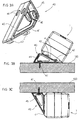
- Figure 3 shows two brackets 40 adapted to be fitted into the seats 20 of the base 4 of the socket outlet, to fix the socket outlet to a surface.
- the fixing bracket 40 is shaped substantially like a triangular frame.
- Two slot-type holes 44 are formed on the hypotenuse 43 of the triangular frame 40, to receive screw means for fixing of the bracket 40 to a surface, such as a table.
- the larger cathetus 41 of the triangular frame 40 is inclined with respect to the hypotenuse 43 by about 30°.
- two protruding hooks 42 are provided in asymmetrical positions on the larger cathetus 41 designed to engage, in a close-fitting relationship, in one of the two side openings 23 and in the central opening 22 of the seat 20, respectively. In this manner, the bracket 40 is integrally secured to the socket outlet 1.
- Two slots 46 are formed on the smaller cathetus 45 to receive screw means for fixing to a flat surface.
- Figure 3B illustrates fixing of the socket outlet 1 on top of a table 100.
- the hooks 42 of the bracket 40 are fitted into the respective openings 22 and 23 of the base 4 of the socket outlet 1 so as to support it.
- Screws 47 are inserted in the slot-type holes 44 of the larger cathetus 43 of the bracket 40 and fixed to the surface of the table 100. In this manner the socket outlet 1 is fixed on top of the table 100 and its bottom surface 4 is inclined by about 30° with respect to the surface of the table 100.
- FIG. 3C illustrates fixing of the socket outlet 1 beneath the surface of a table 100.
- the hooks of the brackets 40 are fixed to the socket outlet 1.
- the screws 47 are inserted in slot-type holes 46 provided in the smaller cathetus 45 of the bracket 40 and fixed to the surface of the table 100.
- the socket outlet 1 is fixed beneath the table 100 and its base surface 4 is inclined by about 90° with respect to the surface of the table 100.
- the side edges of the side openings 23, instead of being open, can be closed; what is important is that the side openings 23 allow the hooks 42 of the brackets 40 to be inserted.
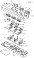
- the body 2 of the socket outlet 1 comprises an upper shell half 25 and a lower shell half 26 within which are contained nine blocks corresponding to switch devices of electrical socket outlets: six side blocks 50 and three central blocks 60.
- Three side blocks 50 are positioned on a side wall of the body 2 of the socket outlet between the upper shell half 25 and the lower shell half 26, another three side blocks 50 are positioned on the other side wall of the body of the socket outlet between the upper shell half 25 and the lower shell half 26 and the three central blocks 60 are positioned beneath the three circular seats 5 provided in the upper surface of the upper shell half 25.
- the six side blocks 50 have three holes, two of which are slot-shaped side holes 51 and one is a circular central hole 52. In this manner, the side blocks 50 can allow insertion of straight plugs with cylindrical pins of different diameters and centre distances, according to Italian standards.
- the central blocks 60 have three circular holes, two of which are side holes 61 and one a central hole 62.
- the holes 61 and 62 of the central blocks 60 are designed to be put in register with the respective holes provided in the seats 5 of the upper half shell 25.
- Each electrical contact assembly 70 comprises two lateral slot-shaped contacts 71 disposed facing each other on two opposite sides and a central slot-type contact 72 facing upward.
- the six slot-type side contacts 71 on the first side of the socket outlet correspond with the six side holes 51 of the three side blocks 50 on the first side of the socket outlet
- the six slot-type side contacts 71 on the second side of the of the socket outlet correspond to the six side holes 51 of the other three side blocks 50 on the second side of the socket
- the six central upward facing slot-type contacts 72 correspond to the six side holes 61 of the three central blocks 60.
- each arm of the E supports a respective contact assembly 80.
- the contact assembly 80 comprises two side contacts with respective holes 81 which face opposite sides, a central contact 82 comprising two tongues which define a central slot 83 and two tongues 7 which protrude upward from the side contacts to extend from the seats 5 so as to obtain the resilient contacts previously described.
- the holes 81 of the side contacts correspond with the central holes 52 of the side blocks and the central slots 83 of the central contacts 82 will correspond with the central holes 62 of the central blocks.
- the side bars 69 and the central bar 79 are mounted in special seats formed by means of walls disposed like a maze in the inner part of the lower shell half 26.
Landscapes
- Connector Housings Or Holding Contact Members (AREA)
- Coupling Device And Connection With Printed Circuit (AREA)
- Connecting Device With Holders (AREA)
- Control Of Motors That Do Not Use Commutators (AREA)
- Motorcycle And Bicycle Frame (AREA)
Applications Claiming Priority (2)
| Application Number | Priority Date | Filing Date | Title |
|---|---|---|---|
| IT2000MI000706U IT250397Y1 (it) | 2000-12-19 | 2000-12-19 | Presa di corrente mobile multipla |
| ITMI000706 | 2000-12-19 |
Publications (2)
| Publication Number | Publication Date |
|---|---|
| EP1217698A1 true EP1217698A1 (de) | 2002-06-26 |
| EP1217698B1 EP1217698B1 (de) | 2008-01-09 |
Family
ID=11444736
Family Applications (1)
| Application Number | Title | Priority Date | Filing Date |
|---|---|---|---|
| EP01130044A Expired - Lifetime EP1217698B1 (de) | 2000-12-19 | 2001-12-18 | Tragbare Mehrfachsteckdose |
Country Status (6)
| Country | Link |
|---|---|
| EP (1) | EP1217698B1 (de) |
| AT (1) | ATE383668T1 (de) |
| DE (1) | DE60132294T2 (de) |
| ES (1) | ES2295101T3 (de) |
| IT (1) | IT250397Y1 (de) |
| PT (1) | PT1217698E (de) |
Cited By (1)
| Publication number | Priority date | Publication date | Assignee | Title |
|---|---|---|---|---|
| EP1705758A1 (de) * | 2005-03-24 | 2006-09-27 | Zweibrüder Optoelectronics GmbH | Steckdosenleiste |
Families Citing this family (1)
| Publication number | Priority date | Publication date | Assignee | Title |
|---|---|---|---|---|
| DE102011050845B3 (de) * | 2011-06-06 | 2012-10-04 | Berker Gmbh & Co. Kg | Verfahren zur Herstellung eines Schutzkontaktbügels für eine Schutzkontaktsteckdose sowie eine Schutzkontaktsteckdose damit |
Citations (5)
| Publication number | Priority date | Publication date | Assignee | Title |
|---|---|---|---|---|
| US4705342A (en) * | 1985-11-12 | 1987-11-10 | Cable Electric Products, Inc. | Electrical extension outlet |
| US4830626A (en) * | 1988-07-27 | 1989-05-16 | Liu Tzu Chen | Christmas-tree securable extension cord |
| EP0411216A1 (de) * | 1989-08-01 | 1991-02-06 | Lee, Chiu-shan | Mehrzwecksicherheitssteckdose |
| DE29603529U1 (de) * | 1996-02-27 | 1996-06-13 | Schmid, Bernhard, 93161 Sinzing | Adapter zur Netzspannungsversorgung von Zusatzgeräten wie Drucker, Modem usw. über das PC-Netzteil |
| WO2000028628A1 (en) * | 1998-11-11 | 2000-05-18 | Curtis Computer Products | Multi-function outlet strip having cable organizing features |
-
2000
- 2000-12-19 IT IT2000MI000706U patent/IT250397Y1/it active
-
2001
- 2001-12-18 DE DE60132294T patent/DE60132294T2/de not_active Expired - Lifetime
- 2001-12-18 EP EP01130044A patent/EP1217698B1/de not_active Expired - Lifetime
- 2001-12-18 AT AT01130044T patent/ATE383668T1/de not_active IP Right Cessation
- 2001-12-18 PT PT01130044T patent/PT1217698E/pt unknown
- 2001-12-18 ES ES01130044T patent/ES2295101T3/es not_active Expired - Lifetime
Patent Citations (5)
| Publication number | Priority date | Publication date | Assignee | Title |
|---|---|---|---|---|
| US4705342A (en) * | 1985-11-12 | 1987-11-10 | Cable Electric Products, Inc. | Electrical extension outlet |
| US4830626A (en) * | 1988-07-27 | 1989-05-16 | Liu Tzu Chen | Christmas-tree securable extension cord |
| EP0411216A1 (de) * | 1989-08-01 | 1991-02-06 | Lee, Chiu-shan | Mehrzwecksicherheitssteckdose |
| DE29603529U1 (de) * | 1996-02-27 | 1996-06-13 | Schmid, Bernhard, 93161 Sinzing | Adapter zur Netzspannungsversorgung von Zusatzgeräten wie Drucker, Modem usw. über das PC-Netzteil |
| WO2000028628A1 (en) * | 1998-11-11 | 2000-05-18 | Curtis Computer Products | Multi-function outlet strip having cable organizing features |
Cited By (1)
| Publication number | Priority date | Publication date | Assignee | Title |
|---|---|---|---|---|
| EP1705758A1 (de) * | 2005-03-24 | 2006-09-27 | Zweibrüder Optoelectronics GmbH | Steckdosenleiste |
Also Published As
| Publication number | Publication date |
|---|---|
| ITMI20000706U1 (it) | 2002-06-19 |
| IT250397Y1 (it) | 2003-09-10 |
| ES2295101T3 (es) | 2008-04-16 |
| DE60132294T2 (de) | 2009-01-02 |
| ATE383668T1 (de) | 2008-01-15 |
| PT1217698E (pt) | 2008-03-27 |
| EP1217698B1 (de) | 2008-01-09 |
| DE60132294D1 (de) | 2008-02-21 |
Similar Documents
| Publication | Publication Date | Title |
|---|---|---|
| CA2018451C (en) | Multiple function electrical outlet and electrical distribution system utilizing the same | |
| US5650917A (en) | CPU card mounting structure | |
| US10243296B2 (en) | Safety socket with means to prevent electric shock and electrical discharge | |
| US7614922B1 (en) | Quick attachment junction box | |
| US9178324B2 (en) | Electric plug system | |
| KR920022617A (ko) | 전기 모우터 제어 부품용 장착장치 및 고정된 연결기 해제 방법 | |
| US4850882A (en) | Rotatably mounted printed circuit board test support and connector | |
| US8622758B2 (en) | Rotatable plug and power supply device having the rotatable plug | |
| US9666980B2 (en) | Electrical power strip housing | |
| KR940022949A (ko) | 공통 전기 커넥터 | |
| EP1217698B1 (de) | Tragbare Mehrfachsteckdose | |
| ES2928820T3 (es) | Contactor | |
| CA2506864C (en) | Receptacle retainer for snap-in style receptacles | |
| CA2314645A1 (en) | Christmas lamp base | |
| USD452486S1 (en) | DIN clip for housing unit | |
| CN223809365U (zh) | 电源线收纳座及电器 | |
| KR200229457Y1 (ko) | 책상용 배선 안내구조 | |
| KR19980064540U (ko) | 안전 플러그 소켓 | |
| KR200181494Y1 (ko) | 전력분배용 단자 고정대 | |
| PL208867B1 (pl) | Zespół łączeniowy gniazda wtyczkowego ściennego | |
| US2194905A (en) | Electric light fixture | |
| JPS6327373Y2 (de) | ||
| JP2562705Y2 (ja) | コードレステレホン用の収容装置 | |
| JPS6039992Y2 (ja) | 電気機器の取付装置 | |
| US3462725A (en) | Socket for spaced contacts of tubular members |
Legal Events
| Date | Code | Title | Description |
|---|---|---|---|
| PUAI | Public reference made under article 153(3) epc to a published international application that has entered the european phase |
Free format text: ORIGINAL CODE: 0009012 |
|
| AK | Designated contracting states |
Kind code of ref document: A1 Designated state(s): AT BE CH CY DE DK ES FI FR GB GR IE IT LI LU MC NL PT SE TR |
|
| AX | Request for extension of the european patent |
Free format text: AL;LT;LV;MK;RO;SI |
|
| 17P | Request for examination filed |
Effective date: 20021202 |
|
| AKX | Designation fees paid |
Designated state(s): AT BE CH CY DE DK ES FI FR GB GR IE IT LI LU MC NL PT SE TR |
|
| 17Q | First examination report despatched |
Effective date: 20070404 |
|
| RTI1 | Title (correction) |
Free format text: PORTABLE MULTIPLE ELECTRIC SOCKET OUTLET |
|
| GRAP | Despatch of communication of intention to grant a patent |
Free format text: ORIGINAL CODE: EPIDOSNIGR1 |
|
| GRAS | Grant fee paid |
Free format text: ORIGINAL CODE: EPIDOSNIGR3 |
|
| GRAA | (expected) grant |
Free format text: ORIGINAL CODE: 0009210 |
|
| AK | Designated contracting states |
Kind code of ref document: B1 Designated state(s): AT BE CH CY DE DK ES FI FR GB GR IE IT LI LU MC NL PT SE TR |
|
| REG | Reference to a national code |
Ref country code: GB Ref legal event code: FG4D |
|
| REG | Reference to a national code |
Ref country code: CH Ref legal event code: EP |
|
| REG | Reference to a national code |
Ref country code: IE Ref legal event code: FG4D |
|
| REG | Reference to a national code |
Ref country code: CH Ref legal event code: NV Representative=s name: A. BRAUN, BRAUN, HERITIER, ESCHMANN AG PATENTANWAE |
|
| REF | Corresponds to: |
Ref document number: 60132294 Country of ref document: DE Date of ref document: 20080221 Kind code of ref document: P |
|
| REG | Reference to a national code |
Ref country code: PT Ref legal event code: SC4A Free format text: AVAILABILITY OF NATIONAL TRANSLATION Effective date: 20080313 |
|
| REG | Reference to a national code |
Ref country code: ES Ref legal event code: FG2A Ref document number: 2295101 Country of ref document: ES Kind code of ref document: T3 |
|
| REG | Reference to a national code |
Ref country code: GR Ref legal event code: EP Ref document number: 20080400941 Country of ref document: GR |
|
| PG25 | Lapsed in a contracting state [announced via postgrant information from national office to epo] |
Ref country code: NL Free format text: LAPSE BECAUSE OF FAILURE TO SUBMIT A TRANSLATION OF THE DESCRIPTION OR TO PAY THE FEE WITHIN THE PRESCRIBED TIME-LIMIT Effective date: 20080109 |
|
| REG | Reference to a national code |
Ref country code: CH Ref legal event code: PFA Owner name: VIMAR SPA Free format text: VIMAR SPA#VIALE VICENZA 14#36063 MAROSTICA (VI) (IT) -TRANSFER TO- VIMAR SPA#VIALE VICENZA 14#36063 MAROSTICA (VI) (IT) |
|
| NLV1 | Nl: lapsed or annulled due to failure to fulfill the requirements of art. 29p and 29m of the patents act | ||
| PG25 | Lapsed in a contracting state [announced via postgrant information from national office to epo] |
Ref country code: FI Free format text: LAPSE BECAUSE OF FAILURE TO SUBMIT A TRANSLATION OF THE DESCRIPTION OR TO PAY THE FEE WITHIN THE PRESCRIBED TIME-LIMIT Effective date: 20080109 |
|
| ET | Fr: translation filed | ||
| PG25 | Lapsed in a contracting state [announced via postgrant information from national office to epo] |
Ref country code: DK Free format text: LAPSE BECAUSE OF FAILURE TO SUBMIT A TRANSLATION OF THE DESCRIPTION OR TO PAY THE FEE WITHIN THE PRESCRIBED TIME-LIMIT Effective date: 20080109 Ref country code: SE Free format text: LAPSE BECAUSE OF FAILURE TO SUBMIT A TRANSLATION OF THE DESCRIPTION OR TO PAY THE FEE WITHIN THE PRESCRIBED TIME-LIMIT Effective date: 20080409 |
|
| PLBE | No opposition filed within time limit |
Free format text: ORIGINAL CODE: 0009261 |
|
| STAA | Information on the status of an ep patent application or granted ep patent |
Free format text: STATUS: NO OPPOSITION FILED WITHIN TIME LIMIT |
|
| 26N | No opposition filed |
Effective date: 20081010 |
|
| PG25 | Lapsed in a contracting state [announced via postgrant information from national office to epo] |
Ref country code: MC Free format text: LAPSE BECAUSE OF NON-PAYMENT OF DUE FEES Effective date: 20081231 Ref country code: CY Free format text: LAPSE BECAUSE OF FAILURE TO SUBMIT A TRANSLATION OF THE DESCRIPTION OR TO PAY THE FEE WITHIN THE PRESCRIBED TIME-LIMIT Effective date: 20080109 |
|
| GBPC | Gb: european patent ceased through non-payment of renewal fee |
Effective date: 20081218 |
|
| PG25 | Lapsed in a contracting state [announced via postgrant information from national office to epo] |
Ref country code: GB Free format text: LAPSE BECAUSE OF NON-PAYMENT OF DUE FEES Effective date: 20081218 |
|
| PGFP | Annual fee paid to national office [announced via postgrant information from national office to epo] |
Ref country code: AT Payment date: 20091223 Year of fee payment: 9 Ref country code: CH Payment date: 20091124 Year of fee payment: 9 Ref country code: IE Payment date: 20091211 Year of fee payment: 9 Ref country code: LU Payment date: 20091230 Year of fee payment: 9 Ref country code: TR Payment date: 20091218 Year of fee payment: 9 |
|
| PGFP | Annual fee paid to national office [announced via postgrant information from national office to epo] |
Ref country code: PT Payment date: 20091124 Year of fee payment: 9 |
|
| PGFP | Annual fee paid to national office [announced via postgrant information from national office to epo] |
Ref country code: ES Payment date: 20091230 Year of fee payment: 9 Ref country code: FR Payment date: 20091217 Year of fee payment: 9 |
|
| PGFP | Annual fee paid to national office [announced via postgrant information from national office to epo] |
Ref country code: BE Payment date: 20091221 Year of fee payment: 9 Ref country code: DE Payment date: 20091230 Year of fee payment: 9 Ref country code: GR Payment date: 20091130 Year of fee payment: 9 |
|
| REG | Reference to a national code |
Ref country code: PT Ref legal event code: MM4A Free format text: LAPSE DUE TO NON-PAYMENT OF FEES Effective date: 20110620 |
|
| BERE | Be: lapsed |
Owner name: VIMAR S.P.A. Effective date: 20101231 |
|
| PG25 | Lapsed in a contracting state [announced via postgrant information from national office to epo] |
Ref country code: PT Free format text: LAPSE BECAUSE OF NON-PAYMENT OF DUE FEES Effective date: 20110620 |
|
| REG | Reference to a national code |
Ref country code: CH Ref legal event code: PL |
|
| PG25 | Lapsed in a contracting state [announced via postgrant information from national office to epo] |
Ref country code: AT Free format text: LAPSE BECAUSE OF NON-PAYMENT OF DUE FEES Effective date: 20101218 |
|
| REG | Reference to a national code |
Ref country code: FR Ref legal event code: ST Effective date: 20110831 |
|
| PG25 | Lapsed in a contracting state [announced via postgrant information from national office to epo] |
Ref country code: BE Free format text: LAPSE BECAUSE OF NON-PAYMENT OF DUE FEES Effective date: 20101231 |
|
| PG25 | Lapsed in a contracting state [announced via postgrant information from national office to epo] |
Ref country code: IE Free format text: LAPSE BECAUSE OF NON-PAYMENT OF DUE FEES Effective date: 20101220 Ref country code: FR Free format text: LAPSE BECAUSE OF NON-PAYMENT OF DUE FEES Effective date: 20110103 Ref country code: CH Free format text: LAPSE BECAUSE OF NON-PAYMENT OF DUE FEES Effective date: 20101231 Ref country code: LI Free format text: LAPSE BECAUSE OF NON-PAYMENT OF DUE FEES Effective date: 20101231 |
|
| REG | Reference to a national code |
Ref country code: DE Ref legal event code: R119 Ref document number: 60132294 Country of ref document: DE Effective date: 20110701 |
|
| PG25 | Lapsed in a contracting state [announced via postgrant information from national office to epo] |
Ref country code: DE Free format text: LAPSE BECAUSE OF NON-PAYMENT OF DUE FEES Effective date: 20110701 Ref country code: GR Free format text: LAPSE BECAUSE OF NON-PAYMENT OF DUE FEES Effective date: 20110704 |
|
| REG | Reference to a national code |
Ref country code: ES Ref legal event code: FD2A Effective date: 20120305 |
|
| PG25 | Lapsed in a contracting state [announced via postgrant information from national office to epo] |
Ref country code: ES Free format text: LAPSE BECAUSE OF NON-PAYMENT OF DUE FEES Effective date: 20101219 |
|
| PG25 | Lapsed in a contracting state [announced via postgrant information from national office to epo] |
Ref country code: LU Free format text: LAPSE BECAUSE OF NON-PAYMENT OF DUE FEES Effective date: 20101218 |
|
| PG25 | Lapsed in a contracting state [announced via postgrant information from national office to epo] |
Ref country code: TR Free format text: LAPSE BECAUSE OF NON-PAYMENT OF DUE FEES Effective date: 20101218 |
|
| PGFP | Annual fee paid to national office [announced via postgrant information from national office to epo] |
Ref country code: IT Payment date: 20121221 Year of fee payment: 12 |
|
| PG25 | Lapsed in a contracting state [announced via postgrant information from national office to epo] |
Ref country code: IT Free format text: LAPSE BECAUSE OF NON-PAYMENT OF DUE FEES Effective date: 20131231 |
|
| PG25 | Lapsed in a contracting state [announced via postgrant information from national office to epo] |
Ref country code: IT Free format text: LAPSE BECAUSE OF NON-PAYMENT OF DUE FEES Effective date: 20131218 |