EP1217748A2 - Décodeur en bande pour correcteur d'erreur sans voie de retour (FEC) pour SONET - Google Patents
Décodeur en bande pour correcteur d'erreur sans voie de retour (FEC) pour SONET Download PDFInfo
- Publication number
- EP1217748A2 EP1217748A2 EP01128376A EP01128376A EP1217748A2 EP 1217748 A2 EP1217748 A2 EP 1217748A2 EP 01128376 A EP01128376 A EP 01128376A EP 01128376 A EP01128376 A EP 01128376A EP 1217748 A2 EP1217748 A2 EP 1217748A2
- Authority
- EP
- European Patent Office
- Prior art keywords
- specified
- block
- fec decoder
- data
- error
- Prior art date
- Legal status (The legal status is an assumption and is not a legal conclusion. Google has not performed a legal analysis and makes no representation as to the accuracy of the status listed.)
- Withdrawn
Links
- RGNPBRKPHBKNKX-UHFFFAOYSA-N hexaflumuron Chemical compound C1=C(Cl)C(OC(F)(F)C(F)F)=C(Cl)C=C1NC(=O)NC(=O)C1=C(F)C=CC=C1F RGNPBRKPHBKNKX-UHFFFAOYSA-N 0.000 title abstract description 17
- 208000011580 syndromic disease Diseases 0.000 claims abstract description 59
- 238000012937 correction Methods 0.000 claims abstract description 37
- 238000004364 calculation method Methods 0.000 claims description 36
- 238000000034 method Methods 0.000 claims description 22
- 102100037651 AP-2 complex subunit sigma Human genes 0.000 abstract description 8
- 101000806914 Homo sapiens AP-2 complex subunit sigma Proteins 0.000 abstract description 8
- 230000008901 benefit Effects 0.000 abstract description 4
- 238000010586 diagram Methods 0.000 description 18
- 239000013598 vector Substances 0.000 description 15
- 238000013461 design Methods 0.000 description 5
- 238000003780 insertion Methods 0.000 description 5
- 230000037431 insertion Effects 0.000 description 5
- 238000001514 detection method Methods 0.000 description 4
- JSZZRFHXEQCEJM-UHFFFAOYSA-N 7-hydroxy-10,10-dimethyl-7-phenylpyrido[1,2-a]indole-6,8-dione Chemical compound O=C1N2C3=CC=CC=C3C(C)(C)C2=CC(=O)C1(O)C1=CC=CC=C1 JSZZRFHXEQCEJM-UHFFFAOYSA-N 0.000 description 2
- 230000005540 biological transmission Effects 0.000 description 2
- 230000003111 delayed effect Effects 0.000 description 2
- 238000012986 modification Methods 0.000 description 2
- 230000004048 modification Effects 0.000 description 2
- 230000008569 process Effects 0.000 description 2
- 238000012360 testing method Methods 0.000 description 2
- 230000004913 activation Effects 0.000 description 1
- 238000013459 approach Methods 0.000 description 1
- 238000004891 communication Methods 0.000 description 1
- 125000004122 cyclic group Chemical group 0.000 description 1
- 238000013500 data storage Methods 0.000 description 1
- 230000009849 deactivation Effects 0.000 description 1
- 239000000835 fiber Substances 0.000 description 1
- 230000010354 integration Effects 0.000 description 1
- 230000003993 interaction Effects 0.000 description 1
- 238000012544 monitoring process Methods 0.000 description 1
- 230000003287 optical effect Effects 0.000 description 1
Images


Classifications
-
- H—ELECTRICITY
- H04—ELECTRIC COMMUNICATION TECHNIQUE
- H04J—MULTIPLEX COMMUNICATION
- H04J3/00—Time-division multiplex systems
- H04J3/16—Time-division multiplex systems in which the time allocation to individual channels within a transmission cycle is variable, e.g. to accommodate varying complexity of signals, to vary number of channels transmitted
- H04J3/1605—Fixed allocated frame structures
- H04J3/1611—Synchronous digital hierarchy [SDH] or SONET
-
- H—ELECTRICITY
- H04—ELECTRIC COMMUNICATION TECHNIQUE
- H04L—TRANSMISSION OF DIGITAL INFORMATION, e.g. TELEGRAPHIC COMMUNICATION
- H04L1/00—Arrangements for detecting or preventing errors in the information received
- H04L1/004—Arrangements for detecting or preventing errors in the information received by using forward error control
- H04L1/0045—Arrangements at the receiver end
-
- H—ELECTRICITY
- H04—ELECTRIC COMMUNICATION TECHNIQUE
- H04L—TRANSMISSION OF DIGITAL INFORMATION, e.g. TELEGRAPHIC COMMUNICATION
- H04L1/00—Arrangements for detecting or preventing errors in the information received
- H04L1/004—Arrangements for detecting or preventing errors in the information received by using forward error control
- H04L1/0056—Systems characterized by the type of code used
- H04L1/0057—Block codes
Definitions
- the present invention is related to optical communication systems, and more particularly to forward error correction (FEC) functions in those networks.
- FEC forward error correction
- the scope of the SONET Standard is for OC-48 and OC-192.
- Conforming circuitry should also be able to detect uncorrectable error conditions (i.e., when there is more than 3 errors per row per bit-slice).
- the FEC layer falls below the line layer and provides a "correction service" to the line layer.
- circuitry and methodology applicable for both SONET and SDH that meets the requirements of these proposed Standards and that gives optimal performance in terms of circuitry area and time to do the encoding and decoding.
- the circuitry and methodology should be operable in OC-48 and OC-192 data rates and disable OC-12 data, should also meet the latency requirements of the Standards, and may preferably be used for higher data rates.
- the present invention achieves technical advantages as a FEC decoder.
- the FEC decoder is made up of a top level controller and individual FEC bit decoders.
- the top level controller has a state machine for the decoder, and sends out enable signals to the individual bit decoders.
- the total delay through the decoding system is only about 14.6 microseconds.
- Each bit decoder preferably includes a main controller, 3 syndrome generator blocks, a controller for syndrome checkers, 3 syndrome checking blocks, a block to calculate sigma 2, a block to calculate sigma 3, a Chien search block, a storage block, an error correction block, an error counting block, a data selection block, and a decoder status block.
- the blocks meet all the requirements of both the SDH Standard and the SONET Standard T1 x 1.5/99-R218R3 and operates with both OC-48 and OC-192 data.
- the shortened BCH code is derived from a (8191, 8152) parent code.
- the block size is 1 row (bit-slice) of STS-48 (4320 information bits plus 39 check bits per block).
- the Chien search is used.
- the Chien search steps sequentially through all possible error-locator values and corrects the corresponding bits as the locators are found.
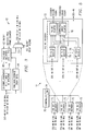
- System 10 is seen to include an FEC encoder 12, and FEC decoder 11.
- the encoder 12 further includes a checkbit generator 14 and a linear feedback shift registers (LFSR) G(x) 16.
- the decoder 11 is seen to include syndrome generator 20, sigma calculation 22, and error correction circuit 24. Further provided is an uncorrectable error detection circuit 26.
- Syndrome generator 20 is seen to further include three LFSR's used in the FEC decoding, shown at 27, 28 and 30.
- a multiplier 32 and a squarer 34 are seen to be utilized by both the sigma calculation 22 and the error correction circuit 24.
- the error correction circuit 24 is seen to include four_increment by 4 LFSRs 36 and a serial LFSR shown at 38.
- the circuitry of the present invention 10 operates 4-bit parallel circuits at 78 Mhz.
- the encoder 12 circuit reduces the latency of the system 10 and fits into a typical STS-48 and STS-192 SONET receiver/transmitter system.
- serial circuitry that complements the parallel circuitry to do the encoding and decoding is utilized.
- the present invention has many advantages over the prior art. For instance, the decoding circuits in FEC decoder 14 use discrete mathematical units for GF(2 m ) computations instead of a ROM table as in the prior art.
- the mathematical units such as the squarer 34 and multiplier 32 compute in 1 clock cycle instead of many clock cycles. This speeds up the decoding and alleviates routing congestions.
- the blocks are partitioned to take advantage of the discrete mathematical circuitry and parallel circuitry to give low latency (or less delay).
- an STS-48 application such as shown in Figure 1A, 4 individual FEC encoding blocks and 4 FEC decoding blocks are used that process each bit of the byte.
- the blocks operate in parallel and have their own controller and frame counter. This provides up to 24 burst error correction per STS-48 row.
- another top level control block per STS-48 is provided.
- the FEC encoder 12 is made up of individual bit FEC encoders 40.
- the design of each bit encoder 40 is the same.
- the encoder 40 consists of 8 bit slice encoders as shown at 42.
- each bit-slice encoder 42 is comprised of a checkbit generator 44, an over-head insertion circuit 46, a row data storage 48, and an FEC on/off delay circuit 50.
- each bit-slice encoder 42 is further illustrated to consist of a controller block 52, having a controller state machine block 54, the checkbit generator block 44, a FEC Status indication (FSI) bit insertion block 55, 2 different blocks to insert in checkbits 58, and a selection block 60. These blocks implement and meet the requirements of the Standard.
- the total delay through the encoding system 12 is about 14 microseconds.
- the controller 52 sends out signals to the checkbit generation 44 to shift in information bits, shift in zeros, shift out checkbits, and disable encoding of certain bits.
- the controller 52 also sends out the frame counter signals and end of row markers.
- the checkbit generator 44 generates the checkbits to be inserted in the section overhead (SOH) and line overhead (LOH).
- the 2 different insertion blocks 58 insert checkbits with minimum delay and minimum checkbit storage.
- a 1104x4 RAM 59 is used by the 2 nd checkbit insertion block to delay data.
- the controller state machine 54 implements the state machine requirements in the Standard.
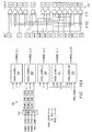
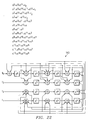
- the FEC decoder 11 is made up of a top level controller 70 and individual FEC bit decoders 72.
- Top level controller 70 has a state machine 74 for controlling the decoders 72 for sending the enable signals to the individual bit decoders 72.
- the total delay through the decoding system 14 is about 14.6 microseconds.
- each bit-sliced decoder 78 has a main controller 76, 3 syndrome generator blocks 79, for 3 syndrome checking blocks 80, a block 82 to calculate sigma 2, a block 84 to calculate sigma 3, a Chien search block 86, a counter 87, a storage block (1152x4 RAM) 88, an error correction block 90, an error counting block 92, a data selection block 94, and a decoder status block 96.
- the main controller 76 sends out the signals to enable/disable the functions of the other blocks, except syndrome checking blocks 80.
- a controller 79 for syndrome checking blocks 80 generates the signals specific to enabling/disabling the syndrome checking functions 80.
- the syndrome generators 78 send the syndromes to the sigma calculation blocks 82 & 84, which contains discrete multiply, squaring, adding circuitry.
- the sigma results are sent to the Chien search 86, where it finds the roots of the error polynomial.
- the Chien search block 86 sends the error ID locations to the error correction block 90, which corrects both the delayed information and the checkbit errors (up to 3 errors).
- the error count block 92 counts the number of errors corrected by error correction block 90.
- the corrected information and check bits are sent to the syndrome checking blocks 80 to detect uncorrectable error conditions.
- the decode status block 96 will inform the upper level of this condition. There may be cases where the information is so errored that it is undetectable by even the syndrome checkers 80. It would be up to the B2 calculation to detect these errors, as shown in Figure 1A.
- the checkbit generator 14 implements the equation for R(X) from the Standard.
- G(X) G1(x)*G3(x)*G5(x).
- Checkbit generator 14 is shown in more detail in Figure 8 and Figure 9.
- Checkbit generator 14 is composed of LFSR's 100 & 102. Each LFSR can operate in both 4-bit parallel and 1 bit serial 39 bit modes.
- the LFSRs 100 and 102 work together to allow data to continuously be shifted in and checkbits to be generated.
- the first LFSR 100 shifts in the information bits.
- the first LFSR 100 dumps its contents to the second LFSR 102, which immediately shifts in 39 zero-bits and does the modulus operation.
- the contents in the second LFSR 102 contains the 39 checkbits once the zero bits have been shifted in. Then, the checkbits are shifted out 4 bits at a time to checkbit register 104, which feeds a checkbit insertion block 106.
- the serial circuitry for the LFSRs 100 and 102 are derived by multiplying and reducing the 3 smaller polynomial functions using GF(2 13 ) and modulus 2 mathematics.
- the parallel circuitry for the LFSRs 100 and 102 are functionally identical to the serial implementation.
- the timing for the signals of the checkbit generator 14 are depicted in Figure 9.
- the LFSRs that perform these functions are Generators 44. Controller 52 generates these signals including SHIFT_12_ZERO for the encoder.
- the syndrome generators 26, 28 and 30 are made up of 3 blocks that calculate Syndrome 1(S1), Syndrome 3 (S3), and Syndrome 5 (S5).
- Each block is composed of two linear feedback shift registers (LFSR) 110 and 112.
- LFSR linear feedback shift registers
- Each LFSR 110 and 112 can operate in both 4-bit parallel and 1-bit serial 39 bit modes.
- the 2 LFSRs 110 and 112 work together to allow data to continuously be shifted in and a syndrome to be generated.
- the first LFSR 110 shifts in the information bits. At the end of each row, after the information bits have been shifted in, the first LFSR 110 dumps its contents to the second LFSR 112, which shifts in the 39 checkbits which does the modulus operation.
- the contents in the second LFSR 112 contains the syndrome once the checkbits have been shifted in. Then, the checkbits are shifted out 4 bits at a time.
- the sigma calculation for FEC decoding of the BCH-3 code is done with discrete mathematics units and uses parallel structure to accomplish the computation with low latency.
- ⁇ 3 (S 1 3 + S 3 ) + S 1 ⁇ 2
- the present invention implements a custom multiplier and squarer to do multiplication, squaring, and cubing as shown in more detail in Figure 16, 17 and 18.
- the cubing is done by multiplying the output of the squarer and one of it's inputs.
- the addition is done using XOR gates.
- the division circuit is based on the circuit proposed in Yuh-Tsuen Horng and Shyue-Win Wei, "Fast Inverters and Dividers for Finite Field GF(2 m )", 1994 IEEE, the teachings of which are incorporated herein by reference.
- the sigma2 and sigma3 computation circuit 22 is also seen to include an S1 cuber circuit 124.
- the S1*S3 multiplier 122 provides a product output to the S5 adder circuit 126, and the S1 cuber circuit 124 outputs its cubed output to a S3 adder circuit 130.
- the S1 cuber circuit 124 is made up of a multiplier that takes its inputs and the result of the squarer circuit 120 receiving sigma 1.
- the adders 126 and 130 provide their outputs to a sigma 2 divider circuit 132, as shown.
- the squarer 120 takes 2 inputs to be multiplied and outputs the results in 1 clock cycle. This solution is custom for GF(2 13 ). For other powers, the same methodology can be implemented, but the resulting gates will be different. Refer to Figures 17 & 18 for detailed depictions of the Squarer circuit, the Multiplier circuit and the Cuber circuit.
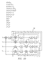
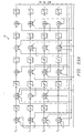
- the present invention uses parallel Chien search blocks to search roots 4 bits at a time as shown at 140.
- This parallel scheme reduces latency and meets the 4-bit 78Mhz data rate used.
- the serial Chien search corrects the checkbits errors.
- the Chien search block implements the following equations.
- Circuit 140 is seen to include a sigma synchronizer circuit 142 having 3 outputs identified as sigma 1 sync, sigma 2 sync, and sigma 3 sync, which outputs are provided to a plurality of Chien search circuits shown at 146.
- Each Chien search circuit 146 provides a respective output shown as error ID.
- CHIEN_SEARCH_1 block 146, CHIEN_SEARCH_2 block 147, CHIEN_SEARCH_3 block 149, and CHIEN_SEARCH_4 block 151 generate Error Ids for both information bit errors and certain checkbit errors (checkbits for rows 3,5,6,7,8, and 9).
- CHIEN_SEARCH_1 block 146 corrects errors in bit position 3 of the data.
- CHIEN_SEARCH_2 147 corrects errors in bit position 2 of the data.
- CHIEN_SEARCH_3 block 149 corrects errors in bit position 1 of the data.
- CHIEN_SEARCH_4 block 151 corrects errors in bit position 0 of the data.
- Block 200 generates the Galois Field vectors (for information bits and checkbits).
- POWER_GEN1 block 200 generates the Galois field vectors for the information bits locations and for the checkbit locations for rows 3,5,6,7,8, and 9 to send to the mathematical units SQUARER block 204, CUBER block 206, SIGMA1_MULT block 210, SIGMA2_MULT block 212, and SIGMA3_MULT block 214.
- the results from sigma multiplier blocks 210, 212, and 214 are sent to the ADD_COMPARE block 216 which generates the error_id.
- the CUBER block 206 is made up of a multiplier block that takes in the squared result from the SQUARER block 204.
- the mathematical units block 204,206,210,212,214, and 216 implement the Chien Search equation Eq. 2.7.
- the lower hierarchy of each of CHIEN_SEARCH_2 block 147, CHIEN_SEARCH_3 block 149, and CHIEN_SEARCH_4 block 151 are all similar to CHIEN_SEARCH_1 146 shown in Figure 16B, except they generate different vector locations pertaining to their specific bit position in the data.
- the error ids generated are used by the error correction block 90 to correct the delayed data as they are shifted through the 1152x4 RAM 88.
- Figure 16C shows the lower hierarchy of the CHIEN_SEARCH_CB block 153 which generates Error Ids for all checkbit errors.
- a POWER_GEN_CB block 218 that generates serial Galois Field vectors.
- a SQUARER block 220, a CUBER block 222, a MULTIPLIER block 226, 228, 230, and an ADD_COMPARE block 216 implements the Chien Search equation for each Galois Field vector generated that tests the location for the error roots.
- the CUBER block 222 is made up of a multiplier block that takes in the squared result from the SQUARER block 220.
- the Error Ids provided by CHIEN_SEARCH_CB block 153 are used to correct the stored checkbits for use in error correction failure detection syndrome checking blocks 80.
- the corrected stored checkbits for rows 1, 2, and 4 are inserted into the overhead as the data is shifted through 88.
- the "corrected" information bits and checkbits are fed into the parallel syndrome 80 generator to see if the syndromes are zero. If the syndromes are not zero, the error correction is declared a failure. This is a sure and simple method to determine if there are more than 3 errors (max number of errors correctable). Although this failure detection module 26 can't catch all cases of error correction failure, this approach is very reliable to predict when error correction has failed.
- the checking circuits 80 are the same circuits used for syndrome generator 79, so there is reuse and low latency associated with this method. If the number of total error ids ( both information and checkbits) are more than three for a particular row, an error correction failure is declared by checker 26 because there should be three or less error ids generated for a particular row.
- CHIEN_SEARCH_CB block 153 Since CHIEN_SEARCH_CB block 153 generates error_ids for all checkbits and the other CHIEN_SEARCHs blocks 146, 147, 149 and 151 generate error_ids for checkbits in rows 3,5,6,7,8, and 9. Error count Block 92 ensures that the checkbit error_ids aren't counted twice for the same row. Thus, only the error_ids generated by CHIEN_SEARCH_CB Block 153 are added to the other error_ids for rows 1,2, and 4.
- Each cell takes three 2 input AND, three 2-input XOR gates and four 1 bit latches.
- the GF(2 13 ) vectors are multiplied by a multiplier 122.
- the present invention has a multiplier 122 that takes 2 inputs to be multiplied and outputs the results multiplication in GF(2 13 ) in 1 clock cycle.
- the basic cell has two 2-input AND gates, two 2-input XOR gates, and three 1-bit latches.
- the multiplier can also have a 2 stage pipelined to meet more stringent timing requirements. It would take 2 clock cycles to complete 1 multiplication.
- the 1 st stage is TERMS(0-24) and the 2 nd stage is the RESULT_M(0-12).
- This LFSR implements the G1 (x) function according to Standard, and runs at 78 Mhz and has 4 bit-parallel inputs in the example.
- the circuit implements 4-bit parallel linear shift register (LFSR) for the circuits in the syndrome generators for implementing FEC according to the present invention.
- LFSR 4-bit parallel linear shift register
- This LFSR implements the G3 (x) function according to Standard, and runs at 78 Mhz and has 4 bit-parallel inputs.
- the circuit implements 4-bit parallel linear shift register (LFSR) for the circuits in the syndrome generators for implementing FEC according to the present invention.
- This LFSR implements the G5 (x) function according to Standard, and runs at 78 Mhz and has 4 bit-parallel inputs.
- the circuit implements 4-bit parallel linear shift register (LFSR) for the circuits in the checkbit generator for implementing FEC according to the present invention.
- LFSR 4-bit parallel linear shift register
- This LFSR implements the GX (x) function according to Standard, and runs at 78 Mhz and has 4 bit-parallel inputs.
- the circuit implements 4-bit parallel linear shift register (LFSR) for the circuits in the checkbit generator for implementing FEC according to the present invention.
- LFSR 4-bit parallel linear shift register
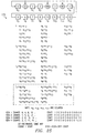
- the calculations for the 4-bit parallel LFSR is depicted in Figure 24.
- Galois Field generators there 4 Galois Field generators generally at 170. Since the FEC decoder 11 is operating at 78 Mhz in 4-bit parallel mode, the circuits generating 4 GF2 13 vectors and feeding the 4 Chien Search circuits (used in error correction) operate in parallel to search for the roots of the error polynomial.
- This circuit 170 is used to create the 4 vector generators that increment by 4 instead of incrementing by 1.
- This circuit 170 is a variant of the basic GF 2 13 vector generator that is made up of a linear feedback shift register. It increments by 4 instead of incrementing by 1.
- FIG. 26 there is shown at 180 a circuit to generate serial GF(2 13 ) vectors for the error correction of the checkbits.
- FEC activation and deactivation operational states are provided, along with FEC status indication FSI, line AIS interaction with FEC, and associated Figures and graphs.
- This Standard further provides clarity and integration of the present invention into the overall standard and which meets all requirements of this standard.
Landscapes
- Engineering & Computer Science (AREA)
- Computer Networks & Wireless Communication (AREA)
- Signal Processing (AREA)
- Error Detection And Correction (AREA)
Applications Claiming Priority (2)
| Application Number | Priority Date | Filing Date | Title |
|---|---|---|---|
| US738198 | 1985-05-24 | ||
| US09/738,198 US20020116679A1 (en) | 2000-12-15 | 2000-12-15 | In-band FEC decoder for sonet |
Publications (2)
| Publication Number | Publication Date |
|---|---|
| EP1217748A2 true EP1217748A2 (fr) | 2002-06-26 |
| EP1217748A3 EP1217748A3 (fr) | 2002-07-24 |
Family
ID=24966971
Family Applications (1)
| Application Number | Title | Priority Date | Filing Date |
|---|---|---|---|
| EP01128376A Withdrawn EP1217748A3 (fr) | 2000-12-15 | 2001-12-03 | Décodeur en bande pour correcteur d'erreur sans voie de retour (FEC) pour SONET |
Country Status (3)
| Country | Link |
|---|---|
| US (1) | US20020116679A1 (fr) |
| EP (1) | EP1217748A3 (fr) |
| CN (1) | CN1359203A (fr) |
Families Citing this family (9)
| Publication number | Priority date | Publication date | Assignee | Title |
|---|---|---|---|---|
| US7085282B2 (en) * | 2003-07-01 | 2006-08-01 | Thomson Licensing | Method and apparatus for providing forward error correction |
| CN100461662C (zh) * | 2005-07-18 | 2009-02-11 | Ut斯达康通讯有限公司 | 用于同步数字系列/同步光纤网系统的带内前向纠错解码器 |
| CN1968036B (zh) * | 2006-05-31 | 2010-04-07 | 华为技术有限公司 | 一种前向纠错解码装置及控制方法 |
| CN101330369B (zh) * | 2007-06-21 | 2014-07-09 | 华为技术有限公司 | 发送、接收方法及装置、通道保护方法及系统 |
| JP5810670B2 (ja) * | 2011-06-24 | 2015-11-11 | 富士通株式会社 | 誤り訂正処理回路および誤り訂正処理方法 |
| US9448959B2 (en) * | 2012-10-05 | 2016-09-20 | Analog Devices, Inc. | Two-wire communication protocol engine |
| JP2014082574A (ja) * | 2012-10-15 | 2014-05-08 | Samsung Electronics Co Ltd | 誤り検出訂正回路、及びメモリ装置 |
| GB2555459B (en) * | 2016-10-28 | 2018-10-31 | Imagination Tech Ltd | Division synthesis |
| EP3612939B1 (fr) * | 2017-04-17 | 2025-04-16 | Mobileye Vision Technologies Ltd. | Systèmes et procédés de correction d'erreurs |
Family Cites Families (15)
| Publication number | Priority date | Publication date | Assignee | Title |
|---|---|---|---|---|
| JPS6162234A (ja) * | 1984-09-04 | 1986-03-31 | Kokusai Denshin Denwa Co Ltd <Kdd> | 誤り訂正符号復号方式 |
| US4649541A (en) * | 1984-11-21 | 1987-03-10 | The United States Of America As Represented By The Administrator Of The National Aeronautics And Space Administration | Reed-Solomon decoder |
| JPH0728227B2 (ja) * | 1985-06-07 | 1995-03-29 | ソニー株式会社 | Bch符号の復号装置 |
| US5440570A (en) * | 1990-03-27 | 1995-08-08 | National Science Council | Real-time binary BCH decoder |
| US5323402A (en) * | 1991-02-14 | 1994-06-21 | The Mitre Corporation | Programmable systolic BCH decoder |
| JP2824474B2 (ja) * | 1992-02-17 | 1998-11-11 | 三菱電機株式会社 | 誤り訂正方式及びこの誤り訂正方式を用いた復号器 |
| US5912905A (en) * | 1994-03-25 | 1999-06-15 | Mitsubishi Denki Kabushiki Kaisha | Error-correcting encoder, error-correcting decoder and data transmitting system with error-correcting codes |
| US5574717A (en) * | 1994-05-17 | 1996-11-12 | Nippon Telegraph And Telephone Corporation | Line terminating equipment in SDH networks, using forward error correcting codes |
| JP3710198B2 (ja) * | 1996-04-18 | 2005-10-26 | 沖電気工業株式会社 | Stm−n信号の誤り訂正符号化・復号化方法、stm−n信号の誤り訂正符号化回路及びstm−n信号の誤り訂正復号化回路 |
| US6061826A (en) * | 1997-07-29 | 2000-05-09 | Philips Electronics North America Corp. | Hardware-optimized reed-solomon decoder for large data blocks |
| US6192497B1 (en) * | 1998-08-27 | 2001-02-20 | Adaptec, Inc. | Parallel Chien search circuit |
| US6279137B1 (en) * | 1998-12-08 | 2001-08-21 | Lsi Logic Corporation | System and method for a storage-efficient parallel Chien Search |
| EP1011202A3 (fr) * | 1998-12-11 | 2003-07-09 | Matsushita Electric Industrial Co., Ltd. | Décodeur Reed-Solomon |
| US6516436B1 (en) * | 1999-03-04 | 2003-02-04 | Lucent Technologies Inc. | Error control coding for transmission equipment protection |
| US6539515B1 (en) * | 1999-11-24 | 2003-03-25 | Koninklijke Philips Electronics N.V. | Accelerated Reed-Solomon error correction |
-
2000
- 2000-12-15 US US09/738,198 patent/US20020116679A1/en not_active Abandoned
-
2001
- 2001-12-03 EP EP01128376A patent/EP1217748A3/fr not_active Withdrawn
- 2001-12-14 CN CN01143830.4A patent/CN1359203A/zh active Pending
Non-Patent Citations (4)
| Title |
|---|
| BERLEKAMP E: "Algebraic Coding Theory" 1968 , ALGEBRAIC CODING THEORY, NEW YORK, MCGRAW-HILL, US, PAGE(S) 12-20 XP002132710 * page 12 - page 20 * * page 19 * * |
| BLAHUT R E: "THEORY AND PRACTICE OF ERROR CONTROL CODES. PASSAGE TEXT" , THEORY AND PRACTICE OF ERROR CONTROL CODES, READING, ADDISON WESLEY, US, PAGE(S) 166-183 XP002053992 * page 166 - page 183 * * |
| HASAN M A ET AL: "ALGORITHMS AND ARCHITECTURES FOR THE DESIGN OF A VLSI REED-SOLOMON CODEC" , REED-SOLOMON CODES AND THEIR APPLICATIONS, XX, XX, PAGE(S) 60-107 XP002055402 * paragraph [05.7]; figures 5-8 * * |
| K. AZADET AND M. YU: "Forward Error Correction (FEC) techniques for optical communications" IEEE 802.3 HIGH-SPEED STUDY GROUP, July 1999 (1999-07), pages 1-31, XP002200575 Montreal * |
Also Published As
| Publication number | Publication date |
|---|---|
| EP1217748A3 (fr) | 2002-07-24 |
| US20020116679A1 (en) | 2002-08-22 |
| CN1359203A (zh) | 2002-07-17 |
Similar Documents
| Publication | Publication Date | Title |
|---|---|---|
| Song et al. | 10-and 40-Gb/s forward error correction devices for optical communications | |
| US8055984B2 (en) | Forward error correction scheme compatible with the bit error spreading of a scrambler | |
| US7103830B1 (en) | DC balanced error correction coding | |
| US4486882A (en) | System for transmitting binary data via a plurality of channels by means of a convolutional code | |
| US5818855A (en) | Galois field multiplier for Reed-Solomon decoder | |
| US20090100314A1 (en) | Modification of error statistics behind equalizer to improve inter-working with different fec codes | |
| US7003715B1 (en) | Galois field multiply accumulator | |
| US6983414B1 (en) | Error insertion circuit for SONET forward error correction | |
| US5923680A (en) | Error correction in a digital transmission system | |
| EP4216444B1 (fr) | Correction d'erreurs sans voie de retour en pipeline d'un canal de code de signalisation de vecteur | |
| CA2299947A1 (fr) | Utilisation du codage a correction d'erreurs pour la protection du materiel de transmission | |
| MXPA04007076A (es) | Mensajeria en bloque de componente intra-decodificador. | |
| EP1217748A2 (fr) | Décodeur en bande pour correcteur d'erreur sans voie de retour (FEC) pour SONET | |
| US6728925B2 (en) | Error correcting method and apparatus | |
| EP1215837A2 (fr) | Codeur intraband a correction d'erreurs en avant pour SONET | |
| US20190132006A1 (en) | Determination and use of byte error position signals | |
| US20050257113A1 (en) | Cyclic redundancy check circuit for use with self-synchronous scramblers | |
| US7124064B1 (en) | Automatic generation of hardware description language code for complex polynomial functions | |
| EP1217750A2 (fr) | Dispositif pour élever au carré sur GF(2M), optimisé, avec entée parallèle, sortie parallèle pour un décodeur d'erreur sans voie de retour (FEC) | |
| EP1217751A2 (fr) | Multiplicateur optimisé sur GF(2M) à entrée parallèle sortie parallèle pour décodeur d'erreur sans voie de retour (FEC) | |
| EP1217749A2 (fr) | Module en bande pour la surveillance des performances de correction d'erreurs sans voie de retour (FEC) pour SONET | |
| EP1217747A2 (fr) | Calcul en bande de syndrome de correction d'erreur sans voie de retour (FEC) pour SONET | |
| US20080082896A1 (en) | Burst error correction with offset for correction vector based on fire code | |
| US7447982B1 (en) | BCH forward error correction decoder | |
| EP1345122B1 (fr) | Controleur de 4-bits de parité , distribuée, diagonale et entrelacée (DIP4) |
Legal Events
| Date | Code | Title | Description |
|---|---|---|---|
| PUAI | Public reference made under article 153(3) epc to a published international application that has entered the european phase |
Free format text: ORIGINAL CODE: 0009012 |
|
| PUAL | Search report despatched |
Free format text: ORIGINAL CODE: 0009013 |
|
| AK | Designated contracting states |
Kind code of ref document: A2 Designated state(s): AT BE CH CY DE DK ES FI FR GB GR IE IT LI LU MC NL PT SE TR |
|
| AX | Request for extension of the european patent |
Free format text: AL;LT;LV;MK;RO;SI |
|
| AK | Designated contracting states |
Kind code of ref document: A3 Designated state(s): AT BE CH CY DE DK ES FI FR GB GR IE IT LI LU MC NL PT SE TR |
|
| AX | Request for extension of the european patent |
Free format text: AL;LT;LV;MK;RO;SI |
|
| RIC1 | Information provided on ipc code assigned before grant |
Free format text: 7H 03M 13/15 A, 7H 04J 3/16 B |
|
| 17P | Request for examination filed |
Effective date: 20030116 |
|
| AKX | Designation fees paid |
Designated state(s): DE FR GB IT |
|
| 17Q | First examination report despatched |
Effective date: 20030528 |
|
| STAA | Information on the status of an ep patent application or granted ep patent |
Free format text: STATUS: THE APPLICATION IS DEEMED TO BE WITHDRAWN |
|
| 18D | Application deemed to be withdrawn |
Effective date: 20031209 |