EP1217875B1 - Mikrowellenofengehäuse - Google Patents
Mikrowellenofengehäuse Download PDFInfo
- Publication number
- EP1217875B1 EP1217875B1 EP01127146A EP01127146A EP1217875B1 EP 1217875 B1 EP1217875 B1 EP 1217875B1 EP 01127146 A EP01127146 A EP 01127146A EP 01127146 A EP01127146 A EP 01127146A EP 1217875 B1 EP1217875 B1 EP 1217875B1
- Authority
- EP
- European Patent Office
- Prior art keywords
- microwave oven
- front surface
- vent
- door
- vent grill
- Prior art date
- Legal status (The legal status is an assumption and is not a legal conclusion. Google has not performed a legal analysis and makes no representation as to the accuracy of the status listed.)
- Expired - Lifetime
Links
- 238000010411 cooking Methods 0.000 claims description 19
- 238000004891 communication Methods 0.000 abstract description 7
- 238000004519 manufacturing process Methods 0.000 description 4
- 238000000034 method Methods 0.000 description 3
- 238000009423 ventilation Methods 0.000 description 3
- 230000015572 biosynthetic process Effects 0.000 description 2
- 239000000463 material Substances 0.000 description 2
- 238000001816 cooling Methods 0.000 description 1
- 230000008878 coupling Effects 0.000 description 1
- 238000010168 coupling process Methods 0.000 description 1
- 238000005859 coupling reaction Methods 0.000 description 1
- 230000002950 deficient Effects 0.000 description 1
- 238000002347 injection Methods 0.000 description 1
- 239000007924 injection Substances 0.000 description 1
- 238000001746 injection moulding Methods 0.000 description 1
- 239000011159 matrix material Substances 0.000 description 1
- 238000013022 venting Methods 0.000 description 1
Images


Classifications
-
- F—MECHANICAL ENGINEERING; LIGHTING; HEATING; WEAPONS; BLASTING
- F24—HEATING; RANGES; VENTILATING
- F24C—DOMESTIC STOVES OR RANGES ; DETAILS OF DOMESTIC STOVES OR RANGES, OF GENERAL APPLICATION
- F24C7/00—Stoves or ranges heated by electric energy
- F24C7/02—Stoves or ranges heated by electric energy using microwaves
-
- H—ELECTRICITY
- H05—ELECTRIC TECHNIQUES NOT OTHERWISE PROVIDED FOR
- H05B—ELECTRIC HEATING; ELECTRIC LIGHT SOURCES NOT OTHERWISE PROVIDED FOR; CIRCUIT ARRANGEMENTS FOR ELECTRIC LIGHT SOURCES, IN GENERAL
- H05B6/00—Heating by electric, magnetic or electromagnetic fields
- H05B6/64—Heating using microwaves
- H05B6/6414—Aspects relating to the door of the microwave heating apparatus
Definitions
- the present invention relates to a microwave oven, and more particularly, to a microwave oven in which a microwave is used for cooking food.
- the microwave oven is a cooker having a magnetron for generating, and directing a microwave to cooking material, to cause molecular movement therein, that generates a heat for the cooking material.
- a microwave oven is developed, which has a function of the cooker itself, as well as a function of ventilator that removes heat, gas, and smell for food from a gas range or gas oven range.
- Such a microwave oven is in general placed over the gas oven range, to call such a microwave oven as OTR (Over-the-Range) type microwave oven.
- OTR Over-the-Range
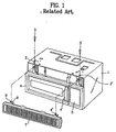
- the outer case 1 has fastening holes 2 and 2' for coupling a vent grill 7 to be described below.
- the fastening holes 2 and 2' are provided with fastening screws 3, and 3' for fastening the vent grill 7 thereto.
- the door 4 has a hand grip 4' for opening/closing the door.
- the control panel 5 is a part for conducting various operation of the microwave oven.
- vent grill 7 in an upper part of the front surface of the microwave oven fitted in a lateral direction.
- the vent grill 7 provides ventilation between inside and outside of the microwave oven.
- the vent grill 7 is an inlet of air for cooling an electric fitting room, or air supplied into the cooking chamber, or an outlet of air discharged from inside to outside of the microwave oven.
- vent grill 7 There are fasting pieces 8 and 8' at both sides of a rear surface of the vent grill 7 each having a fastening hole 9 for screwing a screw 3 or 3'.
- the vent grill 7 is in general injection molded, and the fastening pieces 8 and 8' are not provided with a structure, such as boss, for fastening the fastening screws 3 and 3', due to an injection molding characteristic.
- the vent grill 7 is position at upper part of the front surface of the related art microwave oven when the vent grill is fitted to the outer case 1, such that the fasting holes 9 in the fastening pieces 8 and 8' are matched to the fastening holes 2 and 2' on the outer case 1 for fixing the vent grill 7 to the outer case 1 by screwing the screws 3 and 3' through the outer case 1 and the fastening pieces 8 and 8'.
- vent grill 7 Before the vent grill 7 is put on the upper part of the front surface of the microwave oven, clips (not shown) are inserted to the fastening pieces 8 and 8' on the vent grill 7.
- the pre-fitting of the clips to the fastening pieces 8 and 8' required for assembly of the vent grill 7 before the fastening screws 3 and 3' are screwed is a cumbersome work.
- the separate fabrication of the vent grill 7 with subsequent assembly to the upper part of the microwave oven requires a complicate management and assembly, and a high production cost.
- the separate fabrication of the vent grill 7 with subsequent assembly to the upper part of the microwave oven causes gaps with the door 4 or the control panel 5 due to an assembly tolerance, or deformation during use of the microwave oven, that result in a poor outer appearance.
- a microwave oven which comprises a main frame both of a cooking chamber and an electric fitting room is disclosed in EP 0 866 643 A2.
- the main frame has a plurality of vent holes in an upper part of a front surface thereof.
- the microwave oven further comprises a door in the front surface of the main frame for opening and closing, respectively the cooking chamber selectively.
- the microwave oven comprises a control panel in the front surface of the main frame in front of an electric fitting room.
- the present invention is directed to a microwave oven that substantially obviates one or more of the problems due to limitations and disadvantages of the related art.
- An object of the present invention is to provide a microwave oven which requires no separate assembly of the vent grill and simplifying a front structure of the microwave oven.
- the microwave oven includes a main frame both of a cooking chamber and an electric fitting room having a plurality of vent holes in an upper part of a front surface thereof, a door in the front surface of the main frame for opening/closing the cooking chamber selectively, a control panel in the front surface of the main frame in front of an electric fitting room, and a vent grill part formed as a unit with the door or the control panel so as to be spaced from vent holes in the front surface even if the door is closed, for communicating air inside and outside of the microwave oven.
- the vent grill part includes a louver at a position opposite to the vent holes in the upper part of the front surface of the main frame.
- the foregoing microwave oven of the present invention minimizes the number of components, and gaps between components fitted in a front surface of the microwave oven.
- FIGS. 3 and 4 illustrate a preferred embodiment of the present invention.
- a cooking chamber 32 for cooking food by a microwave and heat from a heater, and an electric fitting room in a main frame 30 of the microwave oven.
- An inlet of the cooking chamber 32 is opened in a front surface 34 of the main frame 30.
- the plurality of vent holes 36 and 36' arranged in a matrix in the front surface 34 are provided for the cooking chamber 32 and the electric fitting room.
- a door 40 in one side of the front surface 34 of the main frame 30 for opening/closing the cooking chamber 32, as a fore end of the door 40 is rotated round a hinge (no shown) fitted at one end to permit the cooking chamber 32 to communicate with outside of microwave oven selectively, and there is a hand grip 42 on the fore end of the door 40 at one side of the door 40.
- a door panel 44 around the door 40.
- vent grill part 46 formed as one unit with, and extended upward from a top end of, the door panel 44 for covering the vent holes 36 from user's vision.
- the vent grill part 46 is provided on the door panel 44.
- the vent grill part 46 has an upper part with reference to the vent holes 36 having a thickness smaller than a lower part thereof, to open the upper part. Accordingly, as shown in FIG. 4, when the door 40 is closed, air inside and outside of the microwave oven communicate through the vent holes 36 in the front surface 34 and an opened space in the upper part of the vent grill part 46.
- a control panel 50 in one side of the cooking chamber 32 provided with various function buttons (not shown) for operating the microwave oven having a display part for indicating operation states of the microwave oven.
- There is an electric fitting room in rear of the control panel 50 having electric fittings for generating the microwave.
- the vent grill part 56 also has an upper part with reference to the vent holes 36' having a thickness smaller than a lower part thereof, to open the upper part. According to this, the vent grill part 56 has an opened top end, allowing communication between an inside and an outside of the microwave oven through the vent holes 36' in the front surface 34.
- a reference symbol 60 denotes an outer case forming an outer appearance of the microwave oven.
- the vent grill parts 46 and 56 are formed on tops of the door 40 and the control panel 50 as one unit, respectively.
- the vent grill parts 46 and 56 cover the vent holes 36 and 36' in the front surface 34 from external view.
- the vent holes 36 and 36' can be seen at an angle from above the microwave oven, which state is illustrated in FIG. 4. Therefore, while the vent grill part 46 on top of the door 40 covers the vent holes 36 in the front surface 34 from frontal view, the vent grill part 46 permits air inside and outside of the microwave oven to communicate through the vent holes 36 as the vent grill part 46 is spaced from the vent holes 36.
- vent grill part 56 on top of the control panel 50 also covers the vent holes 36' in the front surface 34 from frontal view, the vent grill part 56 permits air inside and outside of the microwave oven to communicate through the vent holes 36' as the vent grill part 56 is spaced from the vent holes 36'. Therefore, as shown in FIG. 4, when food is cook in a state the door 40 is closed, ventilation of the air inside and outside of the microwave oven is made through the vent holes 36 and 36' and the opened top parts of the vent grill parts 46 and 56.
- the present invention suggests to provide only a door and a control panel, without a separate vent grill in a front surface of the microwave oven, for making a front surface structure of the microwave oven simple different from in the related art in which a vent grill is provided separately, and an assembly process simple different from the related art in which a process for assembling the vent grill is required separately, thereby improving assembly process.
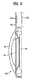
- FIG. 5 illustrates a section of key parts of a microwave oven in accordance with another preferred embodiment of the present invention.
- a louver 48 on top of a vent grill part 46 formed as one unit with a door 40, so that the vent holes 36 in a front surface 34 of the main frame 30 is in communication with a front part of the door 40.
- a top of the vent grill part 46 is also opened.
- the embodiment permits communication between inside and outside of the microwave oven through the vent holes 36, the louver 48 in the vent grill part 46, and the opened top part, on the same time, for more smooth air flow between inside/outside of the vent holes 36.
- a louver may be formed in the vent grill part 56 of the control panel 50, for air communication between inside/outside of the microwave oven through the ventilation hole 36'.
- the vent grill part may be formed at any one side of the door and the control panel.
- a position of the vent holes may be adjusted depending on a design condition, to form the vent grill part either of the door or the control panel.
- the microwave oven of the present invention has the following advantages.
- vent grill 46, 56 as one unit with the door 40 and the control panel 50 for communication of air between inside and outside of the microwave oven, dispensing with a separate vent grill, minimizes a number of components of the front surface 34 of the microwave oven, improves assembly work of the microwave oven, that drops a cost for the microwave open.
- the minimized number of front surface components of the microwave oven in turn minimizes gaps between the components, prevents formation of gaps caused by assembly tolerances or distortion during use of the microwave oven, thereby improving a frontal outer appearance of the microwave oven.
- the relatively simplified components improve assembly work, and drops a production cost.
Landscapes
- Physics & Mathematics (AREA)
- Electromagnetism (AREA)
- Engineering & Computer Science (AREA)
- Chemical & Material Sciences (AREA)
- Combustion & Propulsion (AREA)
- Mechanical Engineering (AREA)
- General Engineering & Computer Science (AREA)
- Electric Ovens (AREA)
- Constitution Of High-Frequency Heating (AREA)
Claims (4)
- Mikrowellenherd, aufweisend:einen Hauptrahmen (30) sowohl einer Kochkammer (32) als auch einer Elektronikkammer, mit einer Vielzahl von Entlüftungslöchern (36, 36') in einem oberen Teil einer Frontfläche (34) davon;eine Tür (40) in der Frontfläche (34) des Hauptrahmens (30) zum selektiven Öffnen/Schließen der Kochkammer (32);ein Bedienfeld (50) in der Frontfläche (34) des Hauptrahmens (30) vor einer Elektronikkammer, gekennzeichnet durch
einen Entlüftungsgitterabschnitt (46, 56), der als eine Einheit mit der Tür (40) oder dem Bedienfeld (50) so ausgebildet ist, dass er von den Entlüftungslöchern (36, 36') in der Frontfläche (34) beabstandet ist, selbst wenn die Tür (40) geschlossen ist, zum Austausch von Luft innerhalb und außerhalb des Mikrowellenherdes. - Mikrowellenherd nach Anspruch 1, dadurch gekennzeichnet, dass der Entlüftungsgitterabschnitt (46, 56) einen oberen Teil in Bezug auf die Entlüftungslöcher (36, 36') mit einer Dicke aufweist, die geringer als ein unterer Teil davon ist, um ein oberes Ende davon zu öffnen.
- Mikrowellenherd nach Anspruch 1 oder 2, dadurch gekennzeichnet, dass die Entlüftungslöcher (36, 36') in wenigstens einem eines oberen Teils der Kochkammer (32) oder eines oberen Teils des Elektroausrüstungsraums in der Frontfläche (34) des Hauptrahmens (30) ausgebildet sind.
- Mikrowellenherd nach einem der Ansprüche 1 bis 3, dadurch gekennzeichnet, dass der Entlüftungsgitterabschnitt (46, 56) einen Lüftungsschlitz (48) an einer Position aufweist, die den Entlüftungslöchern (36, 36') in dem oberen Teil der Frontfläche (34) des Hauptrahmens (30) gegenüberliegt.
Applications Claiming Priority (2)
| Application Number | Priority Date | Filing Date | Title |
|---|---|---|---|
| KR10-2000-0079361A KR100402579B1 (ko) | 2000-12-20 | 2000-12-20 | 전자레인지 |
| KR2000079361 | 2000-12-20 |
Publications (3)
| Publication Number | Publication Date |
|---|---|
| EP1217875A2 EP1217875A2 (de) | 2002-06-26 |
| EP1217875A3 EP1217875A3 (de) | 2004-07-14 |
| EP1217875B1 true EP1217875B1 (de) | 2006-04-26 |
Family
ID=36320183
Family Applications (1)
| Application Number | Title | Priority Date | Filing Date |
|---|---|---|---|
| EP01127146A Expired - Lifetime EP1217875B1 (de) | 2000-12-20 | 2001-11-15 | Mikrowellenofengehäuse |
Country Status (6)
| Country | Link |
|---|---|
| US (1) | US6420690B1 (de) |
| EP (1) | EP1217875B1 (de) |
| KR (1) | KR100402579B1 (de) |
| CN (1) | CN1137347C (de) |
| AT (1) | ATE324767T1 (de) |
| DE (1) | DE60119071T2 (de) |
Families Citing this family (18)
| Publication number | Priority date | Publication date | Assignee | Title |
|---|---|---|---|---|
| KR100485572B1 (ko) * | 2002-06-29 | 2005-04-28 | 삼성전자주식회사 | 벽걸이형 전자렌지 |
| US7569675B2 (en) * | 2002-09-11 | 2009-08-04 | Spring Bioscience Corporation | High affinity monoclonal antibody for recognizing the progesterone receptor (PR) and method for creating the antibody |
| KR100848161B1 (ko) * | 2002-11-29 | 2008-07-23 | 삼성전자주식회사 | 공기정화장치를 구비한 조리기 |
| KR100577196B1 (ko) | 2003-12-02 | 2006-05-10 | 엘지전자 주식회사 | 커피 메이커 겸용 전자레인지 및 그 제어방법 |
| JP2006010122A (ja) * | 2004-06-23 | 2006-01-12 | Matsushita Electric Ind Co Ltd | レンジフード付き高周波加熱装置 |
| USD546111S1 (en) * | 2004-11-06 | 2007-07-10 | Lg Electronics Inc. | Coffee maker-combined microwave oven |
| FR2885003B1 (fr) * | 2005-04-22 | 2007-06-29 | Premark Feg Llc | Four a micro-ondes avec conduit d'air de refroidissement |
| KR100862112B1 (ko) * | 2006-09-01 | 2008-10-09 | 엘지전자 주식회사 | 조리기기 |
| KR20080024022A (ko) * | 2006-09-12 | 2008-03-17 | 엘지전자 주식회사 | 조리기기 |
| US7825358B2 (en) | 2006-09-01 | 2010-11-02 | Lg Electronics Inc. | Cooking apparatus having rear component space |
| KR100872221B1 (ko) * | 2006-09-12 | 2008-12-05 | 엘지전자 주식회사 | 조리기기 |
| KR100879778B1 (ko) * | 2007-01-26 | 2009-01-23 | 엘지전자 주식회사 | 후드 겸용 전자레인지의 부품서비스구조 |
| KR101450879B1 (ko) * | 2007-11-28 | 2014-10-14 | 엘지전자 주식회사 | 밴트그릴 |
| US9191999B2 (en) * | 2009-09-01 | 2015-11-17 | Manitowoc Foodservice Companies, Llc | Method and apparatus for venting a cooking device |
| USD957190S1 (en) | 2019-06-13 | 2022-07-12 | Whirlpool Corporation | Appliance recessed window bezel |
| USD788523S1 (en) | 2014-02-25 | 2017-06-06 | Whirlpool Corporation | Appliance recessed window bezel |
| KR101674293B1 (ko) * | 2015-03-09 | 2016-11-08 | 엘지전자 주식회사 | 조리기기 |
| CN106152189B (zh) * | 2016-08-15 | 2024-03-22 | 珠海格力电器股份有限公司 | 微波炉及其进风结构 |
Family Cites Families (11)
| Publication number | Priority date | Publication date | Assignee | Title |
|---|---|---|---|---|
| IT7820682U1 (it) * | 1978-02-02 | 1979-08-02 | Ire Ind Riunite Eurodomestici S P A | Porta per forno di cottura |
| US4184945A (en) * | 1978-06-12 | 1980-01-22 | Litton Systems, Inc. | Microwave wall oven air flow system |
| JPS5927135A (ja) * | 1982-08-06 | 1984-02-13 | Matsushita Electric Ind Co Ltd | 加熱調理器 |
| JPH0191804U (de) * | 1987-12-09 | 1989-06-16 | ||
| JPH0834124B2 (ja) * | 1988-09-06 | 1996-03-29 | 松下電器産業株式会社 | 高周波加熱装置 |
| JPH03513U (de) * | 1989-05-25 | 1991-01-07 | ||
| JP2502373B2 (ja) * | 1989-05-30 | 1996-05-29 | 日産自動車株式会社 | 車両用油圧供給装置 |
| JPH0740216B2 (ja) * | 1989-09-19 | 1995-05-01 | 株式会社富士通ゼネラル | 表示部の角度調整装置 |
| US5387258A (en) * | 1991-12-30 | 1995-02-07 | Fulgor S.P.A. | Self-cleaning oven |
| JPH09229377A (ja) * | 1996-02-26 | 1997-09-05 | Sharp Corp | 電子レンジ |
| KR100229138B1 (ko) * | 1997-03-22 | 1999-11-01 | 윤종용 | 전자렌지의 필터장치 |
-
2000
- 2000-12-20 KR KR10-2000-0079361A patent/KR100402579B1/ko not_active Expired - Fee Related
-
2001
- 2001-08-10 US US09/925,610 patent/US6420690B1/en not_active Expired - Fee Related
- 2001-09-03 CN CNB011236752A patent/CN1137347C/zh not_active Expired - Fee Related
- 2001-11-15 AT AT01127146T patent/ATE324767T1/de not_active IP Right Cessation
- 2001-11-15 DE DE60119071T patent/DE60119071T2/de not_active Expired - Fee Related
- 2001-11-15 EP EP01127146A patent/EP1217875B1/de not_active Expired - Lifetime
Also Published As
| Publication number | Publication date |
|---|---|
| EP1217875A2 (de) | 2002-06-26 |
| US6420690B1 (en) | 2002-07-16 |
| DE60119071T2 (de) | 2006-11-02 |
| CN1360175A (zh) | 2002-07-24 |
| DE60119071D1 (de) | 2006-06-01 |
| US20020074330A1 (en) | 2002-06-20 |
| KR100402579B1 (ko) | 2003-10-22 |
| EP1217875A3 (de) | 2004-07-14 |
| CN1137347C (zh) | 2004-02-04 |
| KR20020050026A (ko) | 2002-06-26 |
| ATE324767T1 (de) | 2006-05-15 |
Similar Documents
| Publication | Publication Date | Title |
|---|---|---|
| US6420690B1 (en) | Microwave oven having a vent grill formed as part of a door and/or control panel | |
| US6242725B1 (en) | Heat cooking device allowing control of fan rotation number | |
| US20090321430A1 (en) | Cooking apparatus | |
| US10961755B2 (en) | Oven | |
| KR100233437B1 (ko) | 전자렌지의 도어 | |
| JPH07324754A (ja) | 電子レンジの冷却装置 | |
| JP3495614B2 (ja) | 加熱調理装置 | |
| CN213931069U (zh) | 一种烹饪设备的门体散热结构 | |
| US7554058B2 (en) | Domestic appliance, especially cooking appliance | |
| KR102850856B1 (ko) | 후드 겸용 전자 레인지 | |
| JPH1019269A (ja) | 電子レンジ | |
| CN214370418U (zh) | 一种微波炉风道结构 | |
| KR20000004451U (ko) | 전자렌지의 도어 | |
| KR20220056608A (ko) | 조리기기 | |
| US5895601A (en) | Door lock mechanism with a duct for a microwave oven | |
| KR20040059678A (ko) | 오븐레인지의 오븐 도어장치 | |
| KR100516614B1 (ko) | 전자레인지의 래치보드 | |
| KR20250142038A (ko) | 오븐 | |
| KR200337673Y1 (ko) | 전자레인지 스테인리스카바의 접지구조 | |
| KR200378446Y1 (ko) | 전자레인지의프론트브라켓장착구조 | |
| KR100518442B1 (ko) | 전자레인지의 에어안내구조 | |
| KR20060037001A (ko) | 전기오븐 도어의 핸들조립체 | |
| KR20010060657A (ko) | 후드겸용 전자레인지의 전면구조 | |
| KR20230086906A (ko) | 컨트롤 박스를 포함하는 오븐 | |
| KR19990009418A (ko) | 전자렌지의 도어 |
Legal Events
| Date | Code | Title | Description |
|---|---|---|---|
| PUAI | Public reference made under article 153(3) epc to a published international application that has entered the european phase |
Free format text: ORIGINAL CODE: 0009012 |
|
| AK | Designated contracting states |
Kind code of ref document: A2 Designated state(s): AT BE CH CY DE DK ES FI FR GB GR IE IT LI LU MC NL PT SE TR |
|
| AX | Request for extension of the european patent |
Free format text: AL;LT;LV;MK;RO;SI |
|
| PUAL | Search report despatched |
Free format text: ORIGINAL CODE: 0009013 |
|
| AK | Designated contracting states |
Kind code of ref document: A3 Designated state(s): AT BE CH CY DE DK ES FI FR GB GR IE IT LI LU MC NL PT SE TR |
|
| AX | Request for extension of the european patent |
Extension state: AL LT LV MK RO SI |
|
| 17P | Request for examination filed |
Effective date: 20040715 |
|
| 17Q | First examination report despatched |
Effective date: 20040923 |
|
| AKX | Designation fees paid |
Designated state(s): AT BE CH CY DE DK ES FI FR GB GR IE IT LI LU MC NL PT SE TR |
|
| GRAP | Despatch of communication of intention to grant a patent |
Free format text: ORIGINAL CODE: EPIDOSNIGR1 |
|
| GRAS | Grant fee paid |
Free format text: ORIGINAL CODE: EPIDOSNIGR3 |
|
| GRAA | (expected) grant |
Free format text: ORIGINAL CODE: 0009210 |
|
| AK | Designated contracting states |
Kind code of ref document: B1 Designated state(s): AT BE CH CY DE DK ES FI FR GB GR IE IT LI LU MC NL PT SE TR |
|
| PG25 | Lapsed in a contracting state [announced via postgrant information from national office to epo] |
Ref country code: BE Free format text: LAPSE BECAUSE OF FAILURE TO SUBMIT A TRANSLATION OF THE DESCRIPTION OR TO PAY THE FEE WITHIN THE PRESCRIBED TIME-LIMIT Effective date: 20060426 Ref country code: IT Free format text: LAPSE BECAUSE OF FAILURE TO SUBMIT A TRANSLATION OF THE DESCRIPTION OR TO PAY THE FEE WITHIN THE PRESCRIBED TIME-LIMIT;WARNING: LAPSES OF ITALIAN PATENTS WITH EFFECTIVE DATE BEFORE 2007 MAY HAVE OCCURRED AT ANY TIME BEFORE 2007. THE CORRECT EFFECTIVE DATE MAY BE DIFFERENT FROM THE ONE RECORDED. Effective date: 20060426 Ref country code: CH Free format text: LAPSE BECAUSE OF FAILURE TO SUBMIT A TRANSLATION OF THE DESCRIPTION OR TO PAY THE FEE WITHIN THE PRESCRIBED TIME-LIMIT Effective date: 20060426 Ref country code: LI Free format text: LAPSE BECAUSE OF FAILURE TO SUBMIT A TRANSLATION OF THE DESCRIPTION OR TO PAY THE FEE WITHIN THE PRESCRIBED TIME-LIMIT Effective date: 20060426 Ref country code: NL Free format text: LAPSE BECAUSE OF FAILURE TO SUBMIT A TRANSLATION OF THE DESCRIPTION OR TO PAY THE FEE WITHIN THE PRESCRIBED TIME-LIMIT Effective date: 20060426 Ref country code: FI Free format text: LAPSE BECAUSE OF FAILURE TO SUBMIT A TRANSLATION OF THE DESCRIPTION OR TO PAY THE FEE WITHIN THE PRESCRIBED TIME-LIMIT Effective date: 20060426 Ref country code: AT Free format text: LAPSE BECAUSE OF FAILURE TO SUBMIT A TRANSLATION OF THE DESCRIPTION OR TO PAY THE FEE WITHIN THE PRESCRIBED TIME-LIMIT Effective date: 20060426 |
|
| REG | Reference to a national code |
Ref country code: GB Ref legal event code: FG4D |
|
| REG | Reference to a national code |
Ref country code: IE Ref legal event code: FG4D |
|
| REF | Corresponds to: |
Ref document number: 60119071 Country of ref document: DE Date of ref document: 20060601 Kind code of ref document: P |
|
| PG25 | Lapsed in a contracting state [announced via postgrant information from national office to epo] |
Ref country code: DK Free format text: LAPSE BECAUSE OF FAILURE TO SUBMIT A TRANSLATION OF THE DESCRIPTION OR TO PAY THE FEE WITHIN THE PRESCRIBED TIME-LIMIT Effective date: 20060726 Ref country code: SE Free format text: LAPSE BECAUSE OF FAILURE TO SUBMIT A TRANSLATION OF THE DESCRIPTION OR TO PAY THE FEE WITHIN THE PRESCRIBED TIME-LIMIT Effective date: 20060726 |
|
| PG25 | Lapsed in a contracting state [announced via postgrant information from national office to epo] |
Ref country code: ES Free format text: LAPSE BECAUSE OF FAILURE TO SUBMIT A TRANSLATION OF THE DESCRIPTION OR TO PAY THE FEE WITHIN THE PRESCRIBED TIME-LIMIT Effective date: 20060806 |
|
| PG25 | Lapsed in a contracting state [announced via postgrant information from national office to epo] |
Ref country code: PT Free format text: LAPSE BECAUSE OF FAILURE TO SUBMIT A TRANSLATION OF THE DESCRIPTION OR TO PAY THE FEE WITHIN THE PRESCRIBED TIME-LIMIT Effective date: 20060926 |
|
| REG | Reference to a national code |
Ref country code: CH Ref legal event code: PL |
|
| NLV1 | Nl: lapsed or annulled due to failure to fulfill the requirements of art. 29p and 29m of the patents act | ||
| ET | Fr: translation filed | ||
| PG25 | Lapsed in a contracting state [announced via postgrant information from national office to epo] |
Ref country code: IE Free format text: LAPSE BECAUSE OF NON-PAYMENT OF DUE FEES Effective date: 20061115 |
|
| PG25 | Lapsed in a contracting state [announced via postgrant information from national office to epo] |
Ref country code: MC Free format text: LAPSE BECAUSE OF NON-PAYMENT OF DUE FEES Effective date: 20061130 |
|
| PLBE | No opposition filed within time limit |
Free format text: ORIGINAL CODE: 0009261 |
|
| STAA | Information on the status of an ep patent application or granted ep patent |
Free format text: STATUS: NO OPPOSITION FILED WITHIN TIME LIMIT |
|
| 26N | No opposition filed |
Effective date: 20070129 |
|
| PG25 | Lapsed in a contracting state [announced via postgrant information from national office to epo] |
Ref country code: GR Free format text: LAPSE BECAUSE OF FAILURE TO SUBMIT A TRANSLATION OF THE DESCRIPTION OR TO PAY THE FEE WITHIN THE PRESCRIBED TIME-LIMIT Effective date: 20060727 |
|
| PG25 | Lapsed in a contracting state [announced via postgrant information from national office to epo] |
Ref country code: LU Free format text: LAPSE BECAUSE OF NON-PAYMENT OF DUE FEES Effective date: 20061115 Ref country code: TR Free format text: LAPSE BECAUSE OF FAILURE TO SUBMIT A TRANSLATION OF THE DESCRIPTION OR TO PAY THE FEE WITHIN THE PRESCRIBED TIME-LIMIT Effective date: 20060426 |
|
| PG25 | Lapsed in a contracting state [announced via postgrant information from national office to epo] |
Ref country code: CY Free format text: LAPSE BECAUSE OF FAILURE TO SUBMIT A TRANSLATION OF THE DESCRIPTION OR TO PAY THE FEE WITHIN THE PRESCRIBED TIME-LIMIT Effective date: 20060426 |
|
| PGFP | Annual fee paid to national office [announced via postgrant information from national office to epo] |
Ref country code: DE Payment date: 20081114 Year of fee payment: 8 |
|
| PGFP | Annual fee paid to national office [announced via postgrant information from national office to epo] |
Ref country code: FR Payment date: 20081112 Year of fee payment: 8 |
|
| PGFP | Annual fee paid to national office [announced via postgrant information from national office to epo] |
Ref country code: GB Payment date: 20081112 Year of fee payment: 8 |
|
| GBPC | Gb: european patent ceased through non-payment of renewal fee |
Effective date: 20091115 |
|
| REG | Reference to a national code |
Ref country code: FR Ref legal event code: ST Effective date: 20100730 |
|
| PG25 | Lapsed in a contracting state [announced via postgrant information from national office to epo] |
Ref country code: FR Free format text: LAPSE BECAUSE OF NON-PAYMENT OF DUE FEES Effective date: 20091130 |
|
| PG25 | Lapsed in a contracting state [announced via postgrant information from national office to epo] |
Ref country code: DE Free format text: LAPSE BECAUSE OF NON-PAYMENT OF DUE FEES Effective date: 20100601 |
|
| PG25 | Lapsed in a contracting state [announced via postgrant information from national office to epo] |
Ref country code: GB Free format text: LAPSE BECAUSE OF NON-PAYMENT OF DUE FEES Effective date: 20091115 |