EP1217879A2 - Verfahren und Einrichtung zur thermischen Konditionierung von elektronische augruppen enthaltenden Schränken - Google Patents
Verfahren und Einrichtung zur thermischen Konditionierung von elektronische augruppen enthaltenden Schränken Download PDFInfo
- Publication number
- EP1217879A2 EP1217879A2 EP01129577A EP01129577A EP1217879A2 EP 1217879 A2 EP1217879 A2 EP 1217879A2 EP 01129577 A EP01129577 A EP 01129577A EP 01129577 A EP01129577 A EP 01129577A EP 1217879 A2 EP1217879 A2 EP 1217879A2
- Authority
- EP
- European Patent Office
- Prior art keywords
- air
- temperature
- cabinet
- assemblies
- outside
- Prior art date
- Legal status (The legal status is an assumption and is not a legal conclusion. Google has not performed a legal analysis and makes no representation as to the accuracy of the status listed.)
- Granted
Links
- 230000000712 assembly Effects 0.000 title claims abstract description 31
- 238000000429 assembly Methods 0.000 title claims abstract description 31
- 238000000034 method Methods 0.000 title claims abstract description 14
- 230000003750 conditioning effect Effects 0.000 title claims abstract description 7
- 238000001816 cooling Methods 0.000 claims abstract description 60
- 238000009423 ventilation Methods 0.000 claims abstract description 13
- 238000004378 air conditioning Methods 0.000 claims description 9
- 238000001514 detection method Methods 0.000 claims 2
- 238000010586 diagram Methods 0.000 description 3
- 238000001704 evaporation Methods 0.000 description 3
- 230000008020 evaporation Effects 0.000 description 3
- 239000011796 hollow space material Substances 0.000 description 3
- 238000012423 maintenance Methods 0.000 description 2
- 239000000203 mixture Substances 0.000 description 2
- 238000005192 partition Methods 0.000 description 2
- 238000010276 construction Methods 0.000 description 1
- 238000013461 design Methods 0.000 description 1
- 239000006185 dispersion Substances 0.000 description 1
- 230000017525 heat dissipation Effects 0.000 description 1
- 239000012535 impurity Substances 0.000 description 1
- 238000005259 measurement Methods 0.000 description 1
- 238000010295 mobile communication Methods 0.000 description 1
- 238000012986 modification Methods 0.000 description 1
- 230000004048 modification Effects 0.000 description 1
- 238000012544 monitoring process Methods 0.000 description 1
- 230000010355 oscillation Effects 0.000 description 1
- 238000000926 separation method Methods 0.000 description 1
- 230000001052 transient effect Effects 0.000 description 1
- XLYOFNOQVPJJNP-UHFFFAOYSA-N water Substances O XLYOFNOQVPJJNP-UHFFFAOYSA-N 0.000 description 1
Images

Classifications
-
- H—ELECTRICITY
- H05—ELECTRIC TECHNIQUES NOT OTHERWISE PROVIDED FOR
- H05K—PRINTED CIRCUITS; CASINGS OR CONSTRUCTIONAL DETAILS OF ELECTRIC APPARATUS; MANUFACTURE OF ASSEMBLAGES OF ELECTRICAL COMPONENTS
- H05K7/00—Constructional details common to different types of electric apparatus
- H05K7/20—Modifications to facilitate cooling, ventilating, or heating
- H05K7/20536—Modifications to facilitate cooling, ventilating, or heating for racks or cabinets of standardised dimensions, e.g. electronic racks for aircraft or telecommunication equipment
- H05K7/207—Thermal management, e.g. cabinet temperature control
-
- F—MECHANICAL ENGINEERING; LIGHTING; HEATING; WEAPONS; BLASTING
- F24—HEATING; RANGES; VENTILATING
- F24F—AIR-CONDITIONING; AIR-HUMIDIFICATION; VENTILATION; USE OF AIR CURRENTS FOR SCREENING
- F24F1/00—Room units for air-conditioning, e.g. separate or self-contained units or units receiving primary air from a central station
- F24F1/02—Self-contained room units for air-conditioning, i.e. with all apparatus for treatment installed in a common casing
- F24F1/022—Self-contained room units for air-conditioning, i.e. with all apparatus for treatment installed in a common casing comprising a compressor cycle
- F24F1/027—Self-contained room units for air-conditioning, i.e. with all apparatus for treatment installed in a common casing comprising a compressor cycle mounted in wall openings, e.g. in windows
-
- H—ELECTRICITY
- H05—ELECTRIC TECHNIQUES NOT OTHERWISE PROVIDED FOR
- H05K—PRINTED CIRCUITS; CASINGS OR CONSTRUCTIONAL DETAILS OF ELECTRIC APPARATUS; MANUFACTURE OF ASSEMBLAGES OF ELECTRICAL COMPONENTS
- H05K7/00—Constructional details common to different types of electric apparatus
- H05K7/20—Modifications to facilitate cooling, ventilating, or heating
- H05K7/20536—Modifications to facilitate cooling, ventilating, or heating for racks or cabinets of standardised dimensions, e.g. electronic racks for aircraft or telecommunication equipment
- H05K7/20618—Air circulating in different modes under control of air guidance flaps
-
- F—MECHANICAL ENGINEERING; LIGHTING; HEATING; WEAPONS; BLASTING
- F24—HEATING; RANGES; VENTILATING
- F24F—AIR-CONDITIONING; AIR-HUMIDIFICATION; VENTILATION; USE OF AIR CURRENTS FOR SCREENING
- F24F11/00—Control or safety arrangements
- F24F11/0001—Control or safety arrangements for ventilation
- F24F2011/0006—Control or safety arrangements for ventilation using low temperature external supply air to assist cooling
-
- Y—GENERAL TAGGING OF NEW TECHNOLOGICAL DEVELOPMENTS; GENERAL TAGGING OF CROSS-SECTIONAL TECHNOLOGIES SPANNING OVER SEVERAL SECTIONS OF THE IPC; TECHNICAL SUBJECTS COVERED BY FORMER USPC CROSS-REFERENCE ART COLLECTIONS [XRACs] AND DIGESTS
- Y02—TECHNOLOGIES OR APPLICATIONS FOR MITIGATION OR ADAPTATION AGAINST CLIMATE CHANGE
- Y02B—CLIMATE CHANGE MITIGATION TECHNOLOGIES RELATED TO BUILDINGS, e.g. HOUSING, HOUSE APPLIANCES OR RELATED END-USER APPLICATIONS
- Y02B30/00—Energy efficient heating, ventilation or air conditioning [HVAC]
- Y02B30/54—Free-cooling systems
Definitions
- the present invention relates to the cabinets for electronic assemblies, in particular for telecommunication, and more in particular, object of the same is a method and equipment for the thermal conditioning of said cabinets.
- a first solution employs active (or closed circuit) air conditioning systems, whichever the outside temperature is: in the latter, air coming from the cabinets is cooled, and so cooled, it is reintroduced in the cabinets.
- active (or closed circuit) air conditioning systems are disclosed in JP-A-11083354 and JP-A-11135972. Being these systems always in operation, they show high power consumption. Moreover, they originate temperature short-term fluctuations, tied to the transient of the thermal cycle, which reduce the average time between failures. This is an important aspect for assemblies, such as base stations of mobile communication systems placed in areas comparatively difficult to reach by maintenance operators or anyway far from maintenance centres.
- the second solution employs a free ventilation cooling (known as "free cooling"), according to which air drawn from the external environment is let into the cabinet, and hot air coming from the cabinet is exhausted to the outside.
- free ventilation cooling An example is disclosed in WO-A-9414308.
- Free ventilation cooling systems are intrinsically free from short-term fluctuations, however, they are scarcely effective or unusable where there is not a sufficient differential between the outside temperature and the internal one.
- Scope of the invention is to give an air-conditioning method and equipment effective in any climatic condition, enabling a reduced power consumption and minimizing the temperature short-term fluctuations.
- the method according to the invention includes the following steps:
- the equipment according to the invention includes:
- the equipment is housed in a construction module built-in the cabinet to cool.
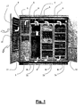
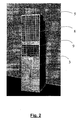
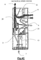
- a cabinet 1 including a given number of modules (three in the example shown in the in figure 2a, 2b, 2c) for electronic assemblies and their power supply devices, and an additional module 3 housing the air conditioning system of the invention.
- Modules 2a - 2c are open at top, to enable the exit of hot air to send to module 3, and at bottom for the inlet of cold air coming from module 3, as indicated by arrows A, B.
- the modules 2a - 2c have height such to define, with the ceiling of cabinet 1, a hollow space 4 to convey hot air to module 3, which in turn shows a rear lowered upper part, as it could be seen in detail in Figures 2 and 3 where this lowered portion has been denoted with the numeric reference 5.
- an inlet opening 6 is made for hot air conveyed by channel 4.
- a lower opening 7 enables to send cold air toward modules 2a-2c, through a hollow space similar to hollow space 4, not shown in the drawings.
- the module 3 houses a system capable of operating both in closed circuit and free ventilation mode. According to the invention, the two types of cooling can be separately and jointly actuated, according to the temperature conditions existing inside and outside the cabinet 1. In particular, three outside temperature bands are identified:
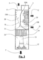
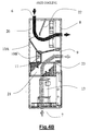
- the front wall of module 3 shows two superimposed openings 8, 9 closed with relevant grates, used for the exhaust of hot air to the environment (arrow C) and for the inlet of air sucked from the external environment (arrow D), respectively, during the free ventilation cooling.
- the upper part placed behind the grates 8, 9 forms an air handling section or chamber 20, and houses a gate 10, with a vertical section, L or obtuse angle shaped, which defines air paths requested by the cooling methods adopted on that moment.
- the position of gate 10 is represented in grey in the figure for the case of sole closed circuit cooling operating, while the position is white coloured when the sole free ventilation cooling is operating.
- the gate 10 is operated by a servomotor 11 controlled by a logic control unit 12 installed in the lower part of the module 3.
- the unit 12 is associated to appropriate sensors, not represented, both of the temperature outside and inside the cabinet, and of the relative humidity of external air, in order to decide the more appropriate cooling method in respect with particular climatic conditions.
- the logic unit can make the gate 10 assume any intermediate position among those shown in fig. 3.
- Devices like unit 12 are well known in the sector of air-conditioning plants.
- module 3 forms an evaporation section or chamber 21 and houses the compressor 13 of the mechanical cooling system and a dripping pan 14 for condensate water.
- the cabinet 1 shows also (see figure 1) closure doors, 16, and the door 15 shall in turn be equipped with slots 17, 18 for air passage, matching openings 8, 9. These openings are fit with relevant filters: the opening 18 is equipped with filter to hold air impurities, while opening 17 is fit with attenuation system for the noise cause by air exhaust.
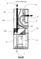
- Figures 4A - 4C show more in detail the air flows corresponding to the use of the sole closed circuit cooling, of the sole free ventilation cooling and of the mixed cooling.
- black arrows indicate hot air and white arrows cold air.
- the upper arm 10A of gate 10 rests against a partition 22 projecting downward from the module ceiling, while the other arm 10B rests against a partition 23 foreseen matching the separation area between chambers 20, 21.
- the gate 10 defines a passage carrying hot air entering the upper opening 6 towards the evaporation chamber 21 (where it is cooled, since the compressor 13 is operating) and from there, to the lower opening 7, while it prevents the passage of air itself towards opening 9 and the exhaust to the environment through this one.Possible external air entering opening 9 is diverted through opening 8 and re-inlet in the environment, without participating in the cooling process.
- the gate is at an intermediate position between those of figures 4A and 4B, enabling the passage to the evaporation section 21 both of air coming from the cabinet through opening 6, and of external air entering opening 9.
- the compressor 13 is operating and therefore also external air is cooled.
- the relevant proportions of the two air inlets will depend on the particular position of the gate, determined by the logic unit 14. This position shall be selected according to the temperature difference between internal and external air, and it could be modified by discrete steps or even continuously, as this difference varies.
- the operation condition corresponding to the intermediate band, for the major part of the operating time of the air-conditioned system during the year.
- the upper threshold could be included for instance between 30°C and 50°C
- the lower temperature threshold between 10°C and 25°C.
- the gate position there could be a variation in the gate position and if the difference between the internal and external temperature varies more than a threshold selected for instance between 2°C and 3°C.
- the humidity threshold causing to pass to the closed circuit cooling could be included for instance between 40% and 80%.
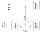
- FIG. 5 shows as a flow chart, the procedure of the invention.
- Te indicates the external air temperature
- T1 and T2 indicate the temperature upper and lower threshold, respectively
- U the relative humidity threshold. The cycle shown is repeated at pre-determined intervals. Considering the previous description the diagram is clear and does not require any additional explanation.
- Figure 6 shows on the contrary the checks on the external and internal temperature made during the mixed cooling operation.
- the difference ⁇ T between the two temperatures, between two subsequent monitoring instants t-1 and t varies of a quantity higher than a given threshold T3, the angle of gate 10 is changed, in order to vary the proportions of external and internal air.
- the essential advantage of the invention is that the free ventilation operation is expanded also to temperatures that otherwise could not employ it, and there is a reduction of the number of thermal cycles in the time unit.
Landscapes
- Engineering & Computer Science (AREA)
- Aviation & Aerospace Engineering (AREA)
- Physics & Mathematics (AREA)
- Thermal Sciences (AREA)
- Microelectronics & Electronic Packaging (AREA)
- Combustion & Propulsion (AREA)
- Chemical & Material Sciences (AREA)
- Mechanical Engineering (AREA)
- General Engineering & Computer Science (AREA)
- Cooling Or The Like Of Electrical Apparatus (AREA)
- Apparatus For Making Beverages (AREA)
- Non-Silver Salt Photosensitive Materials And Non-Silver Salt Photography (AREA)
- Solid-Sorbent Or Filter-Aiding Compositions (AREA)
Applications Claiming Priority (2)
| Application Number | Priority Date | Filing Date | Title |
|---|---|---|---|
| ITMI002799 | 2000-12-22 | ||
| IT2000MI002799A IT1319610B1 (it) | 2000-12-22 | 2000-12-22 | Procedimento e apparecchiatura per il condizionamento termico diarmadi contenenti apparecchiature elettroniche |
Publications (3)
| Publication Number | Publication Date |
|---|---|
| EP1217879A2 true EP1217879A2 (de) | 2002-06-26 |
| EP1217879A3 EP1217879A3 (de) | 2005-04-27 |
| EP1217879B1 EP1217879B1 (de) | 2009-10-28 |
Family
ID=11446301
Family Applications (1)
| Application Number | Title | Priority Date | Filing Date |
|---|---|---|---|
| EP01129577A Expired - Lifetime EP1217879B1 (de) | 2000-12-22 | 2001-12-12 | Verfahren und Einrichtung zur thermischen Konditionierung von elektronische augruppen enthaltenden Schränken |
Country Status (4)
| Country | Link |
|---|---|
| EP (1) | EP1217879B1 (de) |
| AT (1) | ATE447316T1 (de) |
| DE (1) | DE60140293D1 (de) |
| IT (1) | IT1319610B1 (de) |
Cited By (14)
| Publication number | Priority date | Publication date | Assignee | Title |
|---|---|---|---|---|
| EP1816408A1 (de) * | 2006-02-07 | 2007-08-08 | Emerson Network Power S.R.L. | Klimatisierungsvorrichtung mit freier Kühlung |
| EP1489894A4 (de) * | 2002-03-28 | 2009-02-18 | Mitsubishi Electric Corp | Kühlvorrichtung |
| WO2009055142A1 (en) * | 2007-10-25 | 2009-04-30 | Raytheon Company | System and method for cooling structures having both an active state and an inactive state |
| CN101963378A (zh) * | 2009-11-04 | 2011-02-02 | 阿尔西制冷工程技术(北京)有限公司 | 一种数据中心热点空调制冷系统 |
| ES2371194A1 (es) * | 2010-06-09 | 2011-12-28 | Gesab, S.A. | Método de acondicionamiento de aire para salas de equipos informáticos e instalación para llevar a cabo dicho método. |
| CN102401424A (zh) * | 2010-09-08 | 2012-04-04 | 苏州昆拓冷机有限公司 | 机柜空调器 |
| CN103153032A (zh) * | 2013-03-22 | 2013-06-12 | 杭州汉超科技有限公司 | 集成温控平衡机柜 |
| CN114126321A (zh) * | 2020-08-25 | 2022-03-01 | 中国移动通信集团设计院有限公司 | 机柜及控制方法 |
| CN114340362A (zh) * | 2022-02-14 | 2022-04-12 | 浙江德塔森特数据技术有限公司 | 一体化机柜及其控制方法、控制装置及可读存储介质 |
| CN114828578A (zh) * | 2022-04-29 | 2022-07-29 | 深圳市瀚强科技股份有限公司 | 液冷机柜设备 |
| US20220248571A1 (en) * | 2019-10-22 | 2022-08-04 | Huawei Technologies Co., Ltd. | Liquid Cooling Heat Dissipation System, Heat Dissipation Control Method, and Control Chip |
| IT202200016014A1 (it) * | 2022-07-28 | 2024-01-28 | Mitsubishi Electric Hydronics & It Cooling Systems S P A | Unita' di condizionamento d'aria migliorata |
| WO2024023751A1 (en) * | 2022-07-28 | 2024-02-01 | Mitsubishi Electric Hydronics & IT Cooling Systems S.p.A. | Improved air conditioning unit |
| US12560344B2 (en) | 2022-07-28 | 2026-02-24 | Mitsubishi Electric Hydronics & IT Cooling Systems S.p.A. | Air conditioning unit |
Families Citing this family (1)
| Publication number | Priority date | Publication date | Assignee | Title |
|---|---|---|---|---|
| CN111306747B (zh) * | 2020-03-27 | 2024-02-09 | 宁波奥克斯电气股份有限公司 | 电控箱降温控制方法、装置和空调器 |
Citations (3)
| Publication number | Priority date | Publication date | Assignee | Title |
|---|---|---|---|---|
| WO1994014308A1 (en) | 1992-12-15 | 1994-06-23 | Telefonaktiebolaget Lm Ericsson | Modular packaging system |
| JPH1183354A (ja) | 1997-09-04 | 1999-03-26 | Denso Corp | 冷却装置 |
| JPH11135972A (ja) | 1997-10-30 | 1999-05-21 | Denso Corp | 筐体冷却装置 |
Family Cites Families (5)
| Publication number | Priority date | Publication date | Assignee | Title |
|---|---|---|---|---|
| DE1233560B (de) * | 1961-05-15 | 1967-02-02 | Siemens Ag | Lueftereinrichtung fuer Geraete und Anlagen der elektrischen Nachrichtentechnik |
| US4495545A (en) * | 1983-03-21 | 1985-01-22 | Northern Telecom Limited | Enclosure for electrical and electronic equipment with temperature equalization and control |
| IT1208204B (it) * | 1986-02-19 | 1989-06-12 | Gte Telecom Spa | Dispositivo di trattamento dell'aria di raffreddamento per valvole trasmittenti. |
| GB8704411D0 (en) * | 1987-02-25 | 1987-04-01 | Gen Electric Co Plc | Cabinet |
| US6142866A (en) * | 1999-03-18 | 2000-11-07 | Nokia Telecommunications, Oy | Method and apparatus for providing air circulation control for a base transceiver station |
-
2000
- 2000-12-22 IT IT2000MI002799A patent/IT1319610B1/it active
-
2001
- 2001-12-12 AT AT01129577T patent/ATE447316T1/de not_active IP Right Cessation
- 2001-12-12 EP EP01129577A patent/EP1217879B1/de not_active Expired - Lifetime
- 2001-12-12 DE DE60140293T patent/DE60140293D1/de not_active Expired - Fee Related
Patent Citations (3)
| Publication number | Priority date | Publication date | Assignee | Title |
|---|---|---|---|---|
| WO1994014308A1 (en) | 1992-12-15 | 1994-06-23 | Telefonaktiebolaget Lm Ericsson | Modular packaging system |
| JPH1183354A (ja) | 1997-09-04 | 1999-03-26 | Denso Corp | 冷却装置 |
| JPH11135972A (ja) | 1997-10-30 | 1999-05-21 | Denso Corp | 筐体冷却装置 |
Cited By (16)
| Publication number | Priority date | Publication date | Assignee | Title |
|---|---|---|---|---|
| EP1489894A4 (de) * | 2002-03-28 | 2009-02-18 | Mitsubishi Electric Corp | Kühlvorrichtung |
| EP1816408A1 (de) * | 2006-02-07 | 2007-08-08 | Emerson Network Power S.R.L. | Klimatisierungsvorrichtung mit freier Kühlung |
| US9644869B2 (en) | 2007-10-25 | 2017-05-09 | Raytheon Company | System and method for cooling structures having both an active state and an inactive state |
| WO2009055142A1 (en) * | 2007-10-25 | 2009-04-30 | Raytheon Company | System and method for cooling structures having both an active state and an inactive state |
| CN101963378A (zh) * | 2009-11-04 | 2011-02-02 | 阿尔西制冷工程技术(北京)有限公司 | 一种数据中心热点空调制冷系统 |
| ES2371194A1 (es) * | 2010-06-09 | 2011-12-28 | Gesab, S.A. | Método de acondicionamiento de aire para salas de equipos informáticos e instalación para llevar a cabo dicho método. |
| CN102401424B (zh) * | 2010-09-08 | 2013-10-16 | 苏州昆拓冷机有限公司 | 机柜空调器 |
| CN102401424A (zh) * | 2010-09-08 | 2012-04-04 | 苏州昆拓冷机有限公司 | 机柜空调器 |
| CN103153032A (zh) * | 2013-03-22 | 2013-06-12 | 杭州汉超科技有限公司 | 集成温控平衡机柜 |
| US20220248571A1 (en) * | 2019-10-22 | 2022-08-04 | Huawei Technologies Co., Ltd. | Liquid Cooling Heat Dissipation System, Heat Dissipation Control Method, and Control Chip |
| CN114126321A (zh) * | 2020-08-25 | 2022-03-01 | 中国移动通信集团设计院有限公司 | 机柜及控制方法 |
| CN114340362A (zh) * | 2022-02-14 | 2022-04-12 | 浙江德塔森特数据技术有限公司 | 一体化机柜及其控制方法、控制装置及可读存储介质 |
| CN114828578A (zh) * | 2022-04-29 | 2022-07-29 | 深圳市瀚强科技股份有限公司 | 液冷机柜设备 |
| IT202200016014A1 (it) * | 2022-07-28 | 2024-01-28 | Mitsubishi Electric Hydronics & It Cooling Systems S P A | Unita' di condizionamento d'aria migliorata |
| WO2024023751A1 (en) * | 2022-07-28 | 2024-02-01 | Mitsubishi Electric Hydronics & IT Cooling Systems S.p.A. | Improved air conditioning unit |
| US12560344B2 (en) | 2022-07-28 | 2026-02-24 | Mitsubishi Electric Hydronics & IT Cooling Systems S.p.A. | Air conditioning unit |
Also Published As
| Publication number | Publication date |
|---|---|
| EP1217879B1 (de) | 2009-10-28 |
| EP1217879A3 (de) | 2005-04-27 |
| ATE447316T1 (de) | 2009-11-15 |
| IT1319610B1 (it) | 2003-10-20 |
| ITMI20002799A1 (it) | 2002-06-22 |
| DE60140293D1 (de) | 2009-12-10 |
Similar Documents
| Publication | Publication Date | Title |
|---|---|---|
| EP1217879B1 (de) | Verfahren und Einrichtung zur thermischen Konditionierung von elektronische augruppen enthaltenden Schränken | |
| US8621884B2 (en) | AC unit with economizer and sliding damper assembly | |
| CN113840510B (zh) | 机柜 | |
| CN1085650A (zh) | 间接冷却式冰箱 | |
| CN201193854Y (zh) | 双模式工业用散热空调 | |
| US4245481A (en) | Supplemental cold-air supply system | |
| US6701737B2 (en) | Integral-type air conditioner | |
| US5345770A (en) | Low-temperature regenerative type refrigerator | |
| JP3956418B2 (ja) | 筐体冷却装置 | |
| JPH04177074A (ja) | 冷蔵庫 | |
| CN213548159U (zh) | 高换热效能机柜空调器 | |
| EP0734505B1 (de) | Energieeffizientes hauskühlsystem | |
| JP4452215B2 (ja) | 冷却システム | |
| EP0541172A2 (de) | Kühlschrank mit mehreren Fächern ohne Eisbildung | |
| CN213973508U (zh) | 一种快速除霜的房车空调 | |
| CN111412541A (zh) | 多功能一体式空调 | |
| JP2001289552A (ja) | 冷蔵庫 | |
| KR200246356Y1 (ko) | 밀폐된 공간 냉방 장치 | |
| JP2002277002A (ja) | 筐体冷却システム | |
| CN220771539U (zh) | 冷柜 | |
| CN113654217A (zh) | 空调器的控制方法 | |
| CN221076657U (zh) | 空调机组 | |
| KR200317154Y1 (ko) | 통신장비용 냉각장치 | |
| CN223499674U (zh) | 一种风管机及空气调节系统 | |
| CN220771540U (zh) | 冷柜 |
Legal Events
| Date | Code | Title | Description |
|---|---|---|---|
| PUAI | Public reference made under article 153(3) epc to a published international application that has entered the european phase |
Free format text: ORIGINAL CODE: 0009012 |
|
| AK | Designated contracting states |
Kind code of ref document: A2 Designated state(s): AT BE CH CY DE DK ES FI FR GB GR IE IT LI LU MC NL PT SE TR |
|
| AX | Request for extension of the european patent |
Free format text: AL;LT;LV;MK;RO;SI |
|
| PUAL | Search report despatched |
Free format text: ORIGINAL CODE: 0009013 |
|
| AK | Designated contracting states |
Kind code of ref document: A3 Designated state(s): AT BE CH CY DE DK ES FI FR GB GR IE IT LI LU MC NL PT SE TR |
|
| AX | Request for extension of the european patent |
Extension state: AL LT LV MK RO SI |
|
| 17P | Request for examination filed |
Effective date: 20051021 |
|
| AKX | Designation fees paid |
Designated state(s): AT BE CH CY DE DK ES FI FR GB GR IE IT LI LU MC NL PT SE TR |
|
| RAP1 | Party data changed (applicant data changed or rights of an application transferred) |
Owner name: SIEMENS S.P.A. |
|
| RAP1 | Party data changed (applicant data changed or rights of an application transferred) |
Owner name: NOKIA SIEMENS NETWORKS GMBH & CO. KG |
|
| GRAP | Despatch of communication of intention to grant a patent |
Free format text: ORIGINAL CODE: EPIDOSNIGR1 |
|
| GRAS | Grant fee paid |
Free format text: ORIGINAL CODE: EPIDOSNIGR3 |
|
| GRAA | (expected) grant |
Free format text: ORIGINAL CODE: 0009210 |
|
| AK | Designated contracting states |
Kind code of ref document: B1 Designated state(s): AT BE CH CY DE DK ES FI FR GB GR IE IT LI LU MC NL PT SE TR |
|
| REG | Reference to a national code |
Ref country code: GB Ref legal event code: FG4D |
|
| REG | Reference to a national code |
Ref country code: CH Ref legal event code: EP |
|
| REG | Reference to a national code |
Ref country code: IE Ref legal event code: FG4D |
|
| REF | Corresponds to: |
Ref document number: 60140293 Country of ref document: DE Date of ref document: 20091210 Kind code of ref document: P |
|
| NLV1 | Nl: lapsed or annulled due to failure to fulfill the requirements of art. 29p and 29m of the patents act | ||
| PG25 | Lapsed in a contracting state [announced via postgrant information from national office to epo] |
Ref country code: PT Free format text: LAPSE BECAUSE OF FAILURE TO SUBMIT A TRANSLATION OF THE DESCRIPTION OR TO PAY THE FEE WITHIN THE PRESCRIBED TIME-LIMIT Effective date: 20100301 Ref country code: FI Free format text: LAPSE BECAUSE OF FAILURE TO SUBMIT A TRANSLATION OF THE DESCRIPTION OR TO PAY THE FEE WITHIN THE PRESCRIBED TIME-LIMIT Effective date: 20091028 Ref country code: SE Free format text: LAPSE BECAUSE OF FAILURE TO SUBMIT A TRANSLATION OF THE DESCRIPTION OR TO PAY THE FEE WITHIN THE PRESCRIBED TIME-LIMIT Effective date: 20091028 Ref country code: ES Free format text: LAPSE BECAUSE OF FAILURE TO SUBMIT A TRANSLATION OF THE DESCRIPTION OR TO PAY THE FEE WITHIN THE PRESCRIBED TIME-LIMIT Effective date: 20100208 |
|
| PG25 | Lapsed in a contracting state [announced via postgrant information from national office to epo] |
Ref country code: CY Free format text: LAPSE BECAUSE OF FAILURE TO SUBMIT A TRANSLATION OF THE DESCRIPTION OR TO PAY THE FEE WITHIN THE PRESCRIBED TIME-LIMIT Effective date: 20091028 |
|
| PG25 | Lapsed in a contracting state [announced via postgrant information from national office to epo] |
Ref country code: AT Free format text: LAPSE BECAUSE OF FAILURE TO SUBMIT A TRANSLATION OF THE DESCRIPTION OR TO PAY THE FEE WITHIN THE PRESCRIBED TIME-LIMIT Effective date: 20091028 Ref country code: BE Free format text: LAPSE BECAUSE OF FAILURE TO SUBMIT A TRANSLATION OF THE DESCRIPTION OR TO PAY THE FEE WITHIN THE PRESCRIBED TIME-LIMIT Effective date: 20091028 |
|
| PG25 | Lapsed in a contracting state [announced via postgrant information from national office to epo] |
Ref country code: DK Free format text: LAPSE BECAUSE OF FAILURE TO SUBMIT A TRANSLATION OF THE DESCRIPTION OR TO PAY THE FEE WITHIN THE PRESCRIBED TIME-LIMIT Effective date: 20091028 Ref country code: MC Free format text: LAPSE BECAUSE OF NON-PAYMENT OF DUE FEES Effective date: 20100701 |
|
| REG | Reference to a national code |
Ref country code: CH Ref legal event code: PL |
|
| PLBE | No opposition filed within time limit |
Free format text: ORIGINAL CODE: 0009261 |
|
| STAA | Information on the status of an ep patent application or granted ep patent |
Free format text: STATUS: NO OPPOSITION FILED WITHIN TIME LIMIT |
|
| REG | Reference to a national code |
Ref country code: FR Ref legal event code: ST Effective date: 20100831 |
|
| GBPC | Gb: european patent ceased through non-payment of renewal fee |
Effective date: 20100128 |
|
| 26N | No opposition filed |
Effective date: 20100729 |
|
| PG25 | Lapsed in a contracting state [announced via postgrant information from national office to epo] |
Ref country code: LI Free format text: LAPSE BECAUSE OF NON-PAYMENT OF DUE FEES Effective date: 20091231 Ref country code: CH Free format text: LAPSE BECAUSE OF NON-PAYMENT OF DUE FEES Effective date: 20091231 Ref country code: IE Free format text: LAPSE BECAUSE OF NON-PAYMENT OF DUE FEES Effective date: 20091212 Ref country code: GR Free format text: LAPSE BECAUSE OF FAILURE TO SUBMIT A TRANSLATION OF THE DESCRIPTION OR TO PAY THE FEE WITHIN THE PRESCRIBED TIME-LIMIT Effective date: 20100129 Ref country code: FR Free format text: LAPSE BECAUSE OF NON-PAYMENT OF DUE FEES Effective date: 20091231 |
|
| PG25 | Lapsed in a contracting state [announced via postgrant information from national office to epo] |
Ref country code: DE Free format text: LAPSE BECAUSE OF NON-PAYMENT OF DUE FEES Effective date: 20100701 |
|
| PG25 | Lapsed in a contracting state [announced via postgrant information from national office to epo] |
Ref country code: GB Free format text: LAPSE BECAUSE OF NON-PAYMENT OF DUE FEES Effective date: 20100128 |
|
| PG25 | Lapsed in a contracting state [announced via postgrant information from national office to epo] |
Ref country code: IT Free format text: LAPSE BECAUSE OF FAILURE TO SUBMIT A TRANSLATION OF THE DESCRIPTION OR TO PAY THE FEE WITHIN THE PRESCRIBED TIME-LIMIT Effective date: 20091028 |
|
| PG25 | Lapsed in a contracting state [announced via postgrant information from national office to epo] |
Ref country code: LU Free format text: LAPSE BECAUSE OF NON-PAYMENT OF DUE FEES Effective date: 20091212 |
|
| PG25 | Lapsed in a contracting state [announced via postgrant information from national office to epo] |
Ref country code: TR Free format text: LAPSE BECAUSE OF FAILURE TO SUBMIT A TRANSLATION OF THE DESCRIPTION OR TO PAY THE FEE WITHIN THE PRESCRIBED TIME-LIMIT Effective date: 20091028 |
|
| PG25 | Lapsed in a contracting state [announced via postgrant information from national office to epo] |
Ref country code: NL Free format text: LAPSE BECAUSE OF FAILURE TO SUBMIT A TRANSLATION OF THE DESCRIPTION OR TO PAY THE FEE WITHIN THE PRESCRIBED TIME-LIMIT Effective date: 20091028 |