EP1218681B1 - Verfahren und vorrichtung zum temperieren von elektronischen bauteilen - Google Patents
Verfahren und vorrichtung zum temperieren von elektronischen bauteilen Download PDFInfo
- Publication number
- EP1218681B1 EP1218681B1 EP00972694A EP00972694A EP1218681B1 EP 1218681 B1 EP1218681 B1 EP 1218681B1 EP 00972694 A EP00972694 A EP 00972694A EP 00972694 A EP00972694 A EP 00972694A EP 1218681 B1 EP1218681 B1 EP 1218681B1
- Authority
- EP
- European Patent Office
- Prior art keywords
- magazine
- temperature control
- holders
- carrier
- carriers
- Prior art date
- Legal status (The legal status is an assumption and is not a legal conclusion. Google has not performed a legal analysis and makes no representation as to the accuracy of the status listed.)
- Expired - Lifetime
Links
Images


Classifications
-
- H—ELECTRICITY
- H10—SEMICONDUCTOR DEVICES; ELECTRIC SOLID-STATE DEVICES NOT OTHERWISE PROVIDED FOR
- H10P—GENERIC PROCESSES OR APPARATUS FOR THE MANUFACTURE OR TREATMENT OF DEVICES COVERED BY CLASS H10
- H10P74/00—Testing or measuring during manufacture or treatment of wafers, substrates or devices
-
- B—PERFORMING OPERATIONS; TRANSPORTING
- B23—MACHINE TOOLS; METAL-WORKING NOT OTHERWISE PROVIDED FOR
- B23K—SOLDERING OR UNSOLDERING; WELDING; CLADDING OR PLATING BY SOLDERING OR WELDING; CUTTING BY APPLYING HEAT LOCALLY, e.g. FLAME CUTTING; WORKING BY LASER BEAM
- B23K1/00—Soldering, e.g. brazing, or unsoldering
- B23K1/008—Soldering within a furnace
-
- B—PERFORMING OPERATIONS; TRANSPORTING
- B23—MACHINE TOOLS; METAL-WORKING NOT OTHERWISE PROVIDED FOR
- B23K—SOLDERING OR UNSOLDERING; WELDING; CLADDING OR PLATING BY SOLDERING OR WELDING; CUTTING BY APPLYING HEAT LOCALLY, e.g. FLAME CUTTING; WORKING BY LASER BEAM
- B23K37/00—Auxiliary devices or processes, not specially adapted for a procedure covered by only one of the other main groups of this subclass
- B23K37/04—Auxiliary devices or processes, not specially adapted for a procedure covered by only one of the other main groups of this subclass for holding or positioning work
- B23K37/047—Auxiliary devices or processes, not specially adapted for a procedure covered by only one of the other main groups of this subclass for holding or positioning work moving work to adjust its position between soldering, welding or cutting steps
-
- F—MECHANICAL ENGINEERING; LIGHTING; HEATING; WEAPONS; BLASTING
- F26—DRYING
- F26B—DRYING SOLID MATERIALS OR OBJECTS BY REMOVING LIQUID THEREFROM
- F26B15/00—Machines or apparatus for drying objects with progressive movement; Machines or apparatus with progressive movement for drying batches of material in compact form
- F26B15/10—Machines or apparatus for drying objects with progressive movement; Machines or apparatus with progressive movement for drying batches of material in compact form with movement in a path composed of one or more straight lines, e.g. compound, the movement being in alternate horizontal and vertical directions
-
- F—MECHANICAL ENGINEERING; LIGHTING; HEATING; WEAPONS; BLASTING
- F27—FURNACES; KILNS; OVENS; RETORTS
- F27B—FURNACES, KILNS, OVENS OR RETORTS IN GENERAL; OPEN SINTERING OR LIKE APPARATUS
- F27B9/00—Furnaces through which the charge is moved mechanically, e.g. of tunnel type; Similar furnaces in which the charge moves by gravity
- F27B9/14—Furnaces through which the charge is moved mechanically, e.g. of tunnel type; Similar furnaces in which the charge moves by gravity characterised by the path of the charge during treatment; characterised by the means by which the charge is moved during treatment
- F27B9/142—Furnaces through which the charge is moved mechanically, e.g. of tunnel type; Similar furnaces in which the charge moves by gravity characterised by the path of the charge during treatment; characterised by the means by which the charge is moved during treatment the charge moving along a vertical axis
-
- B—PERFORMING OPERATIONS; TRANSPORTING
- B23—MACHINE TOOLS; METAL-WORKING NOT OTHERWISE PROVIDED FOR
- B23K—SOLDERING OR UNSOLDERING; WELDING; CLADDING OR PLATING BY SOLDERING OR WELDING; CUTTING BY APPLYING HEAT LOCALLY, e.g. FLAME CUTTING; WORKING BY LASER BEAM
- B23K2101/00—Articles made by soldering, welding or cutting
- B23K2101/36—Electric or electronic devices
- B23K2101/40—Semiconductor devices
Definitions
- the invention relates to a method for tempering those on supports electronic components, e.g. Semiconductor circuits, printed circuit boards and the like before or after soldering or for hardening the casting compound, in which the components on the carriers through an input slot in provided with temperature control elements and brought in by a the output slot opposite the input slot are conveyed out, the carrier being received in the housing by a sliding magazine be that with adjacent holders for receiving the individual Carrier is provided.
- electronic components e.g. Semiconductor circuits, printed circuit boards and the like before or after soldering or for hardening the casting compound
- a device for tempering workpieces is known from DE-OS 4020920 known.
- This device is a continuous furnace for Preheating workpieces to be processed.
- This Continuous furnace contains two transport systems, each in the manner of two side by side arranged paternoster are designed, which have an upper and a lower Conveyor belts contain guided conveyor belts.
- the direction of rotation of the pulleys is chosen so that the facing strands of the conveyor belts each run in the same direction so that on the conveyor belts attached receiving parts in the area between two conveyor belts either perform an upward or downward movement. Because of the arrangement two such transport systems in a row, i.e.
- the invention has for its object the sequence of the above To improve the tempering process. According to the invention, this is done by that the magazine gradually in one direction from a starting position and after Feed the first holder in this starting position into successive ones Recording positions is shifted, in which the individual holders are successively of the magazine can be loaded without gaps, whereupon after loading all Hold the fully filled magazine from the end position reached in the opposite direction Direction in rapid return to its starting position is postponed; in which the feeding of a carrier through the entrance slot and the resultant conveyance of that lying on the holder in question Carrier caused by the exit slot and a tempered carrier through a non-tempered carrier is replaced until all of the magazine holders are the same The carrier stays in the magazine again in its final position are, whereupon again after returning the magazine to the starting position the magazine is loaded step by step.
- each carrier prefferably be tempered for a specific one Period acted, namely their dwell time in the temperature control housing, defined through the period between two returns.
- the magazine is advantageously displaced in the temperature control housing in Vertical direction.
- This arrangement results in a relatively small footprint for the temperature control housing, since this only requires a vertical space, in which is a single up and down movement.
- This up and down movement you can move from the starting position to the end position either from below Design above or from top to bottom. If the magazine is moved There is a relief from the starting position to the end position from bottom to top for the quick return movement of the filled magazine from the end position back to the starting position, namely from top to bottom, since this is the Gravity supports this rapid movement.
- the device for carrying out the method described above acts it is a temperature control housing with a temperature control element Magazine, which is provided with holders for receiving the carrier and a sliding mechanism for moving the magazine contains.
- This device is designed according to the invention in such a way that the temperature control housing is approximately twice that Has the height of the magazine and in its central area the input slot and opposite the exit slot that the magazine with a shift mechanism for its gradual shift both for step-by-step gapless loading of the individual holders as well as through the loading caused gradual conveying out of each in alignment Position to the entrance and exit slot (receiving position) Holder is provided, and that the temperature control elements the interior of the housing bring to an adjustable temperature so that the Assume components at a desired temperature.
- the device according to the invention can be advantageously used for heating Use circuit boards in front of the melting zone of a soldering system, whereby the Tempering organs are formed by heaters. But it is also possible that To arrange the device following the melting zone of a soldering system, for which then the temperature control elements are to be formed by coolers.
- the device itself is a closed structure, it is possible to have several such devices adjacent to each other to arrange and their input and output slots to each other connect. This allows individual and gradual temperature control of components, especially the curing of casting compounds in the Connection with semiconductor circuits.
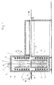
- the temperature control housing 1 is relatively thick temperature-insulating wall shown in which the magazine 2 is housed longitudinally displaceable.
- the magazine 2 is with individual holders 3 arranged one above the other at the same distance from one another, which are used for inclusion on individual supports 4.
- According to Figure 1 lies on the top holder 3 of the carrier 4.
- the magazine 2 is from the guide rails 5 and 6 out, which are attached to the wall of the temperature control housing 1.
- the here designed as a lifting mechanism 7 Sliding mechanism is provided, which has the take-up reel 8 on which the pull rope 9 can be wound up.
- the pull rope 9 is suspended on the bracket 10, the explained in more detail with regard to its design in connection with FIG. 5 becomes. By rolling up the pull rope 9, the magazine 2 is pushed up until it reaches its end position shown in FIG. 3, whereupon further below is received.
- the temperature control housing are for heating its interior as Radiant heater 11 trained heater and ventilation slots 12 are provided.
- the Ventilation slots 12 are in the wall of the temperature control 1 housed ducts 13 hot air supplied in addition to the radiant heaters 11 ensure heating of the interior of the temperature control housing 1. How can be seen are a larger over the inner wall of the temperature control housing 1 Number of radiant heaters 11 and ventilation slots 12 housed so that for the interior of the temperature control housing 1 a very uniform Soaking results.
- the two circulating air blowers 14 are additionally provided to the inside of the temperature control housing 1 air in its heated state in the entire interior distribute.
- the magazine 2 is intended for loading with the carriers 4, of which one, as already explained above, rests on the uppermost holder 3.
- the individual carriers are in the temperature control housing 1 through the input slot 15 conveyed, with the help of the conveyor belt 16, on the according Representation in Figure 1 already the carrier 17 with attached Semiconductor circuits 18 rests.
- the carrier 17 through the input slot 15 to the magazine 2 promoted, which is loaded with a carrier, as is the case with the carrier 4 the case is.
- the magazine 2 is now gradually raised by means of the lifting mechanism 7, in such a way that a holder 3 in an aligned position to the input slot 15, which the Recording position forms.
- the conveyor belt 16 can be used gradually bring the magazine 2 into the filled state, in which all Holder 3 of the magazine 2 are loaded with a carrier 4.
- FIG. 2 shows the arrangement according to FIG. 1 in a position in which the magazine 2 is partially loaded with carrier 4. This through the conveyor belt 16 loading of magazine 2 then continues step by step yourself. until magazine 2 is completely filled.
- FIG. 3 This state, in which the magazine 2 assumes its end position, is shown in FIG. 3 shown.
- magazine 2 was the lowest Holder 3 a carrier 4 has been supplied.
- the completely filled magazine 2 is then quickly returned to the position shown in FIG. 1 shown starting position shifted back, for which only a short period, e.g. a few seconds are required.
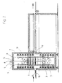
- FIG. 4 also shows how that from the temperature control housing 1 conveyed carrier 22 reach the area of a soldering system 23, where it is a well-known assembly in which the melting of the solder by a corresponding short temperature increase.
- the brackets 22 and 24 are by means of the conveyor belt 20 not only through the exit slot 19th taken over, but also transported through the soldering system 23 and finally reach another temperature control housing at the end of the soldering system 23 25, in which a necessary cooling of the carrier 24 is located on this Components.
- the same mechanism for is in the temperature control housing 25 the reciprocation of a magazine 26 housed in the same Way, as described in connection with the temperature control housing 1, is loaded with individual carriers, then the already tempered carriers 27 conveyed out of the temperature control housing 25 and from another Conveyor belt 28 are taken over for further processing. It plays the same process of lifting inside the temperature control housing 25 and pushing back the magazine 26 so that with respect to these operations the explanation of Figures 1 to 3 can be referenced.
- the temperature control housing 25 is included Cooler 29 provided that the carrier with the of them worn components to the temperature required for further processing be cooled.
- the temperature control housing 1 is filled with the magazine corresponding to the Representation shown in Figure 3, in contrast, rotated by 90 °. there are the temperature control elements shown in Figure 3 for the sake of Simplification and clarity of the illustration omitted.
- the magazine 2 hangs over the brackets 10 on the pull rope 9.
- the brackets 10 go into magazine 2 and thus form the connection between magazine 2 and the pull rope 9.
- the guide rail 5 is shown, the Guide rail 6 according to FIG. 3 is in the view according to FIG Guide rail 5 covered.
- the two guide rails 5 and 6 are sufficient for the guidance of the magazine 2 in its up and down movement.
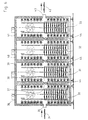
- FIG. 6 there are several temperature control housings with them in the sense of above explanations sliding magazines 30, 31, 32 and 33 shown, in which the respective input and output slots in Connect.
- This allows carriers through the input slot 35 of the first temperature control housing 36 fed into this and after tempering whose output slot 37, which is the input slot 38 of the Temperature control housing 39 forms, are promoted.
- the carrier by correspondingly designed further temperature control housings 40 and 41 after the respective temperature control in the previous temperature control housings convey until finally the carrier 42 through the output slot 43 of the last temperature control housing 41 are transported out.
- the handover of one temperature housing to another is expediently carried out by Transfer rollers 44 on which the from temperature housing to temperature housing supported carrier and because of the rotation of the transfer rollers 44th can be easily fed into the next temperature control housing.
- How 6 shows the individual temperature control housings in the area standardize their abutting wall. However, it is no requirement, it can of course be individual with complete Wall-mounted temperature control housing can be moved together.
- the individual temperature control housings 36 to 41 each have their own individual ones Treatment of the carriers carried through with the carriers carried by them Components too, for example starting with a relatively weak one Heating, which then increases over the following temperature housing 39 and 40 and finally decreases again via the temperature control housing 41. But it is Of course, any other gradual tempering is possible, depending on how the heating in the individual temperature control housings is selected. In particular is such a treatment in the hardening of casting compounds from Semiconductor circuits inexpensive, which for a thermal long-term process of have to go through up to several hours.
Landscapes
- Engineering & Computer Science (AREA)
- Mechanical Engineering (AREA)
- General Engineering & Computer Science (AREA)
- Physics & Mathematics (AREA)
- Optics & Photonics (AREA)
- Electric Connection Of Electric Components To Printed Circuits (AREA)
- Warehouses Or Storage Devices (AREA)
- Thermistors And Varistors (AREA)
- Crystals, And After-Treatments Of Crystals (AREA)
- Control Of Temperature (AREA)
Description
- Figur 1
- eine Seitenansicht eines Temperiergehäuses mit Magazin, das einer Aufschmelzzone einer Lötanlage vorgeordnet ist, und zwar in der Ausgangslage des Magazins,
- Figur 2
- die gleiche Anordnung mit angehobenem Magazin, das teilweise mit Trägem beschickt ist,
- Figur 3
- die gleiche Anordnung in der Endlage des Magazins, in dem dieses vollständig gefüllt ist und damit unmittelbar vor der schnellen Rückverschiebung in die Ausgangslage steht,
- Figur 4
- eine Lötanlage mit einem davor und dahinter angeordneten Temperiergehäuse,
- Figur 5
- das Temperiergehäuse in der Lage gemäß Figur 3, jedoch in einer um 90° gedrehten Seitenansicht,
- Figur 6
- eine Anordnung einer Mehrzahl von Temperiergehäusen unmittelbar nebeneinander mit in Verbindung stehenden Eingangs- und Ausgangsschlitzen.
- 1)
- Temperiergehäuse
- 2)
- Magazin
- 3)
- Halter
- 4)
- Träger
- 5)
- Führungsschienen
- 6)
- Führungsschienen
- 7)
- Hubmechanismus
- 8)
- Aufwickelrolle
- 9)
- Zugseil
- 10)
- Bügel
- 11)
- Heizstrahler
- 12)
- Lüftungsschlitze
- 13)
- Kanäle
- 14)
- Umluftgebläse
- 15)
- Eingangsschlitz
- 16)
- Transportband
- 17)
- Träger
- 18)
- Halbleiterschaltkreis
- 19)
- Ausgangsschlitz
- 20)
- Transportband
- 21)
- Träger
- 22)
- Träger
- 23)
- Lötanlage
- 24)
- Träger
- 25)
- Temperiergehäuse
- 26)
- Magazin
- 27)
- Träger
- 28)
- Transportband
- 29)
- Kühler
- 30)
- Magazin
- 31)
- Magazin
- 32)
- Magazin
- 33)
- Magazin
- 34)
- Träger
- 35)
- Eingangsschlitz
- 36)
- Temperiergehäuse
- 37)
- Ausgangsschlitz
- 38)
- Eingangsschlitz
- 39)
- Temperiergehäuse
- 40)
- Temperiergehäuse
- 41)
- Temperiergehäuse
- 42)
- Träger
- 43)
- Ausgangsschlitz
- 44)
- Übergaberollen
Claims (7)
- Verfahren zum Temperieren von auf Trägem befindlichen elektronischen Bauteilen, z.B. Halbleiterschaltkreisen (18), Leiterplatten und dergleichen vor oder nach dem Verlöten oder zum Aushärten von Vergussmasse, bei dem die Bauteile auf den Trägem (4, 17, 21, 22, 24, 27, 34, 42) durch einen Eingangsschlitz in ein mit Temperierorganen (11, 12) versehenes Temperiergehäuse (1) eingefördert und durch einen dem Eingangsschlitz (15) gegenüberliegenden Ausgangschlitz (19) ausgefördert werden, wobei die Träger (4, 17, 21, 22, 24, 27, 34, 42) in dem Gehäuse (1) von einem verschiebbaren Magazin (2) aufgenommen werden, das mit benachbart angeordneten Haltern (3) zur Aufnahme der einzelnen Träger (4, 17, 21, 22, 24, 27, 34, 42) versehen ist, dadurch gekennzeichnet, dass das Magazin (2) schrittweise in einer Richtung aus einer Ausgangslage und nach Beschicken des ersten Halters (3) in dieser Ausgangslage in aufeinanderfolgende Aufnahmepositionen verschoben wird, in denen nacheinander die einzelnen Halter des Magazins (2) lückenlos beschickt werden, woraufhin nach Beschickung sämtlicher Halter (3) das so voll gefüllte Magazin aus der dabei erreichten Endlage in entgegengesetzter Richtung in schnellem Rücklauf in seine Ausgangslage zurück verschoben wird, in der das Einfördern eines Trägers (4, 17, 21, 22, 24, 27, 34, 42) durch den Eingangsschlitz (15) und das hierdurch bewirkte Ausfördern des auf dem betreffenden Halter liegenden Trägers (22) durch den Ausgangsschlitz (19) bewirkt und ein temperierter Träger (22) durch einen nicht temperierten Träger (21) ersetzt wird, bis alle Halter (3) des Magazins (2) bei gleicher Verweilzeit der Träger im Magazin (2) in seiner erreichten Endlage wieder beschickt sind, woraufhin nach Rücklauf des Magazins (2) in die Ausgangslage erneut die schrittweise Beschickung des Magazins (2) erfolgt.
- Verfahren nach Anspruch 1, dadurch gekennzeichnet, dass die Verschiebung des Magazins (2) von der Ausgangslage in die Endlage in Vertikalrichtung von unten nach oben erfolgt.
- Verfahren nach Anspruch 1, dadurch gekennzeichnet, dass die Verschiebung des Magazins (2) von der Ausgangslage in die Endlage in Vertikalrichtung von oben nach unten erfolgt.
- Vorrichtung zur Durchführung des Verfahrens nach einem der Ansprüche 1 bis 3 an auf Trägern befindlichen elektronischen Bauteilen, wobei die Vorrichtung ein mit Temperierorganen (11, 12) versehenes Temperiergehäuse (1) mit einem Magazin (2) aufweist, das mit Haltern (3) zur Aufnahme der Träger (4, 17, 21, 22, 24, 27, 34, 42) versehen ist und einen Verschiebemechanismus (7, 8, 9) zur Verschiebung des Magazins (2) enthält, dadurch gekennzeichnet, dass das Temperiergehäuse (1) etwa die doppelte Höhe des Magazins (2) aufweist und in seinem mittleren Bereich den Eingangsschlitz (15) und gegenüberliegend den Ausgangsschlitz (19) aufweist, dass das Magazin (2) mit einem Verschiebemechanismus (7, 8, 9) zu seiner schrittweisen Verschiebung sowohl zum schrittweisen lükkenlosen Beschicken der einzelnen Halter als auch zum durch das Beschicken bewirkten schrittweisen Ausfördern der jeweils in fluchtender Lage zu dem Eingangs- und dem Ausgangsschlitz (15, 19) (Aufnahmeposition) liegenden Halter versehen ist, und dass die Temperierorgane (11, 12) den Innenraum des Gehäuses (1) auf eine derart einstellbare Temperatur bringen, dass während der Verweilzeit die Bauteile (18) eine gewünschte Temperatur annehmen.
- Vorrichtung nach Anspruch 4, dadurch gekennzeichnet, daß sie der Aufschmelzzoner einer Lötanlage ( 23 ) vorgeordnet ist und die Temperierorgane durch Heizer ( 11, 12 ) gebildet sind.
- Vorrichtung nach Anspruch 4, dadurch gekennzeichnet, daß sie der Aufschmelzzone einer Lötanlage ( 23 ) nachgeordnet ist und die Temperierorgane durch Kühler ( 29 ) gebildet sind.
- Vorrichtung nach Anspruch 4, gekennzeichnet durch eine Mehrzahl von benachbart angeordneten Temperiergehäusen ( 36, 39, 40, 41 ), deren Eingangs- und Ausgangsschlitze ( 37, 38 ) untereinander in Verbindung stehen.
Applications Claiming Priority (3)
| Application Number | Priority Date | Filing Date | Title |
|---|---|---|---|
| DE19948606 | 1999-10-08 | ||
| DE19948606A DE19948606A1 (de) | 1999-10-08 | 1999-10-08 | Verfahren und Vorrichtung zum Temperieren von Bauteilen, z.B. Halbleiterschaltkreisen und dergl. |
| PCT/EP2000/009806 WO2001027547A1 (de) | 1999-10-08 | 2000-10-06 | Verfahren und vorrichtung zum temperieren von bauteilen, z.b. halbleiterschaltkreisen, leiterplatten und dergleichen |
Publications (2)
| Publication Number | Publication Date |
|---|---|
| EP1218681A1 EP1218681A1 (de) | 2002-07-03 |
| EP1218681B1 true EP1218681B1 (de) | 2004-09-15 |
Family
ID=7925008
Family Applications (1)
| Application Number | Title | Priority Date | Filing Date |
|---|---|---|---|
| EP00972694A Expired - Lifetime EP1218681B1 (de) | 1999-10-08 | 2000-10-06 | Verfahren und vorrichtung zum temperieren von elektronischen bauteilen |
Country Status (10)
| Country | Link |
|---|---|
| US (2) | US6223975B1 (de) |
| EP (1) | EP1218681B1 (de) |
| KR (1) | KR20020048953A (de) |
| AT (1) | ATE276502T1 (de) |
| DE (2) | DE19948606A1 (de) |
| DK (1) | DK1218681T3 (de) |
| ES (1) | ES2223599T3 (de) |
| PT (1) | PT1218681E (de) |
| TW (1) | TW448286B (de) |
| WO (1) | WO2001027547A1 (de) |
Families Citing this family (12)
| Publication number | Priority date | Publication date | Assignee | Title |
|---|---|---|---|---|
| US7028899B2 (en) * | 1999-06-07 | 2006-04-18 | Metrologic Instruments, Inc. | Method of speckle-noise pattern reduction and apparatus therefore based on reducing the temporal-coherence of the planar laser illumination beam before it illuminates the target object by applying temporal phase modulation techniques during the transmission of the plib towards the target |
| CH695494A5 (de) * | 2002-05-28 | 2006-06-15 | Rotzinger Ag | Kettenspeicher sowie Verfahren zu dessen Entladung. |
| US8165297B2 (en) * | 2003-11-21 | 2012-04-24 | Finisar Corporation | Transceiver with controller for authentication |
| US7365287B1 (en) * | 2006-11-29 | 2008-04-29 | Ellis Frederick G | Vertical electrically heated oven for baking coated parts |
| US8762714B2 (en) * | 2007-04-24 | 2014-06-24 | Finisar Corporation | Protecting against counterfeit electronics devices |
| US9148286B2 (en) * | 2007-10-15 | 2015-09-29 | Finisar Corporation | Protecting against counterfeit electronic devices |
| WO2009059331A2 (en) * | 2007-11-02 | 2009-05-07 | Finisar Corporation | Anticounterfeiting means for optical communication components |
| DE102009004089B3 (de) | 2009-01-05 | 2010-12-09 | Schwartz, Eva | Verfahren und Vorrichtung zum Behandeln von Werkstücken |
| US8950470B2 (en) * | 2010-12-30 | 2015-02-10 | Poole Ventura, Inc. | Thermal diffusion chamber control device and method |
| PL2610356T3 (pl) * | 2011-12-29 | 2017-02-28 | Ipsen, Inc. | System podnoszenia obciążenia roboczego dla pionowego pieca próżniowego |
| US20130174442A1 (en) * | 2012-01-05 | 2013-07-11 | Samsung Sdi Co., Ltd. | Heat treatment apparatus |
| CN108917383B (zh) * | 2018-08-16 | 2023-05-26 | 南通久盛新材料科技有限公司 | 滚胶铺砂烘干生产线及其生产方法 |
Family Cites Families (28)
| Publication number | Priority date | Publication date | Assignee | Title |
|---|---|---|---|---|
| GB850769A (en) * | 1958-12-05 | 1960-10-05 | Hayes Inc C I | Conveyor system and retractable latch therefor |
| US4034661A (en) * | 1976-06-08 | 1977-07-12 | Michael Boosalis | Apparatus for heating and dispensing food articles |
| US4389562A (en) * | 1981-08-05 | 1983-06-21 | Hatco Corporation | Conveyor oven |
| DE3440896A1 (de) * | 1984-11-09 | 1986-06-05 | Heinz Dahinten | Vorrichtung zum temperieren integrierter elektronischer bauteile |
| US4579527A (en) * | 1984-12-31 | 1986-04-01 | Micro Component Technology, Inc. | Integrated circuit handler heating and singulation apparatus |
| DE3841167A1 (de) * | 1988-12-07 | 1990-06-13 | Bosch Gmbh Robert | Reflow-loetanlage |
| DE3913585A1 (de) * | 1989-04-25 | 1990-10-31 | Smt Maschinengesellschaft Mbh | Einrichtung zur waermebehandlung |
| DE4032328A1 (de) * | 1989-11-06 | 1991-09-19 | Wls Karl Heinz Grasmann Weichl | Verfahren und vorrichtung zur verarbeitung von zu verloetenden fuegepartnern |
| FR2654653B1 (fr) * | 1989-11-22 | 1994-09-16 | Stein Heurtey | Enceinte de stockage pour produits metallurgiques. |
| DE4020920A1 (de) * | 1990-06-30 | 1992-01-02 | Lore Kabus | Durchlaufofen zum vorwaermen von einer weiterverarbeitung zuzufuehrenden werkstuecken |
| US5359175A (en) * | 1991-04-03 | 1994-10-25 | Kiwa Giken Kabushiki Kaisha | Laser machining system |
| KR940011743B1 (ko) * | 1991-05-13 | 1994-12-23 | 금성일렉트론주식회사 | 반도체 소자 예열장치 |
| US5158224A (en) * | 1992-02-24 | 1992-10-27 | Robotic Process Systems, Inc. | Soldering machine having a vertical transfer oven |
| US5404894A (en) | 1992-05-20 | 1995-04-11 | Tokyo Electron Kabushiki Kaisha | Conveyor apparatus |
| US5449883A (en) * | 1992-08-07 | 1995-09-12 | Mitsubishi Materials Corporation | Continuous heat treatment system of semiconductor wafers for eliminating thermal donor |
| US5616264A (en) * | 1993-06-15 | 1997-04-01 | Tokyo Electron Limited | Method and apparatus for controlling temperature in rapid heat treatment system |
| US5507639A (en) * | 1993-06-30 | 1996-04-16 | Tokyo Electron Kabushiki Kaisha | Heat treatment apparatus and method thereof |
| US5404592A (en) * | 1993-11-17 | 1995-04-11 | Jackson; Jay D. | Method for converting long sleeves to short sleeves |
| US5801362A (en) * | 1994-01-14 | 1998-09-01 | Hudson Standard Corporation | Portable electric oven with fan and motor arrangement for improved heated air flow and motor cooling |
| JPH07254591A (ja) * | 1994-03-16 | 1995-10-03 | Toshiba Corp | 熱処理装置 |
| US5679168A (en) * | 1995-03-03 | 1997-10-21 | Silicon Valley Group, Inc. | Thermal processing apparatus and process |
| US5618351A (en) * | 1995-03-03 | 1997-04-08 | Silicon Valley Group, Inc. | Thermal processing apparatus and process |
| DE29619160U1 (de) * | 1995-11-07 | 1997-02-13 | Heraeus Noblelight Gmbh, 63450 Hanau | Infrarot-Durchlaufofen-System |
| JP3253052B2 (ja) * | 1996-03-08 | 2002-02-04 | 矢崎総業株式会社 | 電気コネクタ |
| US5820266A (en) * | 1996-12-10 | 1998-10-13 | Fedak; Tibor J. | Travelling thermocouple method & apparatus |
| JPH10223775A (ja) * | 1997-01-31 | 1998-08-21 | Oki Electric Ind Co Ltd | 半導体装置およびその製造方法 |
| US5997286A (en) * | 1997-09-11 | 1999-12-07 | Ford Motor Company | Thermal treating apparatus and process |
| DE19809556A1 (de) * | 1998-03-05 | 1999-09-09 | Luekon Paul Luescher Werke Ag | Querfördervorrichtung für in einen stapelbaren Träger, Duchlaufofen mit einer solchen Querfördervorrichtung sowie einen Träger für eine solche Querfördervorrichtung |
-
1999
- 1999-10-08 DE DE19948606A patent/DE19948606A1/de not_active Withdrawn
- 1999-10-22 US US09/422,656 patent/US6223975B1/en not_active Expired - Fee Related
-
2000
- 2000-10-06 AT AT00972694T patent/ATE276502T1/de not_active IP Right Cessation
- 2000-10-06 DE DE50007806T patent/DE50007806D1/de not_active Expired - Lifetime
- 2000-10-06 PT PT00972694T patent/PT1218681E/pt unknown
- 2000-10-06 EP EP00972694A patent/EP1218681B1/de not_active Expired - Lifetime
- 2000-10-06 WO PCT/EP2000/009806 patent/WO2001027547A1/de not_active Ceased
- 2000-10-06 KR KR1020027004524A patent/KR20020048953A/ko not_active Withdrawn
- 2000-10-06 ES ES00972694T patent/ES2223599T3/es not_active Expired - Lifetime
- 2000-10-06 DK DK00972694T patent/DK1218681T3/da active
- 2000-12-27 TW TW089121027A patent/TW448286B/zh not_active IP Right Cessation
-
2001
- 2001-01-16 US US09/759,201 patent/US6371354B2/en not_active Expired - Fee Related
Also Published As
| Publication number | Publication date |
|---|---|
| US6371354B2 (en) | 2002-04-16 |
| US20010001468A1 (en) | 2001-05-24 |
| TW448286B (en) | 2001-08-01 |
| US6223975B1 (en) | 2001-05-01 |
| ES2223599T3 (es) | 2005-03-01 |
| EP1218681A1 (de) | 2002-07-03 |
| DE50007806D1 (de) | 2004-10-21 |
| WO2001027547A1 (de) | 2001-04-19 |
| ATE276502T1 (de) | 2004-10-15 |
| DE19948606A1 (de) | 2001-04-12 |
| PT1218681E (pt) | 2005-01-31 |
| DK1218681T3 (da) | 2004-10-11 |
| KR20020048953A (ko) | 2002-06-24 |
Similar Documents
| Publication | Publication Date | Title |
|---|---|---|
| EP1218681B1 (de) | Verfahren und vorrichtung zum temperieren von elektronischen bauteilen | |
| EP0315762B1 (de) | Durchlaufofen zum Anlöten von elektronischen Bauteilen | |
| EP0236666A2 (de) | Arbeitsverfahren zum Aufheizen von in Stranggusseinrichtungen gegossenen oder in Umformeinrichtungen umgeformten Halbzeugen für deren Einbringen in Umform- und/oder Weiterverarbeitungseinrichtungen | |
| DE2907960C3 (de) | Verfahren und Vorrichtung zum kontinuierlichen Wärmebehandeln von vereinzeltem, langgestrecktem metallischen Gut | |
| EP2283285B1 (de) | Kühltunnel und verfahren zum betrieb eines solchen | |
| EP0864391B1 (de) | Heizvorrichtung | |
| DE3105492C1 (de) | Vorrichtung zum geregelten Kuehlen von Walzdraht aus der Walzhitze | |
| DE69013006T2 (de) | Anlage zur behandlung mittels luft und verfahren zur verminderung der luftdurchflussmenge in derselben. | |
| DE69310986T2 (de) | Vorrichtung und Verfahren zur kontinuierlichen Behandlung von Produkten | |
| DE29913161U1 (de) | Wärmebehandlungsofen und Fördereinrichtung mit Mehrfachförderung | |
| DE20016911U1 (de) | Vorrichtung zum Trocknen von Gegenständen | |
| EP1046343B1 (de) | Verfahren und Vorrichtung zum Kühlen von Warenstücken, insbesondere von mit Schokolademasse überzogenen Süsswaren | |
| DE68922710T2 (de) | Ofen für Trocknung oder Behandlung von lichtempfindlichem Material, welches als Schicht auf ein Trägermaterial aufgebracht ist. | |
| EP3578048A1 (de) | Durchlauf-backofen für den kontinuierlichen backbetrieb | |
| DE10065709B4 (de) | Beschichtungsanlage | |
| EP1146305B1 (de) | Vorwärmtechnik mit Leistungsdrosselung bei Betriebsunterbrechungen | |
| DE102016223041B4 (de) | Backofen | |
| DE2163858C3 (de) | Vorrichtung zur Wärmebehandlung | |
| EP0699243A1 (de) | Vorrichtung zur wärmebehandlung metallischer werkstücke | |
| DE102024112738B3 (de) | Verfahren sowie Kühlstraße zum Vakuumkühlen heißer Produkte | |
| DE102024113888B3 (de) | Temperierungsanlage für die Wärmebehandlung von zu beschichtenden Werkstücken | |
| DE3605725C1 (de) | Durchlaufofen | |
| DE19808908C2 (de) | Durchlaufofen für Wärmebehandlungsgut | |
| EP3819108A1 (de) | Vorrichtung und verfahren zum vorwärmen von reifenrohlingen | |
| DE1201380B (de) | Verfahren und Vorrichtung zur Waerme-behandlung von aufgelockerten Metallbandspulen |
Legal Events
| Date | Code | Title | Description |
|---|---|---|---|
| PUAI | Public reference made under article 153(3) epc to a published international application that has entered the european phase |
Free format text: ORIGINAL CODE: 0009012 |
|
| AK | Designated contracting states |
Kind code of ref document: A1 Designated state(s): AT BE CH CY DE DK ES FI FR GB GR IE IT LI LU MC NL PT SE |
|
| 17P | Request for examination filed |
Effective date: 20020404 |
|
| 17Q | First examination report despatched |
Effective date: 20030305 |
|
| GRAP | Despatch of communication of intention to grant a patent |
Free format text: ORIGINAL CODE: EPIDOSNIGR1 |
|
| RTI1 | Title (correction) |
Free format text: METHOD AND DEVICE FOR TEMPERING ELECTRONIC COMPONENTS |
|
| RTI1 | Title (correction) |
Free format text: METHOD AND DEVICE FOR TEMPERING ELECTRONIC COMPONENTS |
|
| GRAS | Grant fee paid |
Free format text: ORIGINAL CODE: EPIDOSNIGR3 |
|
| GRAL | Information related to payment of fee for publishing/printing deleted |
Free format text: ORIGINAL CODE: EPIDOSDIGR3 |
|
| GRAS | Grant fee paid |
Free format text: ORIGINAL CODE: EPIDOSNIGR3 |
|
| GRAA | (expected) grant |
Free format text: ORIGINAL CODE: 0009210 |
|
| AK | Designated contracting states |
Kind code of ref document: B1 Designated state(s): AT BE CH CY DE DK ES FI FR GB GR IE IT LI LU MC NL PT SE |
|
| PG25 | Lapsed in a contracting state [announced via postgrant information from national office to epo] |
Ref country code: CY Free format text: LAPSE BECAUSE OF FAILURE TO SUBMIT A TRANSLATION OF THE DESCRIPTION OR TO PAY THE FEE WITHIN THE PRESCRIBED TIME-LIMIT Effective date: 20040915 |
|
| REG | Reference to a national code |
Ref country code: CH Ref legal event code: EP Ref country code: GB Ref legal event code: FG4D Free format text: NOT ENGLISH |
|
| REG | Reference to a national code |
Ref country code: CH Ref legal event code: NV Representative=s name: A. BRAUN, BRAUN, HERITIER, ESCHMANN AG PATENTANWAE |
|
| GBT | Gb: translation of ep patent filed (gb section 77(6)(a)/1977) |
Effective date: 20040915 |
|
| REG | Reference to a national code |
Ref country code: DK Ref legal event code: T3 |
|
| REG | Reference to a national code |
Ref country code: IE Ref legal event code: FG4D Free format text: GERMAN |
|
| REF | Corresponds to: |
Ref document number: 50007806 Country of ref document: DE Date of ref document: 20041021 Kind code of ref document: P |
|
| PG25 | Lapsed in a contracting state [announced via postgrant information from national office to epo] |
Ref country code: MC Free format text: LAPSE BECAUSE OF NON-PAYMENT OF DUE FEES Effective date: 20041031 |
|
| PG25 | Lapsed in a contracting state [announced via postgrant information from national office to epo] |
Ref country code: GR Free format text: LAPSE BECAUSE OF FAILURE TO SUBMIT A TRANSLATION OF THE DESCRIPTION OR TO PAY THE FEE WITHIN THE PRESCRIBED TIME-LIMIT Effective date: 20041215 |
|
| REG | Reference to a national code |
Ref country code: SE Ref legal event code: TRGR |
|
| REG | Reference to a national code |
Ref country code: PT Ref legal event code: SC4A Effective date: 20041116 |
|
| REG | Reference to a national code |
Ref country code: ES Ref legal event code: FG2A Ref document number: 2223599 Country of ref document: ES Kind code of ref document: T3 |
|
| PLBE | No opposition filed within time limit |
Free format text: ORIGINAL CODE: 0009261 |
|
| STAA | Information on the status of an ep patent application or granted ep patent |
Free format text: STATUS: NO OPPOSITION FILED WITHIN TIME LIMIT |
|
| ET | Fr: translation filed | ||
| 26N | No opposition filed |
Effective date: 20050616 |
|
| REG | Reference to a national code |
Ref country code: CH Ref legal event code: PFA Owner name: SEHO SYSTEMTECHNIK GMBH Free format text: SEHO SYSTEMTECHNIK GMBH#FRANKENSTRASSE 7#97892 KREUZWERTHEIM (DE) -TRANSFER TO- SEHO SYSTEMTECHNIK GMBH#FRANKENSTRASSE 7#97892 KREUZWERTHEIM (DE) |
|
| PGFP | Annual fee paid to national office [announced via postgrant information from national office to epo] |
Ref country code: PT Payment date: 20080911 Year of fee payment: 9 |
|
| PGFP | Annual fee paid to national office [announced via postgrant information from national office to epo] |
Ref country code: NL Payment date: 20081005 Year of fee payment: 9 |
|
| PGFP | Annual fee paid to national office [announced via postgrant information from national office to epo] |
Ref country code: CH Payment date: 20081016 Year of fee payment: 9 Ref country code: DK Payment date: 20081013 Year of fee payment: 9 Ref country code: IE Payment date: 20081015 Year of fee payment: 9 Ref country code: LU Payment date: 20081016 Year of fee payment: 9 |
|
| PGFP | Annual fee paid to national office [announced via postgrant information from national office to epo] |
Ref country code: AT Payment date: 20081013 Year of fee payment: 9 Ref country code: ES Payment date: 20081121 Year of fee payment: 9 Ref country code: FI Payment date: 20081014 Year of fee payment: 9 |
|
| PGFP | Annual fee paid to national office [announced via postgrant information from national office to epo] |
Ref country code: SE Payment date: 20081022 Year of fee payment: 9 Ref country code: BE Payment date: 20081009 Year of fee payment: 9 Ref country code: IT Payment date: 20081029 Year of fee payment: 9 |
|
| PGFP | Annual fee paid to national office [announced via postgrant information from national office to epo] |
Ref country code: FR Payment date: 20081014 Year of fee payment: 9 |
|
| PGFP | Annual fee paid to national office [announced via postgrant information from national office to epo] |
Ref country code: GB Payment date: 20081001 Year of fee payment: 9 |
|
| REG | Reference to a national code |
Ref country code: PT Ref legal event code: MM4A Free format text: LAPSE DUE TO NON-PAYMENT OF FEES Effective date: 20100406 |
|
| BERE | Be: lapsed |
Owner name: *SEHO SYSTEMTECHNIK G.M.B.H. Effective date: 20091031 |
|
| REG | Reference to a national code |
Ref country code: NL Ref legal event code: V1 Effective date: 20100501 |
|
| REG | Reference to a national code |
Ref country code: CH Ref legal event code: PL |
|
| EUG | Se: european patent has lapsed | ||
| REG | Reference to a national code |
Ref country code: DK Ref legal event code: EBP |
|
| REG | Reference to a national code |
Ref country code: IE Ref legal event code: MM4A |
|
| REG | Reference to a national code |
Ref country code: FR Ref legal event code: ST Effective date: 20100630 |
|
| PG25 | Lapsed in a contracting state [announced via postgrant information from national office to epo] |
Ref country code: FR Free format text: LAPSE BECAUSE OF NON-PAYMENT OF DUE FEES Effective date: 20091102 Ref country code: NL Free format text: LAPSE BECAUSE OF NON-PAYMENT OF DUE FEES Effective date: 20100501 Ref country code: PT Free format text: LAPSE BECAUSE OF NON-PAYMENT OF DUE FEES Effective date: 20100406 |
|
| PG25 | Lapsed in a contracting state [announced via postgrant information from national office to epo] |
Ref country code: FI Free format text: LAPSE BECAUSE OF NON-PAYMENT OF DUE FEES Effective date: 20091006 Ref country code: AT Free format text: LAPSE BECAUSE OF NON-PAYMENT OF DUE FEES Effective date: 20091006 |
|
| PG25 | Lapsed in a contracting state [announced via postgrant information from national office to epo] |
Ref country code: BE Free format text: LAPSE BECAUSE OF NON-PAYMENT OF DUE FEES Effective date: 20091031 Ref country code: CH Free format text: LAPSE BECAUSE OF NON-PAYMENT OF DUE FEES Effective date: 20091031 Ref country code: IE Free format text: LAPSE BECAUSE OF NON-PAYMENT OF DUE FEES Effective date: 20091006 Ref country code: LI Free format text: LAPSE BECAUSE OF NON-PAYMENT OF DUE FEES Effective date: 20091031 |
|
| PG25 | Lapsed in a contracting state [announced via postgrant information from national office to epo] |
Ref country code: GB Free format text: LAPSE BECAUSE OF NON-PAYMENT OF DUE FEES Effective date: 20091006 |
|
| PG25 | Lapsed in a contracting state [announced via postgrant information from national office to epo] |
Ref country code: DK Free format text: LAPSE BECAUSE OF NON-PAYMENT OF DUE FEES Effective date: 20091031 |
|
| REG | Reference to a national code |
Ref country code: ES Ref legal event code: FD2A Effective date: 20110307 |
|
| PG25 | Lapsed in a contracting state [announced via postgrant information from national office to epo] |
Ref country code: IT Free format text: LAPSE BECAUSE OF NON-PAYMENT OF DUE FEES Effective date: 20091006 |
|
| PG25 | Lapsed in a contracting state [announced via postgrant information from national office to epo] |
Ref country code: LU Free format text: LAPSE BECAUSE OF NON-PAYMENT OF DUE FEES Effective date: 20091006 |
|
| PG25 | Lapsed in a contracting state [announced via postgrant information from national office to epo] |
Ref country code: SE Free format text: LAPSE BECAUSE OF NON-PAYMENT OF DUE FEES Effective date: 20091007 |
|
| PG25 | Lapsed in a contracting state [announced via postgrant information from national office to epo] |
Ref country code: ES Free format text: LAPSE BECAUSE OF NON-PAYMENT OF DUE FEES Effective date: 20110304 |
|
| PG25 | Lapsed in a contracting state [announced via postgrant information from national office to epo] |
Ref country code: ES Free format text: LAPSE BECAUSE OF NON-PAYMENT OF DUE FEES Effective date: 20091007 |
|
| REG | Reference to a national code |
Ref country code: DE Ref legal event code: R082 Ref document number: 50007806 Country of ref document: DE Representative=s name: PATRONUS IP PATENT- & RECHTSANWAELTE BERNHARD , DE |
|
| PGFP | Annual fee paid to national office [announced via postgrant information from national office to epo] |
Ref country code: DE Payment date: 20131030 Year of fee payment: 14 |
|
| REG | Reference to a national code |
Ref country code: DE Ref legal event code: R119 Ref document number: 50007806 Country of ref document: DE |
|
| PG25 | Lapsed in a contracting state [announced via postgrant information from national office to epo] |
Ref country code: DE Free format text: LAPSE BECAUSE OF NON-PAYMENT OF DUE FEES Effective date: 20150501 |