EP1218921B1 - Miniaturisierter ionenfalle-massenspektrometer - Google Patents
Miniaturisierter ionenfalle-massenspektrometer Download PDFInfo
- Publication number
- EP1218921B1 EP1218921B1 EP00965271A EP00965271A EP1218921B1 EP 1218921 B1 EP1218921 B1 EP 1218921B1 EP 00965271 A EP00965271 A EP 00965271A EP 00965271 A EP00965271 A EP 00965271A EP 1218921 B1 EP1218921 B1 EP 1218921B1
- Authority
- EP
- European Patent Office
- Prior art keywords
- ion trap
- end cap
- central electrode
- cap electrodes
- insulators
- Prior art date
- Legal status (The legal status is an assumption and is not a legal conclusion. Google has not performed a legal analysis and makes no representation as to the accuracy of the status listed.)
- Expired - Lifetime
Links
Images
Classifications
-
- H—ELECTRICITY
- H01—ELECTRIC ELEMENTS
- H01J—ELECTRIC DISCHARGE TUBES OR DISCHARGE LAMPS
- H01J49/00—Particle spectrometers or separator tubes
- H01J49/0013—Miniaturised spectrometers, e.g. having smaller than usual scale, integrated conventional components
- H01J49/0018—Microminiaturised spectrometers, e.g. chip-integrated devices, Micro-Electro-Mechanical Systems [MEMS]
-
- H—ELECTRICITY
- H01—ELECTRIC ELEMENTS
- H01J—ELECTRIC DISCHARGE TUBES OR DISCHARGE LAMPS
- H01J49/00—Particle spectrometers or separator tubes
- H01J49/26—Mass spectrometers or separator tubes
- H01J49/34—Dynamic spectrometers
- H01J49/42—Stability-of-path spectrometers, e.g. monopole, quadrupole, multipole, farvitrons
- H01J49/4205—Device types
- H01J49/424—Three-dimensional ion traps, i.e. comprising end-cap and ring electrodes
Definitions
- This invention relates to mass spectrometers, and more particularly to a submillimeter ion trap for mass spectrometric chemical analysis.
- Microfabricated devices for liquid-phase analysis have attracted much interest because of their ability to handle small quantities of sample and reagents, measurement speed and reproducibility, and the possibility of integration of several analytical operations on a monolithic substrate.
- micro-fabricated devices to vapor-phase analysis was first demonstrated 20 years ago, further application of these devices has not been prolific due primarily to poor performance because of mass transfer issues.
- mass spectrometry should be possible with microfabricated instrumentation.
- Recent reports of microfabricated electrospray ion sources for mass spectrometry make the possibility of miniature ion trap spectrometers especially attractive.
- Ion traps of millimeter size and smaller have been used for storage and isolation of ions for optical spectroscopy, though not for mass spectrometry.
- the principal requirement for ion trap geometry is the presence of a quadrupole component of the radio frequency (RF) electric field.
- RF radio frequency
- Conventional ion trap electrode constructions include hyperbolic electrodes, a sandwich of planar electrodes, and a single ring electrode.
- the smallest known quadrupole ion trap that has been evaluated for mass analysis or for isolation of ions of a narrow mass range was a hyperbolic trap with an r o value of 2.5 mm, as reported by R. E. Kaiser et al. in Int. J. of Mass Spectrometry Ion Processes 106, 79 (1997).
- One problem with this and other small-scale ion traps used in mass spectrometry is their limited spectral resolution. For instance, existing small-scale ion traps typically do not provide useful mass spectral resolution below 1.0-2.0 AMUs (atomic mass units).
- the present invention concerns a submillimeter ion trap for mass spectrometric chemical analysis.
- the ion trap is a submillimeter trap having a cavity with: 1) an effective length 2z o with z o less than 1.0 mm; 2) an effective radius r o less than 1.0 mm; and 3) a z o /r o ratio greater than 0.83.
- Testing demonstrates that a z o /r o ratio in this range improves mass spectral resolution from a prior limit of approximately 1.0-2.0 AMUs, down to 0.2 AMUs, the result of which is a smaller ion trap with improved mass spectral resolution.
- Employing smaller ion traps without sacrificing mass spectral resolution opens a wide variety of new applications for mass spectrometric chemical analysis.
- the ion trap comprises: a central electrode having an aperture; a pair of insulators, each having an aperture; a pair of end cap electrodes, each having an aperture; a first electronic signal source coupled to the central electrode; and a second electronic signal source coupled to the end cap electrodes.
- the central electrode, insulators, and end cap electrodes are united in a sandwich construction where their respective apertures are coaxially aligned and symmetric about an axis to form a partially enclosed cavity having an effective radius r o and an effective length 2z o .
- r o and/or z o are less than 1.0 mm, and the ratio z o /r o is greater than 0.83.
- Fig. 1 illustrates an ion trap 10 manufactured in accordance with the present invention. While ion trap 10 is shown as a cylindrical-type-geometry trap, the present invention may be incorporated into other known ion trap geometries.
- a ring electrode 12 is formed by producing a centrally located hole of appropriate diameter in a stainless steel plate.
- the hole's radius r o is 0.5 mm, so the diameter of the drilled hole in ring electrode 12 is 1.0 mm.
- the thickness of ring electrode 12 is approximately 0.9 mm.
- Planar end caps 14 and 16 comprise either stainless steel sheets or mesh.
- the end caps 14 and 16 include a centrally located recess of approximately 1.0 mm diameter, with the bottom surface of the recess having a hole of approximately 0.45 mm diameter.
- End caps 14 and 16 are separated from ring electrode 12 by insulators 18 and 20, each of which include a centrally located hole of 1.0 mm diameter.
- Insulators 18 and 20 may comprise Teflon tape with opposing adhesive surfaces.
- the holes in the ring electrode 12, end caps 14 and 16, and insulators 18 and 20 are produced using conventional machining techniques. However, the holes could be formed using other methods such as wet chemical etching, plasma etching, or laser machining. Moreover, the conductive materials employed for ring electrode 12, and end caps 14 and 16 could be other than described above. For example, the conductive materials used could be various other metals, or doped semiconductor material. Similarly, Teflon tape need not necessarily be the material of choice for insulators 18 and 20. Insulators 18 and 20 could be formed of other plastics, ceramics, or glasses including thin films of such materials on the conductive materials.
- the centrally located holes in ring electrode 12, end caps 14 and 16, and insulators 18 and 20 are preferably coaxially and symmetrically aligned about a vertical axis (not shown), to permit laser access and ion ejection.
- the interior surfaces of ion trap 10 form a generally tubular shape, and bound a partially enclosed cavity with a corresponding cylindrical shape.
- the distance between lower surface 22 of upper end cap 14 and upper surface 24 of lower end cap 16 is 2z o , where z o is 0.5 mm. As previously mentioned, r o is approximately 0.5 mm. Thus, the ratio z o /r o is 1.0, which falls within a desired range which produces improved mass spectral resolution for ion trap 10 during mass spectrometry. A z o /r o ratio range which is greater than 0.83 is desirable, as testing shows it provides mass spectral resolution down to 0.2 AMUs, achieving a significant improvement over the art.
- ion trap 10 is a submillimeter trap having a cavity with: 1) an effective length 2z o with z o less than 1.0 mm; 2) an effective radius r o less than 1.0 mm; and 3) a z o /r o ratio greater than 0.83.
- a z o and/or an r o greater than or equal to 1.0 mm could be employed while maintaining a z o /r o ratio greater than 0.83.
- various other changes may be made to ion trap 10, such as substituting different conductive materials for ring electrode 12 and end caps 14 and 16. Additionally, the cavity in ion trap 10 need not necessarily be centrally located.
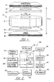
- Fig. 2 illustrates a system 26, which includes ion trap 10, for performing mass spectrometry.
- Ion trap 10 is conventionally mounted in a vacuum chamber 28 with a Channeltron electron multiplier detector 34, manufactured by the Galileo Corp. of Sturbridge, MA.
- Detector 34 is located near the central axis of ion trap 10 to detect the generated ions.
- a Nd:YAG laser source 30 produces a pulsed 266-nm harmonic ( ⁇ 1 mJ/pulse, ⁇ 5 ns duration, 10 Hz repetition rate) beam focussed by a 250 mm lens 32 through a window in vacuum chamber 28 to generate ions within ion trap 10.
- Laser source 30 is a DCR laser made by Quanta Ray Corp. of Mountain View, CA.
- a beam stop (not shown) made from copper tubing is placed near detector 34 to intercept laser light emerging from ion trap 10 to minimize ion generation and photoelectron emission external to trap 10 itself.
- Helium buffer gas at nominally 10 -3 Torr and a sample vapor may be introduced into the vacuum chamber 28 through needle valves (not shown).
- Ion trap 10 is operated in the mass-selective instability mode, with or without a supplementary dipole field for resonant enhancement of the ejection process.
- a conventional computer 36 provides control signals to amplitude modulator 38, a DC345 device manufactured by Stanford Research Systems of Sunnyvale, CA.
- a conventional frequency generator 40 implemented with a DC345 device manufactured by Stanford Research Systems, receives signals from amplitude modulator 38, and outputs the desired trapping voltage and ramp for mass scanning.
- the output signal from frequency generator 40 is then amplified by a 150 W power amplifier 42, the 150A100A amplifier manufactured by Amplifier Research of Souderton, PA., and is applied to ring electrode 12.
- a supplementary voltage from frequency generator 44 may be applied to end caps 14 and 16.
- the output of frequency generator 44 is delivered to a conventional RF amplifier phase inverter 46 before delivery to end caps 14 and 16.
- end caps 14 and 16 are grounded.
- the Channeltron detector's bias voltage up to 1700 V, is supplied by DC power supply 48, the BHK-2000-0 1 MG manufactured by Kepco Corp. of Flushing, NY.
- DC power supply 48 may be programmed so that the detector's bias voltage is reduced during the laser pulse to avoid detector preamplifier overload.
- the output from detector 34 is amplified by current-to-voltage preamplifier 52, an SR570 manufactured by Stanford Research Systems, with a gain of 50-200 nA V -1 and stored on digital oscilloscope 50, a TDS 420A manufactured by Tektronix Corp. of Wilsonville, OR.
- ion trap 10 described above was machined using conventional materials and methods, and may be produced with any suitable material and method of manufacture. Moreover, those skilled in the art understand that ion trap 10 may be manufactured into versions that could be integrated with other microscale instrumentation.
- ions are generated with ion trap 10 by employing a laser ionization source 30; however, in an alternative embodiment, electron impact (EI) ionization may be employed.
- EI electron impact
- An EI source can generate ions from atomic or molecular species that are difficult to ionize with laser pulses.
- EI source When employing an EI source, it is preferably located within the vacuum chamber 28, which houses ion trap 10. This permits the EI source, ion trap 10, and detector 34 to be self-contained, and therefore, much smaller in overall size than when the external pulsed laser 30 is used. Employing this self-contained arrangement minimizes mass spectrometer size. The size of the ion trap 10 and the associated sampling and detecting components are compatible with micromachining capabilities.
- ion trap 10 any ion production method that works with a laboratory instrument could be used with ion trap 10.
- electrospray ionization or matrix-assisted laser desorption/ionization (MALDI) could be used most notably for large molecules such as biomolecules.
- MALDI matrix-assisted laser desorption/ionization
- Chemical ionization and other forms of charge exchange are also suitable methods of sample ionization.
- ion trap 10 has been described as having a generally tubular shape, and bounding a partially enclosed cavity with a corresponding cylindrical shape.
- other conventional ion trap geometries could be employed while maintaining a submillimeter ion trap, as described, namely one having a z o /r o ratio greater than 0.83.
- an average effective r o could be used for z o /r o determination.
- an average effective length 2z o could be employed for ratio determination.
Landscapes
- Chemical & Material Sciences (AREA)
- Analytical Chemistry (AREA)
- Other Investigation Or Analysis Of Materials By Electrical Means (AREA)
- Electron Tubes For Measurement (AREA)
Claims (10)
- Ionenfallen-Massenspektrometer (10) zur chemischen Analyse, umfassend:a) eine zentrale Elektrode (12) mit einer Öffnung;b) ein Paar Isolatoren (18,20), wobei jeder eine Öffnung aufweist;c) ein Paar Endkappenelektroden (14, 16), wobei jeder eine Öffnung aufweist;d) eine erste elektronische Signalquelle (40), die an die zentrale Elektrode gekoppelt ist; unde) eine zweite elektronische Signalquelle (44), die an die Endkappenelektroden gekoppelt ist;f) wobei die zentrale Elektrode, die Isolatoren und die Endkappenelektroden sandwichartig vereint sind, wobei deren jeweiligen Öffnungen koaxial ausgerichtet und symmetrisch zu einer Achse angeordnet sind und dabei einen teilweise gekapselten Hohlraum mit einem effektiven Radius r0 und mit einer effektiven Länge 2z0 bilden, wobei mindestens einer der beiden r0 und z0 weniger als 1,0 mm beträgt und das Verhältnis z0/r0 größer ist als 0,83.
- Ionenfalle nach Anspruch 1, wobei die zentrale Elektrode (12) ringförmig ist.
- Ionenfalle nach Anspruch 1, wobei der Hohlraum zylinderförmig ist.
- Ionenfalle nach Anspruch 1, wobei die effektive Länge 2z0 den Abstand zwischen einander gegenüberliegenden Innenflächen der Endkappenelektroden aufweist.
- Ionenfalle nach Anspruch 1, wobei r0 und z0 beide weniger als 1,0 mm betragen.
- Ionenfalle nach Anspruch 1, wobei die lonisationsquelle eine Laserstrahlquelle (30) aufweist.
- Ionenfalle nach Anspruch 1, wobei die lonisationsquelle eine Elektronenstoß (EI) lonisationsquelle aufweist.
- Ionenfalle nach Anspruch 1, wobei die zentrale Elektrode unter Verwendung eines dotierten Halbleitermaterials hergestellt ist.
- Ionenfalle nach Anspruch 1, wobei die Endkappenelektroden unter Verwendung eines dotierten Halbleitermaterials hergestellt sind.
- Ionenfalle nach Anspruch 1, wobei die Isolatoren unter Verwendung einer Folie bestehend aus einem Werkstoff ausgewählt aus der Gruppe bestehend aus Kunststoff, Keramik und Glas hergestellt sind.
Applications Claiming Priority (3)
| Application Number | Priority Date | Filing Date | Title |
|---|---|---|---|
| US09/398,702 US6469298B1 (en) | 1999-09-20 | 1999-09-20 | Microscale ion trap mass spectrometer |
| US398702 | 1999-09-20 | ||
| PCT/US2000/025951 WO2001022079A2 (en) | 1999-09-20 | 2000-09-20 | Microscale ion trap mass spectrometer |
Publications (2)
| Publication Number | Publication Date |
|---|---|
| EP1218921A2 EP1218921A2 (de) | 2002-07-03 |
| EP1218921B1 true EP1218921B1 (de) | 2008-06-11 |
Family
ID=23576451
Family Applications (1)
| Application Number | Title | Priority Date | Filing Date |
|---|---|---|---|
| EP00965271A Expired - Lifetime EP1218921B1 (de) | 1999-09-20 | 2000-09-20 | Miniaturisierter ionenfalle-massenspektrometer |
Country Status (8)
| Country | Link |
|---|---|
| US (1) | US6469298B1 (de) |
| EP (1) | EP1218921B1 (de) |
| JP (1) | JP3704705B2 (de) |
| AT (1) | ATE398335T1 (de) |
| AU (1) | AU7601200A (de) |
| CA (1) | CA2388748C (de) |
| DE (1) | DE60039178D1 (de) |
| WO (1) | WO2001022079A2 (de) |
Families Citing this family (35)
| Publication number | Priority date | Publication date | Assignee | Title |
|---|---|---|---|---|
| JP3752458B2 (ja) * | 2002-02-18 | 2006-03-08 | 株式会社日立ハイテクノロジーズ | 質量分析装置 |
| CA2507834C (en) * | 2002-12-02 | 2009-09-29 | Griffin Analytical Technologies, Inc. | Processes for designing mass separators and ion traps, methods for producing mass separators and ion traps, mass spectrometers, ion traps, and methods for analyzing samples |
| JP3936908B2 (ja) * | 2002-12-24 | 2007-06-27 | 株式会社日立ハイテクノロジーズ | 質量分析装置及び質量分析方法 |
| US7081623B2 (en) * | 2003-09-05 | 2006-07-25 | Lucent Technologies Inc. | Wafer-based ion traps |
| US6933498B1 (en) * | 2004-03-16 | 2005-08-23 | Ut-Battelle, Llc | Ion trap array-based systems and methods for chemical analysis |
| WO2006002027A2 (en) | 2004-06-15 | 2006-01-05 | Griffin Analytical Technologies, Inc. | Portable mass spectrometer configured to perform multidimensional mass analysis |
| US7012250B1 (en) | 2004-12-03 | 2006-03-14 | Lucent Technologies Inc. | Wafer supported, out-of-plane ion trap devices |
| US7217922B2 (en) * | 2005-03-14 | 2007-05-15 | Lucent Technologies Inc. | Planar micro-miniature ion trap devices |
| US7276689B2 (en) * | 2005-03-25 | 2007-10-02 | Lucent Technologies Inc. | Apparatus for trapping uncharged multi-pole particles |
| CN101317246A (zh) | 2005-04-25 | 2008-12-03 | 格里芬分析技术有限责任公司 | 分析仪器、装置和方法 |
| US7411187B2 (en) | 2005-05-23 | 2008-08-12 | The Regents Of The University Of Michigan | Ion trap in a semiconductor chip |
| US20060275537A1 (en) * | 2005-06-02 | 2006-12-07 | The Regents Of The University Of California | Method and apparatus for field-emission high-pressure-discharge laser chemical vapor deposition of free-standing structures |
| US7992424B1 (en) | 2006-09-14 | 2011-08-09 | Griffin Analytical Technologies, L.L.C. | Analytical instrumentation and sample analysis methods |
| US7767959B1 (en) * | 2007-05-21 | 2010-08-03 | Northrop Grumman Corporation | Miniature mass spectrometer for the analysis of chemical and biological solid samples |
| US8334506B2 (en) | 2007-12-10 | 2012-12-18 | 1St Detect Corporation | End cap voltage control of ion traps |
| US7973277B2 (en) | 2008-05-27 | 2011-07-05 | 1St Detect Corporation | Driving a mass spectrometer ion trap or mass filter |
| US8309912B2 (en) * | 2008-11-21 | 2012-11-13 | Applied Nanotech Holdings, Inc. | Atmospheric pressure ion trap |
| US8835840B1 (en) * | 2009-09-18 | 2014-09-16 | Washington State University | Positron storage micro-trap array |
| WO2014105089A1 (en) | 2012-12-31 | 2014-07-03 | 908 Devices Inc. | Compact mass spectrometer |
| US9093253B2 (en) | 2012-12-31 | 2015-07-28 | 908 Devices Inc. | High pressure mass spectrometry systems and methods |
| US8525111B1 (en) | 2012-12-31 | 2013-09-03 | 908 Devices Inc. | High pressure mass spectrometry systems and methods |
| US9099286B2 (en) | 2012-12-31 | 2015-08-04 | 908 Devices Inc. | Compact mass spectrometer |
| US9373492B2 (en) * | 2013-03-14 | 2016-06-21 | The University Of North Carolina At Chapel Hill | Microscale mass spectrometry systems, devices and related methods |
| US8878127B2 (en) | 2013-03-15 | 2014-11-04 | The University Of North Carolina Of Chapel Hill | Miniature charged particle trap with elongated trapping region for mass spectrometry |
| EP3094958B1 (de) | 2014-01-14 | 2023-07-12 | 908 Devices Inc. | Probenentnahme bei kompakten massenspektrometriesystemen |
| US8816272B1 (en) | 2014-05-02 | 2014-08-26 | 908 Devices Inc. | High pressure mass spectrometry systems and methods |
| US8921774B1 (en) | 2014-05-02 | 2014-12-30 | 908 Devices Inc. | High pressure mass spectrometry systems and methods |
| US9711341B2 (en) * | 2014-06-10 | 2017-07-18 | The University Of North Carolina At Chapel Hill | Mass spectrometry systems with convective flow of buffer gas for enhanced signals and related methods |
| CN106165060B (zh) * | 2014-08-15 | 2018-07-06 | 中国计量科学研究院 | 一种新型矩形离子阱装置及存储与分离离子的方法 |
| US9406492B1 (en) * | 2015-05-12 | 2016-08-02 | The University Of North Carolina At Chapel Hill | Electrospray ionization interface to high pressure mass spectrometry and related methods |
| WO2017079193A1 (en) | 2015-11-02 | 2017-05-11 | Purdue Research Foundation | Precurson and neutral loss scan in an ion trap |
| US10253624B2 (en) | 2016-10-05 | 2019-04-09 | Schlumberger Technology Corporation | Methods of applications for a mass spectrometer in combination with a gas chromatograph |
| US9932825B1 (en) | 2016-10-05 | 2018-04-03 | Schlumberger Technology Corporation | Gas chromatograph mass spectrometer for downhole applications |
| US10242857B2 (en) | 2017-08-31 | 2019-03-26 | The University Of North Carolina At Chapel Hill | Ion traps with Y-directional ion manipulation for mass spectrometry and related mass spectrometry systems and methods |
| EP3895201A4 (de) * | 2018-12-13 | 2022-08-10 | Perkinelmer Health Sciences Canada, Inc | Massenspektrometerkomponenten mit programmierbaren elementen sowie vorrichtungen und systeme damit |
Family Cites Families (6)
| Publication number | Priority date | Publication date | Assignee | Title |
|---|---|---|---|---|
| DE3880456D1 (de) | 1987-12-23 | 1993-05-27 | Bruker Franzen Analytik Gmbh | Verfahren zur massenspektroskopischen untersuchung eines gasgemisches und massenspektrometer zur durchfuehrung dieses verfahrens. |
| DE3886922T2 (de) | 1988-04-13 | 1994-04-28 | Bruker Franzen Analytik Gmbh | Methode zur Massenanalyse einer Probe mittels eines Quistors und zur Durchführung dieses Verfahrens entwickelter Quistor. |
| ATE101942T1 (de) | 1989-02-18 | 1994-03-15 | Bruker Franzen Analytik Gmbh | Verfahren und geraet zur massenbestimmung von proben mittels eines quistors. |
| US5248883A (en) | 1991-05-30 | 1993-09-28 | International Business Machines Corporation | Ion traps of mono- or multi-planar geometry and planar ion trap devices |
| US5386115A (en) | 1993-09-22 | 1995-01-31 | Westinghouse Electric Corporation | Solid state micro-machined mass spectrograph universal gas detection sensor |
| JP3617662B2 (ja) * | 1997-02-28 | 2005-02-09 | 株式会社島津製作所 | 質量分析装置 |
-
1999
- 1999-09-20 US US09/398,702 patent/US6469298B1/en not_active Expired - Lifetime
-
2000
- 2000-09-20 CA CA002388748A patent/CA2388748C/en not_active Expired - Fee Related
- 2000-09-20 DE DE60039178T patent/DE60039178D1/de not_active Expired - Lifetime
- 2000-09-20 EP EP00965271A patent/EP1218921B1/de not_active Expired - Lifetime
- 2000-09-20 WO PCT/US2000/025951 patent/WO2001022079A2/en not_active Ceased
- 2000-09-20 AT AT00965271T patent/ATE398335T1/de not_active IP Right Cessation
- 2000-09-20 AU AU76012/00A patent/AU7601200A/en not_active Abandoned
- 2000-09-20 JP JP2001525200A patent/JP3704705B2/ja not_active Expired - Lifetime
Also Published As
| Publication number | Publication date |
|---|---|
| CA2388748A1 (en) | 2001-03-29 |
| JP2003510760A (ja) | 2003-03-18 |
| AU7601200A (en) | 2001-04-24 |
| ATE398335T1 (de) | 2008-07-15 |
| CA2388748C (en) | 2005-04-26 |
| WO2001022079A3 (en) | 2001-10-18 |
| EP1218921A2 (de) | 2002-07-03 |
| WO2001022079A2 (en) | 2001-03-29 |
| JP3704705B2 (ja) | 2005-10-12 |
| DE60039178D1 (de) | 2008-07-24 |
| US6469298B1 (en) | 2002-10-22 |
Similar Documents
| Publication | Publication Date | Title |
|---|---|---|
| EP1218921B1 (de) | Miniaturisierter ionenfalle-massenspektrometer | |
| US6933498B1 (en) | Ion trap array-based systems and methods for chemical analysis | |
| TWI484529B (zh) | 離子阱質譜儀、利用其得到質譜之方法、離子阱、捕捉離子阱內之離子之方法和設備 | |
| JP6748755B2 (ja) | 小型質量分析器を用いたサンプル定量化 | |
| Badman et al. | A parallel miniature cylindrical ion trap array | |
| Kornienko et al. | Micro ion trap mass spectrometry | |
| US6750448B2 (en) | Preparative separation of mixtures by mass spectrometry | |
| EP0103586B1 (de) | Durch zerstäubung induzierte resonanz-ionisierungsspektrometrie | |
| US7329864B2 (en) | Mass spectrometry with multiple ionization sources and multiple mass analyzers | |
| US5852295A (en) | Ion source for compact mass spectrometer and method of mass analyzing a sample | |
| US7109478B2 (en) | Method and apparatus for automating an atmospheric pressure ionization (API) source for mass spectrometry | |
| EP1721330A2 (de) | Fokalebenen-detektorbaugruppe eines massenspektrometers | |
| US20240347332A1 (en) | Mass Spectrometer Components Including Programmable Elements and Devices and Systems Using Them | |
| EP0878828A1 (de) | Hochdruckionenquelle für ein zweidimensionales Radiofrequenzquadrupolmassenspektrometer | |
| Chambers et al. | Development of an ion store/time-of-flight mass spectrometer for the analysis of volatile compounds in air | |
| JP3300602B2 (ja) | 大気圧イオン化イオントラップ質量分析方法及び装置 | |
| Westman-Brinkmalm et al. | A mass spectrometer's building blocks | |
| Wait | Introduction to mass spectrometry | |
| Hill et al. | Fast neutral beam ion source coupled to a Fourier transform ion cyclotron resonance mass spectrometer | |
| Jude et al. | High-Resolution Mass Spectrometry: Instrumentation in General | |
| Oser et al. | Low-noise ion source for the implementation of Jet-REMPI: novel on-line monitor for process control | |
| BHATIA | DEVELOPMENT OF MAGNETIC SECTOR MASS SPECTROMETERS FOR ISOTOPIC RATIO ANALYSIS | |
| Whitten et al. | Microchip ion trap mass spectrometry | |
| Chambers et al. | Ion storage techniques and time-of-flight mass spectrometry in physical forensic science | |
| Buttrill Jr | Investigation of Mechanisms in Field-Desorbed Ion Formation Using a Pulsed Field Desorption Time-of-Flight Mass Spectrometer. |
Legal Events
| Date | Code | Title | Description |
|---|---|---|---|
| PUAI | Public reference made under article 153(3) epc to a published international application that has entered the european phase |
Free format text: ORIGINAL CODE: 0009012 |
|
| 17P | Request for examination filed |
Effective date: 20020422 |
|
| AK | Designated contracting states |
Kind code of ref document: A2 Designated state(s): AT BE CH CY DE DK ES FI FR GB GR IE IT LI LU MC NL PT SE |
|
| AX | Request for extension of the european patent |
Free format text: AL;LT;LV;MK;RO;SI |
|
| GRAP | Despatch of communication of intention to grant a patent |
Free format text: ORIGINAL CODE: EPIDOSNIGR1 |
|
| GRAS | Grant fee paid |
Free format text: ORIGINAL CODE: EPIDOSNIGR3 |
|
| GRAA | (expected) grant |
Free format text: ORIGINAL CODE: 0009210 |
|
| AK | Designated contracting states |
Kind code of ref document: B1 Designated state(s): AT BE CH CY DE DK ES FI FR GB GR IE IT LI LU MC NL PT SE |
|
| REG | Reference to a national code |
Ref country code: GB Ref legal event code: FG4D |
|
| REG | Reference to a national code |
Ref country code: CH Ref legal event code: EP |
|
| REF | Corresponds to: |
Ref document number: 60039178 Country of ref document: DE Date of ref document: 20080724 Kind code of ref document: P |
|
| REG | Reference to a national code |
Ref country code: IE Ref legal event code: FG4D |
|
| PG25 | Lapsed in a contracting state [announced via postgrant information from national office to epo] |
Ref country code: FI Free format text: LAPSE BECAUSE OF FAILURE TO SUBMIT A TRANSLATION OF THE DESCRIPTION OR TO PAY THE FEE WITHIN THE PRESCRIBED TIME-LIMIT Effective date: 20080611 |
|
| PG25 | Lapsed in a contracting state [announced via postgrant information from national office to epo] |
Ref country code: NL Free format text: LAPSE BECAUSE OF FAILURE TO SUBMIT A TRANSLATION OF THE DESCRIPTION OR TO PAY THE FEE WITHIN THE PRESCRIBED TIME-LIMIT Effective date: 20080611 Ref country code: AT Free format text: LAPSE BECAUSE OF FAILURE TO SUBMIT A TRANSLATION OF THE DESCRIPTION OR TO PAY THE FEE WITHIN THE PRESCRIBED TIME-LIMIT Effective date: 20080611 |
|
| NLV1 | Nl: lapsed or annulled due to failure to fulfill the requirements of art. 29p and 29m of the patents act | ||
| PG25 | Lapsed in a contracting state [announced via postgrant information from national office to epo] |
Ref country code: PT Free format text: LAPSE BECAUSE OF FAILURE TO SUBMIT A TRANSLATION OF THE DESCRIPTION OR TO PAY THE FEE WITHIN THE PRESCRIBED TIME-LIMIT Effective date: 20081111 Ref country code: SE Free format text: LAPSE BECAUSE OF FAILURE TO SUBMIT A TRANSLATION OF THE DESCRIPTION OR TO PAY THE FEE WITHIN THE PRESCRIBED TIME-LIMIT Effective date: 20080911 Ref country code: ES Free format text: LAPSE BECAUSE OF FAILURE TO SUBMIT A TRANSLATION OF THE DESCRIPTION OR TO PAY THE FEE WITHIN THE PRESCRIBED TIME-LIMIT Effective date: 20080922 |
|
| PG25 | Lapsed in a contracting state [announced via postgrant information from national office to epo] |
Ref country code: BE Free format text: LAPSE BECAUSE OF FAILURE TO SUBMIT A TRANSLATION OF THE DESCRIPTION OR TO PAY THE FEE WITHIN THE PRESCRIBED TIME-LIMIT Effective date: 20080611 |
|
| PLBE | No opposition filed within time limit |
Free format text: ORIGINAL CODE: 0009261 |
|
| STAA | Information on the status of an ep patent application or granted ep patent |
Free format text: STATUS: NO OPPOSITION FILED WITHIN TIME LIMIT |
|
| PG25 | Lapsed in a contracting state [announced via postgrant information from national office to epo] |
Ref country code: MC Free format text: LAPSE BECAUSE OF NON-PAYMENT OF DUE FEES Effective date: 20080930 Ref country code: DK Free format text: LAPSE BECAUSE OF FAILURE TO SUBMIT A TRANSLATION OF THE DESCRIPTION OR TO PAY THE FEE WITHIN THE PRESCRIBED TIME-LIMIT Effective date: 20080611 |
|
| REG | Reference to a national code |
Ref country code: CH Ref legal event code: PL |
|
| 26N | No opposition filed |
Effective date: 20090312 |
|
| REG | Reference to a national code |
Ref country code: IE Ref legal event code: MM4A |
|
| PG25 | Lapsed in a contracting state [announced via postgrant information from national office to epo] |
Ref country code: IE Free format text: LAPSE BECAUSE OF NON-PAYMENT OF DUE FEES Effective date: 20080920 |
|
| PG25 | Lapsed in a contracting state [announced via postgrant information from national office to epo] |
Ref country code: CH Free format text: LAPSE BECAUSE OF NON-PAYMENT OF DUE FEES Effective date: 20080930 Ref country code: LI Free format text: LAPSE BECAUSE OF NON-PAYMENT OF DUE FEES Effective date: 20080930 |
|
| PG25 | Lapsed in a contracting state [announced via postgrant information from national office to epo] |
Ref country code: LU Free format text: LAPSE BECAUSE OF NON-PAYMENT OF DUE FEES Effective date: 20080920 Ref country code: CY Free format text: LAPSE BECAUSE OF FAILURE TO SUBMIT A TRANSLATION OF THE DESCRIPTION OR TO PAY THE FEE WITHIN THE PRESCRIBED TIME-LIMIT Effective date: 20080611 |
|
| PG25 | Lapsed in a contracting state [announced via postgrant information from national office to epo] |
Ref country code: GR Free format text: LAPSE BECAUSE OF FAILURE TO SUBMIT A TRANSLATION OF THE DESCRIPTION OR TO PAY THE FEE WITHIN THE PRESCRIBED TIME-LIMIT Effective date: 20080912 |
|
| PGFP | Annual fee paid to national office [announced via postgrant information from national office to epo] |
Ref country code: IT Payment date: 20100924 Year of fee payment: 11 |
|
| PGFP | Annual fee paid to national office [announced via postgrant information from national office to epo] |
Ref country code: FR Payment date: 20101013 Year of fee payment: 11 |
|
| PG25 | Lapsed in a contracting state [announced via postgrant information from national office to epo] |
Ref country code: IT Free format text: LAPSE BECAUSE OF NON-PAYMENT OF DUE FEES Effective date: 20110920 |
|
| REG | Reference to a national code |
Ref country code: FR Ref legal event code: ST Effective date: 20120531 |
|
| PG25 | Lapsed in a contracting state [announced via postgrant information from national office to epo] |
Ref country code: FR Free format text: LAPSE BECAUSE OF NON-PAYMENT OF DUE FEES Effective date: 20110930 |
|
| REG | Reference to a national code |
Ref country code: GB Ref legal event code: S13A Free format text: APPLICATION FILED; APPLICATION FOR A PERSON TO BE MENTIONED AS AN INVENTOR UNDER RULE 10(2) BY UT-BATTELLE, LLC FILED 23 JULY 2012. Ref country code: GB Ref legal event code: S13A Free format text: APPLICATION ALLOWED; IN A DECISION OF THE COMPTROLLER DATED 26 OCTOBER 2012, THE APPLICATION FILED UNDER RULE 10(2) WAS ALLOWED. THE COMPTROLLER FOUND THAT OLEG KORNIENKO SHOULD BE MENTIONED AS A JOINT INVENTOR AND DIRECTED THAT AN ADDENDUM SLIP MENTIONING HIM AS SUCH BE PREPARED FOR THE GRANTED PATENT FOR THE INVENTION. |
|
| PGFP | Annual fee paid to national office [announced via postgrant information from national office to epo] |
Ref country code: DE Payment date: 20190918 Year of fee payment: 20 |
|
| PGFP | Annual fee paid to national office [announced via postgrant information from national office to epo] |
Ref country code: GB Payment date: 20190920 Year of fee payment: 20 |
|
| REG | Reference to a national code |
Ref country code: DE Ref legal event code: R071 Ref document number: 60039178 Country of ref document: DE |
|
| REG | Reference to a national code |
Ref country code: GB Ref legal event code: PE20 Expiry date: 20200919 |
|
| PG25 | Lapsed in a contracting state [announced via postgrant information from national office to epo] |
Ref country code: GB Free format text: LAPSE BECAUSE OF EXPIRATION OF PROTECTION Effective date: 20200919 |