EP1219224A1 - Dispositif pour mouiller et essorer une serpillière - Google Patents
Dispositif pour mouiller et essorer une serpillière Download PDFInfo
- Publication number
- EP1219224A1 EP1219224A1 EP01130430A EP01130430A EP1219224A1 EP 1219224 A1 EP1219224 A1 EP 1219224A1 EP 01130430 A EP01130430 A EP 01130430A EP 01130430 A EP01130430 A EP 01130430A EP 1219224 A1 EP1219224 A1 EP 1219224A1
- Authority
- EP
- European Patent Office
- Prior art keywords
- liquid
- region
- container
- wiping part
- outflow
- Prior art date
- Legal status (The legal status is an assumption and is not a legal conclusion. Google has not performed a legal analysis and makes no representation as to the accuracy of the status listed.)
- Granted
Links
- 238000004062 sedimentation Methods 0.000 claims abstract description 29
- 239000007787 solid Substances 0.000 claims abstract 2
- 239000007788 liquid Substances 0.000 claims description 57
- 238000007791 dehumidification Methods 0.000 claims description 5
- 230000033001 locomotion Effects 0.000 claims description 2
- 238000011144 upstream manufacturing Methods 0.000 claims description 2
- 239000007921 spray Substances 0.000 abstract description 14
- XLYOFNOQVPJJNP-UHFFFAOYSA-N water Substances O XLYOFNOQVPJJNP-UHFFFAOYSA-N 0.000 abstract description 2
- 238000009736 wetting Methods 0.000 abstract 1
- 239000002245 particle Substances 0.000 description 11
- 238000004140 cleaning Methods 0.000 description 9
- 238000000926 separation method Methods 0.000 description 6
- 238000005192 partition Methods 0.000 description 5
- 230000000694 effects Effects 0.000 description 4
- 238000011161 development Methods 0.000 description 3
- 230000018109 developmental process Effects 0.000 description 3
- 238000003825 pressing Methods 0.000 description 3
- 230000002745 absorbent Effects 0.000 description 2
- 239000002250 absorbent Substances 0.000 description 2
- WYTGDNHDOZPMIW-RCBQFDQVSA-N alstonine Natural products C1=CC2=C3C=CC=CC3=NC2=C2N1C[C@H]1[C@H](C)OC=C(C(=O)OC)[C@H]1C2 WYTGDNHDOZPMIW-RCBQFDQVSA-N 0.000 description 2
- 241000446313 Lamella Species 0.000 description 1
- 239000000654 additive Substances 0.000 description 1
- 238000003780 insertion Methods 0.000 description 1
- 230000037431 insertion Effects 0.000 description 1
- 230000007774 longterm Effects 0.000 description 1
- 239000000463 material Substances 0.000 description 1
- 238000000034 method Methods 0.000 description 1
- 230000003287 optical effect Effects 0.000 description 1
- 238000005096 rolling process Methods 0.000 description 1
- 238000007789 sealing Methods 0.000 description 1
- 239000004753 textile Substances 0.000 description 1
Images

Classifications
-
- A—HUMAN NECESSITIES
- A47—FURNITURE; DOMESTIC ARTICLES OR APPLIANCES; COFFEE MILLS; SPICE MILLS; SUCTION CLEANERS IN GENERAL
- A47L—DOMESTIC WASHING OR CLEANING; SUCTION CLEANERS IN GENERAL
- A47L13/00—Implements for cleaning floors, carpets, furniture, walls, or wall coverings
- A47L13/10—Scrubbing; Scouring; Cleaning; Polishing
- A47L13/20—Mops
- A47L13/22—Mops with liquid-feeding devices
-
- A—HUMAN NECESSITIES
- A47—FURNITURE; DOMESTIC ARTICLES OR APPLIANCES; COFFEE MILLS; SPICE MILLS; SUCTION CLEANERS IN GENERAL
- A47L—DOMESTIC WASHING OR CLEANING; SUCTION CLEANERS IN GENERAL
- A47L13/00—Implements for cleaning floors, carpets, furniture, walls, or wall coverings
- A47L13/10—Scrubbing; Scouring; Cleaning; Polishing
- A47L13/50—Auxiliary implements
- A47L13/58—Wringers for scouring pads, mops, or the like, combined with buckets
- A47L13/60—Wringers for scouring pads, mops, or the like, combined with buckets with squeezing rollers
Definitions
- the invention relates to a device for moistening and dehumidifying a wiping part of a damp mop.
- damp mop is used to refer to all cleaning devices that are absorbent
- a wiping part that is soaked in a liquid and in a moist state can be guided over the surfaces or objects to be cleaned.
- a liquid water is generally used with additives if necessary.
- wet wipers are, for example, mops and mop pads that over have a frayed or flat wiping part that is attached to the end of a stem.
- Such wet wipers are usually used together with a container for holding of liquid, the container being mostly a manual dehumidifier with which the wiping part is pressed or wrung out can.
- the damp mop is usually with its wiping part first dipped in the liquid to moisten, then to achieve a desired one for cleaning Moisture partially dehumidified and over the object to be cleaned or led the area to be cleaned. Then the wiping part is immersed in the liquid, in order to rinse out the dirt that has been taken up, the wiping part again is moistened.
- the liquid accumulates in the course of the cleaning process dirt picked up by the wiping part, the wiping part being immersed in the Liquid absorbs part of the dirt every time. Because in this case Wiping part is already dirty before wiping and accordingly a reduced Has a cleaning effect, the liquid is usually exchanged as soon as it has one has absorbed a certain amount of dirt.
- the invention has for its object a device for moistening and dehumidifying to create a wiping part of a damp mop with the given amount of liquid a better cleaning effect can be achieved in the long term.
- One or more impact bodies can form a labyrinth in the inflow area in order to there the Reduce the inflow rate of the liquid and so a smooth flow in the Create sedimentation compartment.
- a baffle can also be used as a baffle Liquid flow area are used in the openings to slow down Passage of the liquid are arranged.
- the separation capacity of the sedimentation compartment is significantly influenced by its size, so that with a large distance between inflow area and outflow area a large sedimentation compartment can be created with a high separation performance.
- the bottom can be over Have depressions in which the dirt can settle better, the depressions in particular formed by grooves running transversely to the direction of flow become.
- the separation of dirt particles can also be increased, for example low partitions are improved that are transverse to the flow direction are arranged between the inflow area and the outflow area.
- the filter effect of the device can be further improved by filters that are in the course the liquid flow up to the inflow area and / or behind the outflow area can be provided in any number.
- the bottom of the sedimentation compartment is removable, cleaning can be essential be simplified, which also removes the deposited dirt without having to drain the liquid from the container.
- the liquid flow can be just before the outflow area from the bottom to the top, so that this Deflection settles dirt and a removable one below the outflow area
- Bottom part can be provided for example in the form of a shell.
- the known manual devices can also be used for dehumidification as long as the resulting liquid through appropriate liquid lines is directed into a defined inflow area of the container.
- Such dehumidifiers can, for example, presses for pressing out wiping pads or mops or openings with tapered truncated cones in which a mop pressed in from above with rotation is wrung out can be.
- the wiping part can be moistened by a pump in a defined manner
- Outflow area of the container takes liquid and directs it to the wiping part.
- the pump can also be set up to manually pressurize it with the damp mop can be actuated.
- the container can also be provided with means that allow the damp mop to be immersed only at a certain point, so that this forms the outflow area.
- Another design option is to arrange an outflow valve below the liquid level on the outside of the container, that is connected to the outflow area inside the container and that from the outside can be opened for example by pressure with the wiping part.
- the moistening device is advantageously a spray nozzle fed by the pump, which can extend essentially transversely to the direction of movement in which the Wiping part can be moved by a drive device.
- the spray nozzle can have a higher and / or stronger discharge of liquid at the edges. Furthermore, the spray nozzle can be swung back and forth during moistening, to increase the mechanical action and thus cleaning effect on the wiping part.
- nozzles arranged side by side and directed against the wiping part be used.
- Another option is to have at least one nozzle to be provided, the beam of which is directed onto a deflection surface which fans out the beam and steers against the wiping part.
- the dehumidification of the wiping part can be arranged above the container Dehumidifying device can be carried out so that the dehumidified liquid if necessary after passing through a filter, directed into an inflow area can be, the dehumidification advantageously by pressing between two Rolling happens that with motor drive also for moving the wiping part can be used.
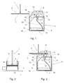
- a damp mop 1 is shown on the left in the form of a wiping pad, which is a carrier plate 2, which is hinged at the bottom to a partially shown stem, the carrier plate 2 below an absorbent wiping part 3, preferably made of textile material having.
- the device has a container 5 for receiving one for cleaning used liquid 6 on.
- the upper opening of the container 5 is one
- the intermediate floor 17 is closed, on which the wiping part 3 necessary components are attached.
- the intermediate floor 17 Above the intermediate floor 17 are guides 13 for the vertical supports Carrier plate 2 and the wiping part 3 and opposing rollers 9, 10 are arranged.
- the lower roller 10 is provided with an elastic covering and with a motor 16 connected to drive in the direction of rotation.
- the distance between the rollers 9, 10 is so dimension that the wiping part 3 together with the carrier plate 2 when passing through pressed together and dehumidified in this way.
- Left of the rollers 9, 10 is furthermore an upwardly directed spray nozzle 12 is arranged which is carried by a pump 8 Liquid 6 can be supplied. With the help of the spray nozzle 12, the wiping part 3 can Passing through the device 4 are rinsed or moistened.
- the guides 13 to the left of the rollers 9, 10 also have a switch 14, which on the Introducing the wiping part 3 and in particular the presence of the wiping part 3 in addresses an area in which at least a portion of the wiping part 3 of the Spray nozzle 12 can be detected.
- the Roller 10 and pump 8 are driven by a single motor. In this case independent control of the spray nozzle 12 can nevertheless be achieved by in a controllable valve is provided for the line feeding the spray nozzle.
- the pump 8 sucks the liquid 6 through a hose 11 in an outflow area 19 from the container 5.
- the lower end of the hose 11 is fixed in the outflow area 19 of the container 5 attached.
- a sedimentation compartment is located between the inflow area 18 and the outflow area 19 7.
- the sedimentation compartment 7 has a removable bottom part, which has grooves that are transverse to the liquid flow direction between the inflow area 18 and outflow region 19 extend.
- the sedimentation compartment 7 will both to the inflow region 18 and to the outflow region 19 from low vertical dividing walls that end below the liquid level and between which the removable bottom part can be used.
- The serves low partition in the area of the inflow area 18 to slow down the inflowing area Liquid 6 so that the liquid 6 flows as evenly as possible flows through the sedimentation compartment 7 to the outflow region 19, around the deposit of dirt particles on the removable bottom part.
- the flow guide surface 22 itself can act as a sedimentation compartment serve by being provided on the surface with depressions in which Deposit dirt particles as the liquid 6 runs down.
- this can be removed Section to be attached to the filter 15 so that it can be cleaned together can be removed with the filter 15.
- Grooves running transversely to the direction of flow may be provided.
- the rollers 9, 10 together is formed with the motor 16 and simultaneously to drive the support plate 2 together with the wiping part 3.
- the roller 10 extends over the entire width of the wiping part 3 and presses the wiping part 3 against the rigid carrier plate 2 as it is passed through, which in turn is supported with its edges against the two pressure rollers 9. Between the two pressure rollers 9 there is a gap in the axial direction through which the stem of Wet mop 1 can be passed.
- the two rollers 9 are coaxial with one another and stored parallel to opposite roll 10.
- Fig. 3 the device is shown in operation.
- the switch 14 is actuated, whereupon both the motor 16 of the drive or Dehumidifier and the pump 8 can be controlled.
- the Pump 8 is sucked in liquid 6 from the outflow area 19 and through the spray nozzle 12 sprayed upwards so that the wiping part is rinsed from below when it is passed over it and is moistened.
- the rollers 9, 10 reached, it is gripped by these rollers 9, 10 and pulled through. It will Wiping part 3 pressed together and the previously injected liquid 6 pressed out.
- the liquid 6 flows on the intermediate floor 17 to the filter 15, through this through and from the flow guide surface 22 into the inflow region 18.
- a control (not shown) of the device 4 is set up such that the pump 8 and the motor 16 of the drive device remains activated for a while, if the switch 14 is no longer activated by the wiping part 3. This ensures that the wiping part 3 together with the carrier plate 2 completely through the device 4 is pulled through. It can also be provided that after the Switch 14 is no longer activated by the wiping part 3, the pump 8 a shorter time remains controlled as the motor 16 of the drive device, since the rear end of the wiping part 3 passes the spray nozzle 12 earlier than the rollers 9, 10.
- FIG. 4 to 7 show further embodiments for the sedimentation compartment 7.
- the sedimentation compartment 7 in FIG. 4 is already undulated in the inflow region 18 has a recess in the outflow region 19, in which the liquid flow first down and then out again in the suction hose 11, so that sedimentation of dirt particles also takes place in this depression.
- FIG. 5 shows a curved perforated plate as the impact body 20 in the inflow region 18. Through its openings, the liquid 6 flows slowly into the sedimentation compartment 7, which consists of an inclined and grooved surface, at the end of a partition is arranged in front of which the dirt particles settle. The liquid 6 flows through the Partition into the outflow area 19.
- a vertical meandering liquid flow is shown, the of partitions 21 in front of the outflow area 19 first from top to bottom and is then led from bottom to top.
- the sedimentation of dirt particles By reversing the flow direction Below the right flow guide plate 21 is the sedimentation of dirt particles in the area between the left flow guide plate 21 and the right wall of the container 5, whereby also in the area on the left of the left flow guide plate 21 dirt particles settle.
- the sedimentation compartment has an inclined one smooth surface, at the end of which is rounded off just before the outflow region 19 Elevation is arranged, by means of which turbulence in the liquid flow is reduced and swirling of already deposited dirt can be prevented.
- the device 4 can also have a removable splash guard, which is the insertion of the damp mop 1 enables, the device 4 can be set up can that a control of the motor 16 and / or the pump 8 only when attached Splash guard.
- the splash guard has a passage with a cross section that the Cross section of the lower part of the damp mop 1 with the wiping part 3 corresponds. to Sealing the gap in the passage can be a seal in the form of rubber lips or Rows of bristles may be provided.
- the roller 10 can move in two opposite directions are driven, each in front of a switch for detecting the wiping part 3 the drive device 9, 10, 16 is arranged, the drive device 9, 10, 16 is set up in such a way that the wiping part 3 detects the wiping part 3 Switch moves to itself, the spray nozzle 12 is only activated when the Switch is activated by the wiping part 3, which is on the same side of the rollers 9, 10 as the spray nozzle 12 is located.
- the wiping part 3 can thus be turned off when the spray nozzle 12 is switched off can be further dehumidified without humidification by passing it from the other side Device 4 is performed.
- the device 4 can be a device for detecting the fill level of the container 5 have.
- the level can be displayed to the outside, so that a Operator can inform himself about the level, with additional under or An optical and / or acoustic signal is emitted if limit values are exceeded can be.
- the detected fill level when controlling the device 4 are taken into account, for example, by operation when the level is too low or too high Level is prevented or the pump 8 at low level with lower performance is operated in order not to lower the level so much during operation.
Landscapes
- Cleaning Implements For Floors, Carpets, Furniture, Walls, And The Like (AREA)
- Drying Of Solid Materials (AREA)
- Treatment Of Fiber Materials (AREA)
Applications Claiming Priority (2)
| Application Number | Priority Date | Filing Date | Title |
|---|---|---|---|
| DE10065370A DE10065370A1 (de) | 2000-12-27 | 2000-12-27 | Vorrichtung zum Befeuchten und Entfeuchten eines Feuchtwischers |
| DE10065370 | 2000-12-27 |
Publications (2)
| Publication Number | Publication Date |
|---|---|
| EP1219224A1 true EP1219224A1 (fr) | 2002-07-03 |
| EP1219224B1 EP1219224B1 (fr) | 2010-03-24 |
Family
ID=7669229
Family Applications (1)
| Application Number | Title | Priority Date | Filing Date |
|---|---|---|---|
| EP01130430A Expired - Lifetime EP1219224B1 (fr) | 2000-12-27 | 2001-12-20 | Dispositif pour mouiller et essorer une serpillière |
Country Status (3)
| Country | Link |
|---|---|
| EP (1) | EP1219224B1 (fr) |
| AT (1) | ATE461649T1 (fr) |
| DE (2) | DE10065370A1 (fr) |
Cited By (6)
| Publication number | Priority date | Publication date | Assignee | Title |
|---|---|---|---|---|
| EP1634525A1 (fr) * | 2004-09-09 | 2006-03-15 | BSH Bosch und Siemens Hausgeräte GmbH | Appareil et procédé pour laver un balai |
| CN110384446A (zh) * | 2018-04-18 | 2019-10-29 | 程志敏 | 一种拖把头清洗座及清洗桶 |
| CN110833365A (zh) * | 2018-08-15 | 2020-02-25 | 程志敏 | 一种平拖把及使用平拖把的清洁工具 |
| EP3682786A1 (fr) * | 2019-01-18 | 2020-07-22 | Jemako Produktionsgesellschaft mbH | Dispositif de nettoyage de surfaces |
| US12042109B2 (en) | 2018-05-29 | 2024-07-23 | Unger Marketing International, Llc | Flat headed mop and method of operation |
| US12048404B2 (en) | 2019-12-11 | 2024-07-30 | Unger Marketing International, Llc | Floor cleaning system, flat headed mop and mop pad |
Families Citing this family (3)
| Publication number | Priority date | Publication date | Assignee | Title |
|---|---|---|---|---|
| DE10228384A1 (de) * | 2002-06-25 | 2004-01-29 | BSH Bosch und Siemens Hausgeräte GmbH | Verfahren und Vorrichtung zum Aufnehmen von Schmutz von einer Fläche mittels eines Wischtuchs |
| USD915703S1 (en) | 2019-05-28 | 2021-04-06 | Unger Marketng International, Llc | Flat headed mop |
| USD923896S1 (en) | 2019-05-28 | 2021-06-29 | Unger Marketing International, Llc | Floor cleaning system |
Citations (3)
| Publication number | Priority date | Publication date | Assignee | Title |
|---|---|---|---|---|
| US3630369A (en) * | 1970-05-15 | 1971-12-28 | Cecil Patrick Nichols | Mop cleaning device |
| FR2187266A1 (fr) * | 1972-06-07 | 1974-01-18 | Hubner Gustav | |
| US4161799A (en) * | 1974-04-18 | 1979-07-24 | Sorrells Weldon B | Mop cleaning device |
Family Cites Families (2)
| Publication number | Priority date | Publication date | Assignee | Title |
|---|---|---|---|---|
| SE506722C2 (sv) * | 1993-01-26 | 1998-02-02 | Electrolux Ab | Press för moppgarn |
| EP1022976A1 (fr) * | 1995-09-22 | 2000-08-02 | McLaughlin, Hugh Rogers | Appareil pour chasser le liquide d'un balai-eponge |
-
2000
- 2000-12-27 DE DE10065370A patent/DE10065370A1/de not_active Withdrawn
-
2001
- 2001-12-20 DE DE50115403T patent/DE50115403D1/de not_active Expired - Lifetime
- 2001-12-20 EP EP01130430A patent/EP1219224B1/fr not_active Expired - Lifetime
- 2001-12-20 AT AT01130430T patent/ATE461649T1/de not_active IP Right Cessation
Patent Citations (3)
| Publication number | Priority date | Publication date | Assignee | Title |
|---|---|---|---|---|
| US3630369A (en) * | 1970-05-15 | 1971-12-28 | Cecil Patrick Nichols | Mop cleaning device |
| FR2187266A1 (fr) * | 1972-06-07 | 1974-01-18 | Hubner Gustav | |
| US4161799A (en) * | 1974-04-18 | 1979-07-24 | Sorrells Weldon B | Mop cleaning device |
Cited By (7)
| Publication number | Priority date | Publication date | Assignee | Title |
|---|---|---|---|---|
| EP1634525A1 (fr) * | 2004-09-09 | 2006-03-15 | BSH Bosch und Siemens Hausgeräte GmbH | Appareil et procédé pour laver un balai |
| CN110384446A (zh) * | 2018-04-18 | 2019-10-29 | 程志敏 | 一种拖把头清洗座及清洗桶 |
| US12042109B2 (en) | 2018-05-29 | 2024-07-23 | Unger Marketing International, Llc | Flat headed mop and method of operation |
| US12096898B2 (en) | 2018-05-29 | 2024-09-24 | Unger Marketing International, Llc | Floor cleaning system |
| CN110833365A (zh) * | 2018-08-15 | 2020-02-25 | 程志敏 | 一种平拖把及使用平拖把的清洁工具 |
| EP3682786A1 (fr) * | 2019-01-18 | 2020-07-22 | Jemako Produktionsgesellschaft mbH | Dispositif de nettoyage de surfaces |
| US12048404B2 (en) | 2019-12-11 | 2024-07-30 | Unger Marketing International, Llc | Floor cleaning system, flat headed mop and mop pad |
Also Published As
| Publication number | Publication date |
|---|---|
| EP1219224B1 (fr) | 2010-03-24 |
| DE50115403D1 (de) | 2010-05-06 |
| ATE461649T1 (de) | 2010-04-15 |
| DE10065370A1 (de) | 2002-07-04 |
Similar Documents
| Publication | Publication Date | Title |
|---|---|---|
| EP1219226B1 (fr) | Dispositif pour mouiller et essorer une serpillière | |
| EP0593521B1 (fr) | Nettoyeur mobile de sols | |
| WO2017153598A1 (fr) | Nouveau dispositif de nettoyage et procédé de nettoyage | |
| EP1219224B1 (fr) | Dispositif pour mouiller et essorer une serpillière | |
| EP2823746B1 (fr) | Dispositif de nettoyage pour le nettoyage humide des sols | |
| DE2806681C2 (de) | Teppichentwässerungsgerät | |
| DE10228383B4 (de) | Vorrichtung zum Reinigen eines Wischteils eines Feuchtwischers | |
| DE60318708T2 (de) | Tragbare oberflächenbehandlungsvorrichtung | |
| EP1219225B1 (fr) | Dispositif d'humidification des serpillières | |
| DE1922651A1 (de) | Pflegegeraet fuer Fussbodenbelaege | |
| EP0319853A2 (fr) | Procédé et dispositif de filtrage d'impuretés d'un gaz | |
| DE3026923C2 (de) | Vorrichtung zum Behandeln von Filtermaterial | |
| DE2051478A1 (de) | Verfahren und Vorrichtung zum Reim gen von loser Rohwolle | |
| WO2008138767A1 (fr) | Dispositif de traitement, de façonnage et de nettoyage de surfaces | |
| DE1503864B2 (de) | Verfahren, maschine und vorrichtung zum reinigen von bodenbelaegen | |
| DE4303753A1 (de) | Lackiereinrichtung | |
| EP3925508B1 (fr) | Serpillière | |
| DE3309636A1 (de) | Reinigungsautomat | |
| EP1634525B1 (fr) | Appareil et procédé pour laver un balai | |
| DE1503864C (de) | Verfahren, Maschine und Vorrichtung zum Reinigen von Bodenbelägen | |
| DE102004044041A1 (de) | Vorrichtung zum Entfeuchten oder Befeuchten eines Feuchtwischers | |
| EP1120252A2 (fr) | Dispositif de rinçage d'une station d'engommage dans une ensemble de lavage, d'engommage et de séchage de plaques d'impression | |
| DE1546677C (de) | Vorrichtung zur Reinigung eines Gasstromes | |
| DE8008998U1 (de) | Vorrichtung zum auswachsen durchlaessiger warenbahnen | |
| DE8307859U1 (de) | Reinigungsautomat |
Legal Events
| Date | Code | Title | Description |
|---|---|---|---|
| PUAI | Public reference made under article 153(3) epc to a published international application that has entered the european phase |
Free format text: ORIGINAL CODE: 0009012 |
|
| AK | Designated contracting states |
Kind code of ref document: A1 Designated state(s): AT BE CH CY DE DK ES FI FR GB GR IE IT LI LU MC NL PT SE TR |
|
| AX | Request for extension of the european patent |
Free format text: AL;LT;LV;MK;RO;SI |
|
| 17P | Request for examination filed |
Effective date: 20030103 |
|
| AKX | Designation fees paid |
Designated state(s): AT BE CH CY DE DK ES FI FR GB GR IE IT LI LU MC NL PT SE TR |
|
| RAP1 | Party data changed (applicant data changed or rights of an application transferred) |
Owner name: BSH BOSCH UND SIEMENS HAUSGERAETE GMBH |
|
| 17Q | First examination report despatched |
Effective date: 20050704 |
|
| 17Q | First examination report despatched |
Effective date: 20050704 |
|
| GRAP | Despatch of communication of intention to grant a patent |
Free format text: ORIGINAL CODE: EPIDOSNIGR1 |
|
| GRAS | Grant fee paid |
Free format text: ORIGINAL CODE: EPIDOSNIGR3 |
|
| GRAA | (expected) grant |
Free format text: ORIGINAL CODE: 0009210 |
|
| AK | Designated contracting states |
Kind code of ref document: B1 Designated state(s): AT BE CH CY DE DK ES FI FR GB GR IE IT LI LU MC NL PT SE TR |
|
| REG | Reference to a national code |
Ref country code: GB Ref legal event code: FG4D Free format text: NOT ENGLISH |
|
| REG | Reference to a national code |
Ref country code: CH Ref legal event code: EP |
|
| REG | Reference to a national code |
Ref country code: IE Ref legal event code: FG4D |
|
| REF | Corresponds to: |
Ref document number: 50115403 Country of ref document: DE Date of ref document: 20100506 Kind code of ref document: P |
|
| REG | Reference to a national code |
Ref country code: NL Ref legal event code: VDEP Effective date: 20100324 |
|
| PG25 | Lapsed in a contracting state [announced via postgrant information from national office to epo] |
Ref country code: FI Free format text: LAPSE BECAUSE OF FAILURE TO SUBMIT A TRANSLATION OF THE DESCRIPTION OR TO PAY THE FEE WITHIN THE PRESCRIBED TIME-LIMIT Effective date: 20100324 |
|
| REG | Reference to a national code |
Ref country code: IE Ref legal event code: FD4D |
|
| PG25 | Lapsed in a contracting state [announced via postgrant information from national office to epo] |
Ref country code: SE Free format text: LAPSE BECAUSE OF FAILURE TO SUBMIT A TRANSLATION OF THE DESCRIPTION OR TO PAY THE FEE WITHIN THE PRESCRIBED TIME-LIMIT Effective date: 20100324 Ref country code: NL Free format text: LAPSE BECAUSE OF FAILURE TO SUBMIT A TRANSLATION OF THE DESCRIPTION OR TO PAY THE FEE WITHIN THE PRESCRIBED TIME-LIMIT Effective date: 20100324 Ref country code: GR Free format text: LAPSE BECAUSE OF FAILURE TO SUBMIT A TRANSLATION OF THE DESCRIPTION OR TO PAY THE FEE WITHIN THE PRESCRIBED TIME-LIMIT Effective date: 20100625 Ref country code: ES Free format text: LAPSE BECAUSE OF FAILURE TO SUBMIT A TRANSLATION OF THE DESCRIPTION OR TO PAY THE FEE WITHIN THE PRESCRIBED TIME-LIMIT Effective date: 20100705 |
|
| PLBE | No opposition filed within time limit |
Free format text: ORIGINAL CODE: 0009261 |
|
| STAA | Information on the status of an ep patent application or granted ep patent |
Free format text: STATUS: NO OPPOSITION FILED WITHIN TIME LIMIT |
|
| PG25 | Lapsed in a contracting state [announced via postgrant information from national office to epo] |
Ref country code: IE Free format text: LAPSE BECAUSE OF FAILURE TO SUBMIT A TRANSLATION OF THE DESCRIPTION OR TO PAY THE FEE WITHIN THE PRESCRIBED TIME-LIMIT Effective date: 20100324 Ref country code: PT Free format text: LAPSE BECAUSE OF FAILURE TO SUBMIT A TRANSLATION OF THE DESCRIPTION OR TO PAY THE FEE WITHIN THE PRESCRIBED TIME-LIMIT Effective date: 20100726 Ref country code: DK Free format text: LAPSE BECAUSE OF FAILURE TO SUBMIT A TRANSLATION OF THE DESCRIPTION OR TO PAY THE FEE WITHIN THE PRESCRIBED TIME-LIMIT Effective date: 20100324 |
|
| 26N | No opposition filed |
Effective date: 20101228 |
|
| PG25 | Lapsed in a contracting state [announced via postgrant information from national office to epo] |
Ref country code: IT Free format text: LAPSE BECAUSE OF FAILURE TO SUBMIT A TRANSLATION OF THE DESCRIPTION OR TO PAY THE FEE WITHIN THE PRESCRIBED TIME-LIMIT Effective date: 20100324 |
|
| BERE | Be: lapsed |
Owner name: BSH BOSCH UND SIEMENS HAUSGERATE G.M.B.H. Effective date: 20101231 |
|
| PG25 | Lapsed in a contracting state [announced via postgrant information from national office to epo] |
Ref country code: MC Free format text: LAPSE BECAUSE OF NON-PAYMENT OF DUE FEES Effective date: 20101231 |
|
| REG | Reference to a national code |
Ref country code: CH Ref legal event code: PL |
|
| GBPC | Gb: european patent ceased through non-payment of renewal fee |
Effective date: 20101220 |
|
| REG | Reference to a national code |
Ref country code: FR Ref legal event code: ST Effective date: 20110831 |
|
| PG25 | Lapsed in a contracting state [announced via postgrant information from national office to epo] |
Ref country code: BE Free format text: LAPSE BECAUSE OF NON-PAYMENT OF DUE FEES Effective date: 20101231 |
|
| PG25 | Lapsed in a contracting state [announced via postgrant information from national office to epo] |
Ref country code: CH Free format text: LAPSE BECAUSE OF NON-PAYMENT OF DUE FEES Effective date: 20101231 Ref country code: LI Free format text: LAPSE BECAUSE OF NON-PAYMENT OF DUE FEES Effective date: 20101231 Ref country code: FR Free format text: LAPSE BECAUSE OF NON-PAYMENT OF DUE FEES Effective date: 20110103 |
|
| PG25 | Lapsed in a contracting state [announced via postgrant information from national office to epo] |
Ref country code: GB Free format text: LAPSE BECAUSE OF NON-PAYMENT OF DUE FEES Effective date: 20101220 |
|
| PG25 | Lapsed in a contracting state [announced via postgrant information from national office to epo] |
Ref country code: AT Free format text: LAPSE BECAUSE OF NON-PAYMENT OF DUE FEES Effective date: 20101220 |
|
| REG | Reference to a national code |
Ref country code: AT Ref legal event code: MM01 Ref document number: 461649 Country of ref document: AT Kind code of ref document: T Effective date: 20101220 |
|
| PG25 | Lapsed in a contracting state [announced via postgrant information from national office to epo] |
Ref country code: CY Free format text: LAPSE BECAUSE OF FAILURE TO SUBMIT A TRANSLATION OF THE DESCRIPTION OR TO PAY THE FEE WITHIN THE PRESCRIBED TIME-LIMIT Effective date: 20100324 |
|
| PG25 | Lapsed in a contracting state [announced via postgrant information from national office to epo] |
Ref country code: LU Free format text: LAPSE BECAUSE OF NON-PAYMENT OF DUE FEES Effective date: 20101220 |
|
| PG25 | Lapsed in a contracting state [announced via postgrant information from national office to epo] |
Ref country code: TR Free format text: LAPSE BECAUSE OF FAILURE TO SUBMIT A TRANSLATION OF THE DESCRIPTION OR TO PAY THE FEE WITHIN THE PRESCRIBED TIME-LIMIT Effective date: 20100324 |
|
| PGFP | Annual fee paid to national office [announced via postgrant information from national office to epo] |
Ref country code: DE Payment date: 20141231 Year of fee payment: 14 |
|
| REG | Reference to a national code |
Ref country code: DE Ref legal event code: R119 Ref document number: 50115403 Country of ref document: DE |
|
| PG25 | Lapsed in a contracting state [announced via postgrant information from national office to epo] |
Ref country code: DE Free format text: LAPSE BECAUSE OF NON-PAYMENT OF DUE FEES Effective date: 20160701 |