EP1219264A2 - Coin interdentaire avec poignée - Google Patents
Coin interdentaire avec poignée Download PDFInfo
- Publication number
- EP1219264A2 EP1219264A2 EP01130710A EP01130710A EP1219264A2 EP 1219264 A2 EP1219264 A2 EP 1219264A2 EP 01130710 A EP01130710 A EP 01130710A EP 01130710 A EP01130710 A EP 01130710A EP 1219264 A2 EP1219264 A2 EP 1219264A2
- Authority
- EP
- European Patent Office
- Prior art keywords
- dental
- wedge
- handle
- dental wedge
- instrument
- Prior art date
- Legal status (The legal status is an assumption and is not a legal conclusion. Google has not performed a legal analysis and makes no representation as to the accuracy of the status listed.)
- Granted
Links
Images


Classifications
-
- A—HUMAN NECESSITIES
- A61—MEDICAL OR VETERINARY SCIENCE; HYGIENE
- A61C—DENTISTRY; APPARATUS OR METHODS FOR ORAL OR DENTAL HYGIENE
- A61C5/00—Filling or capping teeth
- A61C5/80—Dental aids fixed to teeth during treatment, e.g. tooth clamps
- A61C5/88—Wedges
Definitions
- the present invention relates in general to a dental wedge, and in particular to a dental wedge having a handle permitting easy placement between teeth.
- dental wedges are often needed.
- tooth material When decay is located between two teeth, tooth material must often be removed between the two teeth.
- a matrix band is often placed between the two teeth to form a wall so as to contain the restorative dental material.
- matrix bands are not adapted well to the bottom or gingival portions of the tooth being restored.
- a wedge is often forced into the area between the matrix band and an adjacent tooth.
- the purpose of the wedge is to force the gingival portion of the matrix band against the tooth, preventing the restorative material from being forced beyond the cavity preparation, which could produce a permanent irritation and possible periodontal abscess.
- the wedge may also be used to help force the teeth apart, allowing for the thickness of the matrix band. After placement of the restorative material, the matrix band and wedge are removed allowing the slight separation of the teeth to come together.
- wedges are relatively small pieces of material made of wood or plastic. They are often made in many different shapes. They are usually difficult to handle and must be picked up with forceps or other small tweezer-like appliance and forced between an adjacent tooth and the matrix band. These small wedges are difficult to hold and manipulate using conventional instruments found in the dental office. The use of a much larger dental instrument often obfuscates the view, and makes placement of the dental wedge difficult. Therefore, there is a need for a dental wedge that is more easily placed and positioned between teeth for use in dentistry.
- the present invention is a dental wedge having a bendable frangible handle attached thereto.
- a dental wedge having a predetermined shape and cross section is attached to one end of a handle.
- a neck and frangible portion is positioned between the dental wedge and the handle.
- the handle is sufficiently attached to the dental wedge portion so as to permit convenient placement, yet can readily be detached from the dental wedge portion.
- a bendable portion is included on the handle so as to permit angling the dental wedge for better placement. In other embodiments, different dental wedges are used.
- the dental wedge portion may be placed or positioned between teeth without the use of any other device such as forceps, pliers or tweezers.
- a handle portion is attached to the wedge portion.
- the handle is frangibly attached to the wedge portion.
- a portion of the handle is bendable to permit easy placement of the wedge.
- Fig. 1 illustrates an embodiment of the present invention.
- Fig. 2 illustrates a portion of the embodiment illustrated in Fig. 1 slightly rotated.
- Fig. 3 schematically illustrates different points along the dental wedge portion of the present invention.
- Fig. 4 is a cross-section taken along line 4-4 in Fig. 3.
- Fig. 5 is a cross-section taken along line 5-5 in Fig. 3.
- Fig. 6 schematically illustrates the placement of the present invention between teeth in preparing for a dental restoration.
- Fig. 7 schematically illustrates the dental wedge portion of the present invention after removal of the handle portion.
- Fig. 8 is a side elevational view illustrating placement of the dental wedge portion of the present invention.
- Fig. 9 is a side elevational view illustrating a portion of another embodiment of the present invention having a different shape dental wedge portion.
- Fig. 10 is a front elevational view of the dental wedge portion of the present invention illustrated in Fig. 9.
- Fig. 11 is a side elevational view illustrating a portion of another embodiment of the present invention having a different dental wedge portion.
- Fig. 12 is a side elevational view illustrating a portion of another embodiment of the present invention having another different dental wedge portion.
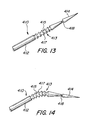
- Fig. 13 is a side elevational view of a portion of the present invention illustrating a bendable portion.
- Fig. 14 is a side elevational view illustrating bending of the embodiment illustrated in Fig. 13.
- Fig. 1 illustrates an embodiment of the present invention, a dental wedge with a frangible handle 10.
- a handle 12 is attached to a dental wedge 14.
- the dental wedge 14 may be of any desired shape suitable for wedging.
- a neck 16 having a reduced lateral dimension or diameter is placed between the dental wedge 14 and the handle portion 12.
- a frangible portion 18 has a further reduced diameter or lateral dimension.
- the dental wedge and handle 10 may be made of any suitable material, for example, plastic or wood.
- the dental wedge with handle 10 is made of a suitable plastic.
- the frangible portion 18 permits the dental wedge portion 14 and the handle portion 12 to be separated.
- the handle 12 is preferably substantially longer than the wedge 14.
- the handle 12 may be as much as four times longer than the length of the dental wedge 14. For example, if the dental wedge 14 is approximately 0.5 inches or 1.3 centimeters long or longer, the handle may be approximately 4 inches or 6.2 centimeters long or longer.
- the substantial length of the handle 12 permits easy grasping and
- Fig. 2 illustrates a portion of the present invention rotated slightly from that of Fig. 1 along the longitudinal axis. A flat face of the dental wedge portion 14 is more clearly illustrated in Fig. 2.
- Fig. 3 illustrates different points along the longitudinal length of the dental wedge portion 14. At a location 14A, the lateral dimension of the dental wedge 14 is greater than that at location 14B.
- Fig. 4 illustrates the cross-section taken along line 4-4 illustrated in Fig. 3 at location 14A.
- the cross-section is generally triangular and may be an equilateral triangle or an isosceles triangle. However, other shapes or triangular cross-sections may also be used.
- Fig. 5 illustrates the cross-section taken along line 5-5 at point 14B in Fig. 3.
- the cross-section at location 14B is also substantially a triangle. However, the lateral dimension at location 14B is less than that at location 14A illustrated in Fig. 3. Accordingly, when the apex or point of the dental wedge portion 14 is inserted between teeth, it acts as a wedge to separate or apply pressure to the teeth or other abutting surface.
- Fig. 6 illustrates the operation of the present invention and its application in a restorative dental procedure.
- Two teeth 20 and 21 adjacent to each other form a gap between which the dental wedge portion 14 is inserted.
- Tooth 21, having a prepared cavity 24 therein and which is to be filled with a dental restorative material, has a matrix band 22 placed adjacent thereto.
- the matrix band 22 forms a wall so as to contain the dental restorative material.
- the matrix band may generally encircle the whole tooth 21, but for illustrative purposes only a portion thereof is shown.
- the dental wedge portion 14 is inserted with handle portion 12 in the direction of arrow 26 between the two teeth 20 and 21.
- the handle 12 may remain in place or, if desired to provide additional working area, be removed by either rocking or moving the handle portion 12 back and forth in the direction of arrow 28.
- the handle portion 12 may also be rotated in the direction of arrow 30. Either method of rocking, rotating, spinning, twisting or combination will result in the frangible portion 18 breaking. This results in the handle portion 12 and the wedge portion 14 to become separate.
- Fig. 7 illustrates the dental wedge portion 14 remaining between the teeth 20 and 21 after the handle portion has been separated from the dental wedge portion 14.
- Prepared cavity 24 may then be filled with a dental restorative. With the handle portion removed, additional working area is obtained.
- Fig. 8 is a side elevational view illustrating the positioning of the dental wedge portion 14 at the base of the tooth 21. This holds the matrix band 22 in tight conformance to the base of the tooth 21, permitting a dental restorative to be filled within the prepared cavity 24.
- Fig. 9 illustrates another embodiment of the present invention.
- the dental wedge and handle 110 has a handle portion 112 and a dental wedge portion 114. Separating the dental wedge portion 114 and the handle portion 112 is a neck portion 116. A frangible portion 118 is formed within the neck portion 116. The frangible portion 118 may have a reduced lateral dimension than that of neck portion 116. Alternatively, neck portion 116 may be sufficiently frangible so that any further reduced frangible portion 118 may not be needed.
- the dental wedge portion 114 has a curved front 114A and a rectilinear rear portion 114B. The face 114C or angled sides function as the wedge. This shape provides a more anatomical wedge.
- Fig. 10 is a front elevational view illustrating the dental wedge 114.
- the curved front 114A and the rectilinear rear portion 114B are more clearly illustrated.
- Fig. 11 illustrates another embodiment of the present invention of a dental wedge and handle 210.
- handle portion 212 is attached to the dental wedge portion 214 by a frangible portion 218.
- a neck portion 216 provides a transition between the dental wedge portion 214 and the frangible portion 218.
- the dental wedge portion 214 may have a triangular cross-section having three sides or faces. Each side or face may have a textured surface 214A so as to facilitate gripping between the teeth or matrix band.
- the textured surface 214A may be a roughened surface, dimples, or other gripping surface.
- Fig. 12 illustrates another embodiment of the present invention, a dental wedge and frangible handle 310.
- a handle portion 312 is placed adjacent the dental wedge portion 314 and is separated by a frangible portion 318.
- the dental wedge portion 314 may have a generally triangular cross-section having three sides or faces with ribs 314A placed laterally across each of the sides or faces.
- the ribs 314A may be raised or recessed portions placed on the face of the dental wedge portion 314.
- Figs. 13 and 14 illustrates yet another embodiment of the present invention of a dental wedge and frangible handle 410.
- a means for bending or a bendable portion 413 is utilized.
- the dental wedge with a frangible handle 410 has a handle portion 412 and a dental wedge portion 414. Adjacent the dental wedge portion 414 is a frangible portion 418. Adjacent the frangible portion 418 is a bendable portion 413.
- the bendable portion 413 may take a variety of forms as long as it results in a bendable portion. However, in this embodiment, the bendable portion comprises a plurality of valleys 415 and peaks 417. Therefore, alternating reduced lateral dimensions and increased lateral dimensions exist along the bendable portion 413.
- the dental wedge and frangible handle 410 can be bent along the bendable portion 413 so as to facilitate placement of a dental wedge portion 414.
- the bendable portion may take other forms, for example a crimp.
- the bendable portion 413 may also take other equivalent forms.
- Fig. 14 illustrates the dental wedge and frangible handle 410 being bent along the bendable portion 413.
- the bendable portion 413 greatly facilitates the positioning of the dental wedge portion 414 between teeth in hard to reach areas such as in the back of the mouth.
- the present invention has many advantages over the dental wedges of the prior art.
- the possibility of losing a relatively small wedge in a patient's mouth prior to placement is reduced. Additionally, secure placement of the wedge can be assured prior to removal of the handle.
- the handle should the handle be desired to be retained, it will also facilitate removal or readjustment of the dental wedge.
- a dentist or dental technician can easily position the wedge with must less dexterity than required in conventional dental wedge placement using forceps, tweezers, or pliers. Additionally, the need for sterilizing instruments use to place prior wedges is eliminated. As a result, the possibility of cross-contamination is eliminated or substantially reduced.
- the bendable portion of the handle in one embodiment allows the operator to bend the dental wedge and frangible handle as necessary for convenient placement of the wedge portion.
- the present invention therefore greatly facilitates the placement of dental wedges in various dental procedures.
Landscapes
- Health & Medical Sciences (AREA)
- Oral & Maxillofacial Surgery (AREA)
- Dentistry (AREA)
- Epidemiology (AREA)
- Life Sciences & Earth Sciences (AREA)
- Animal Behavior & Ethology (AREA)
- General Health & Medical Sciences (AREA)
- Public Health (AREA)
- Veterinary Medicine (AREA)
- Dental Tools And Instruments Or Auxiliary Dental Instruments (AREA)
- Dental Prosthetics (AREA)
Applications Claiming Priority (2)
| Application Number | Priority Date | Filing Date | Title |
|---|---|---|---|
| US747596 | 2000-12-22 | ||
| US09/747,596 US6482007B2 (en) | 2000-12-22 | 2000-12-22 | Dental wedge with handle |
Publications (3)
| Publication Number | Publication Date |
|---|---|
| EP1219264A2 true EP1219264A2 (fr) | 2002-07-03 |
| EP1219264A3 EP1219264A3 (fr) | 2003-04-09 |
| EP1219264B1 EP1219264B1 (fr) | 2009-05-13 |
Family
ID=25005783
Family Applications (1)
| Application Number | Title | Priority Date | Filing Date |
|---|---|---|---|
| EP01130710A Expired - Lifetime EP1219264B1 (fr) | 2000-12-22 | 2001-12-21 | Coin interdentaire avec poignée |
Country Status (4)
| Country | Link |
|---|---|
| US (1) | US6482007B2 (fr) |
| EP (1) | EP1219264B1 (fr) |
| JP (1) | JP4563630B2 (fr) |
| DE (1) | DE60138681D1 (fr) |
Cited By (1)
| Publication number | Priority date | Publication date | Assignee | Title |
|---|---|---|---|---|
| US12324719B2 (en) | 2019-05-17 | 2025-06-10 | Magic-Trix Limited | Dental apparatus |
Families Citing this family (24)
| Publication number | Priority date | Publication date | Assignee | Title |
|---|---|---|---|---|
| US7223101B2 (en) * | 2002-06-28 | 2007-05-29 | Tom Garrison | Wedge for use in dental restoration |
| EP1518510A1 (fr) * | 2003-06-05 | 2005-03-30 | Corporacion O.I.B., S.L. | Element pour aider au placement de produits d'obturation dentaire |
| TWM266444U (en) * | 2003-08-29 | 2005-06-01 | Mesure Technology Co Ltd | Foldable sensing head and its clinical thermometer |
| US7303332B2 (en) * | 2003-08-29 | 2007-12-04 | Mesure Technology Co., Ltd. | Deflectable probe and thermometer |
| US9232988B2 (en) * | 2005-07-20 | 2016-01-12 | Rohit C L Sachdeva | Orthodontic device |
| US8206151B2 (en) | 2006-02-07 | 2012-06-26 | Triodent Holdings Limited | Dental wedge |
| US20080064003A1 (en) * | 2006-09-13 | 2008-03-13 | Clark David J | Dental Matrix Devices And A Seamless, Single Load Cavity Preparation And Filling Technique |
| US8641419B2 (en) * | 2007-07-25 | 2014-02-04 | David J. Clark | Methods and devices for fixed dental restoration |
| US8393897B2 (en) * | 2007-11-07 | 2013-03-12 | David J. Clark | Methods and devices for diastema closure |
| EP2072022A1 (fr) | 2007-12-18 | 2009-06-24 | Ernst Mühlbauer GmbH & Co.KG | Dispositif de suppression de résidus liquides et/ou de gel sur des surfaces dentaires |
| EP2072021A1 (fr) * | 2007-12-18 | 2009-06-24 | Ernst Mühlbauer GmbH & Co.KG | Dispositif d'infiltration de lésions de l'émail dans la zone interdentaire |
| US20090191506A1 (en) | 2008-01-29 | 2009-07-30 | Clark David J | Dental Composite Dispenser For Injection Molded Filling Techniques |
| US20110171596A1 (en) | 2010-01-14 | 2011-07-14 | Clark David J | Dental Wedge |
| US20120045734A1 (en) * | 2010-08-23 | 2012-02-23 | Thai Hung M | Dental Wedge Device With Guiding Wire |
| DE102010040414A1 (de) * | 2010-09-08 | 2011-01-13 | Voco Gmbh | Interdentalkeil |
| US9456880B1 (en) * | 2011-10-14 | 2016-10-04 | George A Sanchez | Dental wedge with a flexible tubing suction line |
| US9358080B2 (en) | 2012-03-26 | 2016-06-07 | David J. Clark | Dental separator ring |
| JP6085098B2 (ja) * | 2012-05-01 | 2017-02-22 | 紫朗 高梨 | アプリケーター |
| CN104968295A (zh) * | 2012-05-31 | 2015-10-07 | 容迪厄姆控股有限公司 | 具有非对称侧的牙楔 |
| USD720455S1 (en) * | 2012-10-31 | 2014-12-30 | Colldent Y.A Ltd | Dental wedge |
| CA2951197C (fr) | 2014-06-04 | 2022-07-19 | David J. Clark | Cale dentaire |
| US10092372B1 (en) | 2018-04-03 | 2018-10-09 | King Saud University | Elastically tensioned dental matrix wedge |
| US20210137657A1 (en) * | 2019-11-12 | 2021-05-13 | Sylvia McPartland | Interdental Cleaning Device |
| EP4059463A1 (fr) * | 2021-03-16 | 2022-09-21 | medmix Switzerland AG | Applicateur et procédé de formation d'un applicateur |
Family Cites Families (13)
| Publication number | Priority date | Publication date | Assignee | Title |
|---|---|---|---|---|
| US3193094A (en) * | 1961-03-20 | 1965-07-06 | Robert J Schulstad | Dental wedges and package thereof |
| US3636631A (en) * | 1970-12-18 | 1972-01-25 | Benjamin F Tofflemire | Teeth-separating wedges for use during filling operations |
| US3783883A (en) * | 1972-05-16 | 1974-01-08 | D Alexander | Combination dental floss holder and toothpick |
| JPS52148986A (en) * | 1976-04-07 | 1977-12-10 | Biggs Anthony J | Surgical throwaway hand wrench |
| US4337041A (en) * | 1980-09-29 | 1982-06-29 | Harsany John D | Dental wedge |
| US4696646A (en) * | 1985-12-23 | 1987-09-29 | Maitland Ronald I | Dental wedge and method of using same |
| US4715816A (en) * | 1986-08-25 | 1987-12-29 | Andrew Mogelof | Adjustable dental wedging system |
| US4747777A (en) * | 1987-04-23 | 1988-05-31 | Ward Ridley C | Dental instrument |
| US4805646A (en) * | 1987-07-24 | 1989-02-21 | Marat Shimenkov | Toothpick |
| JPH0328879U (fr) * | 1989-07-31 | 1991-03-22 | ||
| EP1014882B1 (fr) | 1997-08-27 | 2008-10-29 | John E. Garrison | Coin dentaire ameliore destine a etre utilise dans la restauration dentaire |
| US6135771A (en) * | 1997-12-02 | 2000-10-24 | Centrix, Inc. | Dental cartridge having an attachable delivery portion |
| US5890901A (en) | 1998-04-22 | 1999-04-06 | Ultradent Products, Inc. | Dental wedge with neck |
-
2000
- 2000-12-22 US US09/747,596 patent/US6482007B2/en not_active Expired - Lifetime
-
2001
- 2001-12-20 JP JP2001387419A patent/JP4563630B2/ja not_active Expired - Lifetime
- 2001-12-21 EP EP01130710A patent/EP1219264B1/fr not_active Expired - Lifetime
- 2001-12-21 DE DE60138681T patent/DE60138681D1/de not_active Expired - Lifetime
Non-Patent Citations (1)
| Title |
|---|
| None |
Cited By (1)
| Publication number | Priority date | Publication date | Assignee | Title |
|---|---|---|---|---|
| US12324719B2 (en) | 2019-05-17 | 2025-06-10 | Magic-Trix Limited | Dental apparatus |
Also Published As
| Publication number | Publication date |
|---|---|
| EP1219264A3 (fr) | 2003-04-09 |
| US20020081552A1 (en) | 2002-06-27 |
| DE60138681D1 (de) | 2009-06-25 |
| EP1219264B1 (fr) | 2009-05-13 |
| JP4563630B2 (ja) | 2010-10-13 |
| US6482007B2 (en) | 2002-11-19 |
| JP2002200097A (ja) | 2002-07-16 |
Similar Documents
| Publication | Publication Date | Title |
|---|---|---|
| US6482007B2 (en) | Dental wedge with handle | |
| US5425635A (en) | Matrix band segment and restoration procedure | |
| Ruddle | Nonsurgical retreatment | |
| US7976308B2 (en) | Dental wedges and methods | |
| KR101501954B1 (ko) | 치주 수술용 견인기 | |
| US10299890B2 (en) | Dental wedge | |
| US20160074135A1 (en) | Adjustable dental hand instrument | |
| US3510948A (en) | Dental wedge | |
| US20190231476A1 (en) | Dental separator and matrix system for producing dental restorations | |
| US20110262878A1 (en) | Dental matrix | |
| Keogh et al. | Creating tight, anatomically correct interproximal contacts | |
| US6705865B1 (en) | Dental hand instrument | |
| US20070087310A1 (en) | Dental matrices and clamps therefor | |
| CN1396815A (zh) | 用于取出牙齿器件的器械 | |
| US5030092A (en) | Method and apparatus for temporary attachment of a safety line to dental restorations and appliances | |
| US5836767A (en) | Dental shim | |
| Sieraski et al. | Silver point retreatment: review and case report | |
| JP3594867B2 (ja) | 破折片除去用歯科器具 | |
| US12004918B2 (en) | Dental restoration system | |
| US6974320B2 (en) | Tools and methods for measuring tooth reduction | |
| Williamson et al. | Removing a cemented fixed prosthesis using a crown remover | |
| WO2006022663A1 (fr) | Outils et procédés de mesure d’une réduction dentaire |
Legal Events
| Date | Code | Title | Description |
|---|---|---|---|
| PUAI | Public reference made under article 153(3) epc to a published international application that has entered the european phase |
Free format text: ORIGINAL CODE: 0009012 |
|
| AK | Designated contracting states |
Kind code of ref document: A2 Designated state(s): AT BE CH CY DE DK ES FI FR GB GR IE IT LI LU MC NL PT SE TR |
|
| AX | Request for extension of the european patent |
Free format text: AL;LT;LV;MK;RO;SI |
|
| PUAL | Search report despatched |
Free format text: ORIGINAL CODE: 0009013 |
|
| AK | Designated contracting states |
Kind code of ref document: A3 Designated state(s): AT BE CH CY DE DK ES FI FR GB GR IE IT LI LU MC NL PT SE TR Designated state(s): AT BE CH CY DE DK ES FI FR GB GR IE IT LI LU MC NL PT SE TR |
|
| AX | Request for extension of the european patent |
Extension state: AL LT LV MK RO SI |
|
| 17P | Request for examination filed |
Effective date: 20031008 |
|
| AKX | Designation fees paid |
Designated state(s): DE GB IT SE |
|
| 17Q | First examination report despatched |
Effective date: 20040401 |
|
| GRAP | Despatch of communication of intention to grant a patent |
Free format text: ORIGINAL CODE: EPIDOSNIGR1 |
|
| GRAS | Grant fee paid |
Free format text: ORIGINAL CODE: EPIDOSNIGR3 |
|
| GRAA | (expected) grant |
Free format text: ORIGINAL CODE: 0009210 |
|
| AK | Designated contracting states |
Kind code of ref document: B1 Designated state(s): DE GB IT SE |
|
| REG | Reference to a national code |
Ref country code: GB Ref legal event code: FG4D |
|
| REF | Corresponds to: |
Ref document number: 60138681 Country of ref document: DE Date of ref document: 20090625 Kind code of ref document: P |
|
| REG | Reference to a national code |
Ref country code: SE Ref legal event code: TRGR |
|
| PLBE | No opposition filed within time limit |
Free format text: ORIGINAL CODE: 0009261 |
|
| STAA | Information on the status of an ep patent application or granted ep patent |
Free format text: STATUS: NO OPPOSITION FILED WITHIN TIME LIMIT |
|
| 26N | No opposition filed |
Effective date: 20100216 |
|
| REG | Reference to a national code |
Ref country code: DE Ref legal event code: R079 Ref document number: 60138681 Country of ref document: DE Free format text: PREVIOUS MAIN CLASS: A61C0005120000 Ipc: A61C0005800000 |
|
| PGFP | Annual fee paid to national office [announced via postgrant information from national office to epo] |
Ref country code: SE Payment date: 20191220 Year of fee payment: 19 |
|
| PGFP | Annual fee paid to national office [announced via postgrant information from national office to epo] |
Ref country code: IT Payment date: 20191231 Year of fee payment: 19 |
|
| PGFP | Annual fee paid to national office [announced via postgrant information from national office to epo] |
Ref country code: GB Payment date: 20191220 Year of fee payment: 19 |
|
| PGFP | Annual fee paid to national office [announced via postgrant information from national office to epo] |
Ref country code: DE Payment date: 20201229 Year of fee payment: 20 |
|
| REG | Reference to a national code |
Ref country code: SE Ref legal event code: EUG |
|
| GBPC | Gb: european patent ceased through non-payment of renewal fee |
Effective date: 20201221 |
|
| PG25 | Lapsed in a contracting state [announced via postgrant information from national office to epo] |
Ref country code: IT Free format text: LAPSE BECAUSE OF NON-PAYMENT OF DUE FEES Effective date: 20201221 |
|
| PG25 | Lapsed in a contracting state [announced via postgrant information from national office to epo] |
Ref country code: SE Free format text: LAPSE BECAUSE OF NON-PAYMENT OF DUE FEES Effective date: 20201222 Ref country code: GB Free format text: LAPSE BECAUSE OF NON-PAYMENT OF DUE FEES Effective date: 20201221 |
|
| REG | Reference to a national code |
Ref country code: DE Ref legal event code: R071 Ref document number: 60138681 Country of ref document: DE |