EP1219325A2 - Übungsgerät zum Armdrücken - Google Patents
Übungsgerät zum Armdrücken Download PDFInfo
- Publication number
- EP1219325A2 EP1219325A2 EP01130535A EP01130535A EP1219325A2 EP 1219325 A2 EP1219325 A2 EP 1219325A2 EP 01130535 A EP01130535 A EP 01130535A EP 01130535 A EP01130535 A EP 01130535A EP 1219325 A2 EP1219325 A2 EP 1219325A2
- Authority
- EP
- European Patent Office
- Prior art keywords
- head unit
- pusher arm
- main base
- spring
- articulated
- Prior art date
- Legal status (The legal status is an assumption and is not a legal conclusion. Google has not performed a legal analysis and makes no representation as to the accuracy of the status listed.)
- Withdrawn
Links
- 230000000694 effects Effects 0.000 description 2
- 230000000717 retained effect Effects 0.000 description 2
- 238000007792 addition Methods 0.000 description 1
- 230000006835 compression Effects 0.000 description 1
- 238000007906 compression Methods 0.000 description 1
- 230000000994 depressogenic effect Effects 0.000 description 1
- 239000002184 metal Substances 0.000 description 1
- 230000001953 sensory effect Effects 0.000 description 1
- 238000004088 simulation Methods 0.000 description 1
- 238000003466 welding Methods 0.000 description 1
Images





Classifications
-
- A—HUMAN NECESSITIES
- A63—SPORTS; GAMES; AMUSEMENTS
- A63B—APPARATUS FOR PHYSICAL TRAINING, GYMNASTICS, SWIMMING, CLIMBING, OR FENCING; BALL GAMES; TRAINING EQUIPMENT
- A63B21/00—Exercising apparatus for developing or strengthening the muscles or joints of the body by working against a counterforce, with or without measuring devices
- A63B21/00058—Mechanical means for varying the resistance
- A63B21/00069—Setting or adjusting the resistance level; Compensating for a preload prior to use, e.g. changing length of resistance or adjusting a valve
- A63B21/00072—Setting or adjusting the resistance level; Compensating for a preload prior to use, e.g. changing length of resistance or adjusting a valve by changing the length of a lever
-
- A—HUMAN NECESSITIES
- A63—SPORTS; GAMES; AMUSEMENTS
- A63B—APPARATUS FOR PHYSICAL TRAINING, GYMNASTICS, SWIMMING, CLIMBING, OR FENCING; BALL GAMES; TRAINING EQUIPMENT
- A63B21/00—Exercising apparatus for developing or strengthening the muscles or joints of the body by working against a counterforce, with or without measuring devices
- A63B21/40—Interfaces with the user related to strength training; Details thereof
- A63B21/4041—Interfaces with the user related to strength training; Details thereof characterised by the movements of the interface
- A63B21/4047—Pivoting movement
-
- A—HUMAN NECESSITIES
- A63—SPORTS; GAMES; AMUSEMENTS
- A63B—APPARATUS FOR PHYSICAL TRAINING, GYMNASTICS, SWIMMING, CLIMBING, OR FENCING; BALL GAMES; TRAINING EQUIPMENT
- A63B23/00—Exercising apparatus specially adapted for particular parts of the body
- A63B23/035—Exercising apparatus specially adapted for particular parts of the body for limbs, i.e. upper or lower limbs, e.g. simultaneously
- A63B23/12—Exercising apparatus specially adapted for particular parts of the body for limbs, i.e. upper or lower limbs, e.g. simultaneously for upper limbs or related muscles, e.g. chest, upper back or shoulder muscles
- A63B23/129—Exercising apparatus specially adapted for particular parts of the body for limbs, i.e. upper or lower limbs, e.g. simultaneously for upper limbs or related muscles, e.g. chest, upper back or shoulder muscles for arm wrestling
-
- A—HUMAN NECESSITIES
- A63—SPORTS; GAMES; AMUSEMENTS
- A63B—APPARATUS FOR PHYSICAL TRAINING, GYMNASTICS, SWIMMING, CLIMBING, OR FENCING; BALL GAMES; TRAINING EQUIPMENT
- A63B2208/00—Characteristics or parameters related to the user or player
- A63B2208/12—Characteristics or parameters related to the user or player specially adapted for children
Definitions
- the present invention relates to a training device for hand-wrestling.
- Hand-wrestling once mainly practiced in pubs and similar establishments, is becoming increasingly popular and, indeed, professional, with regional and even national competitions being held everywhere.
- a hand-wrestling training device comprising an elongated main base carrying at one of its ends a mounting means to which one end of a spring means is hingedly articulated; at least one mounting plate fixedly attached to said main base near the other end of said base; a head unit pivotably mounted in said mounting plate; a pusher arm fixedly attached at one of its ends to said head unit and provided with a plate element at the other one of its ends; a body movable in translation along said pusher arm, the second end of said spring means being articulated to said body; adjustment means for altering the mechanical advantage afforded to the user by moving said body along said pusher arm, thereby altering the effective length of said pusher arm, and a gripping handle hingedly attached to a portion of said head unit; said gripping handle, when turned downward, causing said pusher arm to be applied against the opposing force of said spring.
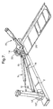
- a device having an elongated main base 2, advantageously made of a rectangular metal profile.
- base 2 Fixedly attached to the left end of base 2, preferably by welding, is a clevis-like mount 4, to which, by means of pin 6, is hingedly articulated the lug-shaped end 8 of a commercially available, so-called gas spring 9, which consists of a cylinder 10 and a plunger 12 and contains a pre-compressed gas.
- gas spring 9 which consists of a cylinder 10 and a plunger 12 and contains a pre-compressed gas.
- Two parallel mounting plates 14 are fixedly attached to base 2 close to its other end, at a distance from one another and substantially perpendicular to the base, and extending through a window 3 down to the bottom of the base. Plates 14 are provided with co-axial bores 16. Shaft 18, fixedly connected to a head unit 20 by means of pin 21, is pivotably mounted in bores 16. Shaft 18 projects on both sides beyond mounting plates 14, each projecting portion being provided with a slot 22. A bar 24, constituting the lower portion of a handle 25, can be hingedly articulated into either of slots 22 with the use of a pin 26.
- Fig. 1 the device is shown rigged for a right-handed user.
- Secondary base 28 is constrained in its perpendicular direction relative to base 2 by a ridge-like rib 30 that fits into a corresponding cut across base 2 and is locked into the selected position by means of thumbscrew 32 (Fig. 2).
- thumbscrew 32 is unscrewed, base 28 is slid over to the other side, and thumbscrew 32 is screwed into another threaded hole 34.
- the elbow-supporting pad 36 rests freely on base 28, and is transferred to the other side when base 28 is slid over. Obviously, handle 25 is also transferred to the other side.
- Both bases 2 and 28 rest on rubber pads 29 which, when the user presses his elbow against supporting pad 36, prevent the right end of base 2 from being raised during the initial application of force to handle 25 and produce a sufficient amount of friction to obviate any need to clamp the device to the table.
- the upper half of tube 37 is covered by a rubber sleeve 42, which serves as the gripping position of handle 25. Due to the above-described articulation of bar 24 to shaft 18, handle 25 can move relative to head unit 20 with one degree of freedom in rotation, in a plane containing the axis of pivoting of head unit 20, i.e., of shaft 18.
- Pusher arm 44 fixedly attached to, and thus rotating together with, head unit 20.
- Pusher arm 44 is in the form of a channel profile provided with an end plate 46 (Fig. 3).
- the threaded shaft 48 of a thumbscrew 50 passes through end plate 46 (seen to better effect in Fig. 5), constrained to one degree of freedom in rotation by a retaining ring 52 (Fig. 3).
- a body or block 54 (shown at an enlarged scale in Fig. 4), provided with an internal thread 56 which engages shaft 48 of thumbscrew 50. Consequently, when thumbscrew 50 is rotated, block 54, constrained by the channel shape of arm 44 to one degree of freedom in translation, will move either up or down arm 44, depending on the sense of rotation.
- slot 58 in which is seated the lug-shaped end 60 of plunger 12, hingedly articulated to block 54 by means of a pin 62.
- an engraved line 64 constituting the index line for a scale 66 provided on at least one of the wings of the channel profile of arm 44.
- Scale 66 is arbitrary, serving mainly as a reference for the user.
- a hole 68 in pusher arm 44 serves for assembly purposes only: it is through this hole that pin 62 is introduced into block 54, to serve as a hinge pin for the lug-shaped end 60 of plunger 12.
- An essential component of the device is a mechanical stop that defines the starting position of gripping handle 25, in which the handle must be located in a vertical plane.
- This stop is in the shape of a blade 70 (seen in Figs. 2, 5 and 6) rigidly attached to mounting plates 14.
- the slanting edge 72 of blade 70 is a safety feature, protecting anyone's fingers near blade 70, should the user suddenly let go of the depressed handle 25, causing pushing arm 44 to be flung back.
- Figs. 5 and 6 illustrate the two limit positions of block 54.
- the user With the block in the position shown in Fig. 5, the user has the smallest mechanical advantage and, consequently, has to apply the greatest force to overcome the counter-force of spring 9.
- the block in the position shown in Fig. 6 the user has the largest mechanical advantage and, consequently, can overcome spring 9 by application of a relatively small force.
- a second embodiment of the invention comes even closer to a full simulation of the real event, inasmuch as the device is able, in principle, to "beat" the user by forcing his hand down towards the table.
- the components of the first and second embodiments are substantially identical, with some exceptions and additions. Seen in Fig. 7 is a similar base 2, to which are attached two pairs of mounting plates 14, 14', extending through window 3 in base 2, each pair having its own head unit 20, 20', respectively.
- Pusher arm 44 is fixedly attached to head unit 20', with plunger 12 of spring 9 being articulated to block 54 which, as in the first embodiment, is slidingly mounted inside arm 44 (Fig. 8).
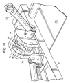
- Head unit 20 serves as a cable drum around which is slung a doubled-up cable 74, as seen to best effect in Fig. 10.
- Cable 74 is partly led inside a groove 76 and, at its midpoint, is retained by a headed pin 78 (Figs. 10 and 11).
- the two ends of cable 74 are provided with terminals 80, which are fixedly attached to tabs 82 that are either integral parts of pusher arm 44, or fixedly connected to it.
- Head unit 20 fulfills two functions: it serves as a cable drum, as already mentioned, and it defines the starting position, in which handle 25 is located in a vertical plane. This is effected by a pawl 84, pivotably mounted in a recess 85 in head unit 20 (Fig. 11). After handle 25 is moved from the position shown in Fig. 9 to a position slightly beyond the vertical position, the pawl is pushed down by the user's finger against the restoring force of a spring 86, as shown in Fig. 11. When the user's pressure on handle 25 is now reduced, with the user's finger still in position, pawl 84 will come to abut against a bridge element 88, thus serving as a positive stop.
- pawl 84 stays in position even after the user's finger is withdrawn (Fig. 12) and the "contest" can now begin. However, as soon as the user has tilted handle 25 to the slightest degree in the counter-clockwise direction, pawl 84 snaps back into recess 85 and ceases to function as a stop, thereby giving the device a chance to "defeat” the user, as spring 9 will now be able to rotate head unit 20 in the clockwise direction (Fig. 13), no longer being stopped by pawl 84, and thus urging the user's arm down towards the table.
- the mechanical advantage offered by the device is set by means of thumbscrew 50.
- Blade 70 (Fig. 9) now serves to define the horizontal position of handle 25.
- Fig. 7 can also be used for a fair competition between unequal partners, e.g., an adult and a child, with the adult operating handle 25 against the opposing force of spring 9.
- the junior partner sits on the opposite side of the table and grips a second handle 25 optionally provided and attached to the free end of shaft 18 (Fig. 1). With such an arrangement, the adult has to battle against the force of the junior plus the force of spring 9.
Landscapes
- Health & Medical Sciences (AREA)
- Orthopedic Medicine & Surgery (AREA)
- General Health & Medical Sciences (AREA)
- Physical Education & Sports Medicine (AREA)
- Life Sciences & Earth Sciences (AREA)
- Biophysics (AREA)
- Toys (AREA)
- Rehabilitation Tools (AREA)
Applications Claiming Priority (2)
| Application Number | Priority Date | Filing Date | Title |
|---|---|---|---|
| IL14061200A IL140612A0 (en) | 2000-12-28 | 2000-12-28 | Training device for hand-wrestling |
| IL14061200 | 2000-12-28 |
Publications (2)
| Publication Number | Publication Date |
|---|---|
| EP1219325A2 true EP1219325A2 (de) | 2002-07-03 |
| EP1219325A3 EP1219325A3 (de) | 2004-01-02 |
Family
ID=11074983
Family Applications (1)
| Application Number | Title | Priority Date | Filing Date |
|---|---|---|---|
| EP01130535A Withdrawn EP1219325A3 (de) | 2000-12-28 | 2001-12-21 | Übungsgerät zum Armdrücken |
Country Status (3)
| Country | Link |
|---|---|
| US (1) | US6652428B2 (de) |
| EP (1) | EP1219325A3 (de) |
| IL (1) | IL140612A0 (de) |
Families Citing this family (5)
| Publication number | Priority date | Publication date | Assignee | Title |
|---|---|---|---|---|
| KR101230536B1 (ko) * | 2006-02-13 | 2013-02-06 | 한로봇 주식회사 | 팔씨름 로봇 및 그 제어방법 |
| US8545373B2 (en) * | 2007-07-12 | 2013-10-01 | Peter Scott Borden | Shoulder stretcher and method of use |
| WO2010027859A2 (en) * | 2008-08-26 | 2010-03-11 | Jamos Llc | Portable mountable upper-body exercise device |
| US9314657B2 (en) * | 2014-06-02 | 2016-04-19 | Antonio L. Martinez | Exercise assembly |
| CN104436551A (zh) * | 2014-12-16 | 2015-03-25 | 周棹帆 | 一种掰手腕练习器 |
Family Cites Families (8)
| Publication number | Priority date | Publication date | Assignee | Title |
|---|---|---|---|---|
| US911925A (en) * | 1908-05-13 | 1909-02-09 | Victor M Del Valle Y Zeno | Wrist-developer and strength-tester. |
| US4129297A (en) * | 1976-06-14 | 1978-12-12 | Dolan John W | Arm wrestling device |
| DE2839300C2 (de) * | 1978-09-09 | 1982-04-22 | Wiba AG, Kriens | Krafttrainingsgerät |
| US4482149A (en) * | 1981-07-17 | 1984-11-13 | Weldon David E | Arm exercising device |
| US4603857A (en) * | 1984-02-10 | 1986-08-05 | Chipman Max C | Spring exercise device |
| US4564191A (en) * | 1984-06-04 | 1986-01-14 | Atkin Norman M | Arm wrestling machine |
| FR2630636A1 (fr) * | 1988-04-27 | 1989-11-03 | Argaud Henri Pierre | Dispositif pour la musculation et la readaptation des muscles a l'aide d'un dynamometre a ressort muni d'un lecteur |
| US5087038A (en) * | 1991-03-07 | 1992-02-11 | Hao Kuo Hua | Exercising apparatus for arms |
-
2000
- 2000-12-28 IL IL14061200A patent/IL140612A0/xx unknown
-
2001
- 2001-12-21 EP EP01130535A patent/EP1219325A3/de not_active Withdrawn
- 2001-12-27 US US10/032,768 patent/US6652428B2/en not_active Expired - Fee Related
Also Published As
| Publication number | Publication date |
|---|---|
| EP1219325A3 (de) | 2004-01-02 |
| US6652428B2 (en) | 2003-11-25 |
| US20020107120A1 (en) | 2002-08-08 |
| IL140612A0 (en) | 2002-02-10 |
Similar Documents
| Publication | Publication Date | Title |
|---|---|---|
| US4836531A (en) | Hand and wrist exercising means | |
| US5669862A (en) | Portable exercise device | |
| US4707884A (en) | Foldable handle for a skateboard | |
| US4157179A (en) | Arm exercising device | |
| US4231569A (en) | Exercising device | |
| US4858912A (en) | Arm exercising apparatus | |
| US6881177B2 (en) | Handgrip | |
| US4104743A (en) | Device for safety-helmet with ear mufflers | |
| US4861022A (en) | Portable forearm exerciser | |
| WO2006062746A3 (en) | Facial and neck muscle exercising device | |
| US6436017B1 (en) | Multi-function personal exerciser | |
| EP0350956A3 (de) | Tragbares Knie-Übungsgerät mit Handbetrieb | |
| US5449333A (en) | Bar having O-rings to secure the weight | |
| US5087031A (en) | Arm exerciser | |
| US4756522A (en) | Compact adjustable chest exercise device | |
| US6652428B2 (en) | Training device for hand-wrestling | |
| US4811944A (en) | Arm exerciser | |
| US5411453A (en) | Pull up device with thumb grasping knobs | |
| US5336140A (en) | Hand grip exerciser | |
| US4328733A (en) | Slide bar holder device for Hawaiian guitar | |
| US4171801A (en) | Frictional arm exercise device | |
| US5087038A (en) | Exercising apparatus for arms | |
| JPH11514261A (ja) | 光学装置位置決めのための調節装置を備えたヘッドバンド | |
| US5458554A (en) | Apparatus enabling one person to do arm-wrestling exercise | |
| US4351523A (en) | Arm wrestling exerciser |
Legal Events
| Date | Code | Title | Description |
|---|---|---|---|
| PUAI | Public reference made under article 153(3) epc to a published international application that has entered the european phase |
Free format text: ORIGINAL CODE: 0009012 |
|
| AK | Designated contracting states |
Kind code of ref document: A2 Designated state(s): AT BE CH CY DE DK ES FI FR GB GR IE IT LI LU MC NL PT SE TR |
|
| AX | Request for extension of the european patent |
Free format text: AL;LT;LV;MK;RO;SI |
|
| PUAL | Search report despatched |
Free format text: ORIGINAL CODE: 0009013 |
|
| AK | Designated contracting states |
Kind code of ref document: A3 Designated state(s): AT BE CH CY DE DK ES FI FR GB GR IE IT LI LU MC NL PT SE TR |
|
| AX | Request for extension of the european patent |
Extension state: AL LT LV MK RO SI |
|
| RIC1 | Information provided on ipc code assigned before grant |
Ipc: 7A 63B 21/008 B Ipc: 7A 63B 23/12 A |
|
| 17P | Request for examination filed |
Effective date: 20040512 |
|
| AKX | Designation fees paid |
Designated state(s): AT BE CH CY DE DK ES FI FR GB GR IE IT LI LU MC NL PT SE TR |
|
| 17Q | First examination report despatched |
Effective date: 20050705 |
|
| STAA | Information on the status of an ep patent application or granted ep patent |
Free format text: STATUS: THE APPLICATION IS DEEMED TO BE WITHDRAWN |
|
| 18D | Application deemed to be withdrawn |
Effective date: 20050701 |