EP1219403A1 - Dispositif d'injection amélioré pour presses d'injection pour matières plastiques - Google Patents
Dispositif d'injection amélioré pour presses d'injection pour matières plastiques Download PDFInfo
- Publication number
- EP1219403A1 EP1219403A1 EP01128815A EP01128815A EP1219403A1 EP 1219403 A1 EP1219403 A1 EP 1219403A1 EP 01128815 A EP01128815 A EP 01128815A EP 01128815 A EP01128815 A EP 01128815A EP 1219403 A1 EP1219403 A1 EP 1219403A1
- Authority
- EP
- European Patent Office
- Prior art keywords
- screw
- movement
- coupling
- injection assembly
- travelling
- Prior art date
- Legal status (The legal status is an assumption and is not a legal conclusion. Google has not performed a legal analysis and makes no representation as to the accuracy of the status listed.)
- Granted
Links
Images


Classifications
-
- B—PERFORMING OPERATIONS; TRANSPORTING
- B29—WORKING OF PLASTICS; WORKING OF SUBSTANCES IN A PLASTIC STATE IN GENERAL
- B29C—SHAPING OR JOINING OF PLASTICS; SHAPING OF MATERIAL IN A PLASTIC STATE, NOT OTHERWISE PROVIDED FOR; AFTER-TREATMENT OF THE SHAPED PRODUCTS, e.g. REPAIRING
- B29C45/00—Injection moulding, i.e. forcing the required volume of moulding material through a nozzle into a closed mould; Apparatus therefor
- B29C45/17—Component parts, details or accessories; Auxiliary operations
- B29C45/46—Means for plasticising or homogenising the moulding material or forcing it into the mould
- B29C45/47—Means for plasticising or homogenising the moulding material or forcing it into the mould using screws
- B29C45/50—Axially movable screw
- B29C45/5008—Drive means therefor
-
- B—PERFORMING OPERATIONS; TRANSPORTING
- B29—WORKING OF PLASTICS; WORKING OF SUBSTANCES IN A PLASTIC STATE IN GENERAL
- B29C—SHAPING OR JOINING OF PLASTICS; SHAPING OF MATERIAL IN A PLASTIC STATE, NOT OTHERWISE PROVIDED FOR; AFTER-TREATMENT OF THE SHAPED PRODUCTS, e.g. REPAIRING
- B29C45/00—Injection moulding, i.e. forcing the required volume of moulding material through a nozzle into a closed mould; Apparatus therefor
- B29C45/17—Component parts, details or accessories; Auxiliary operations
- B29C45/46—Means for plasticising or homogenising the moulding material or forcing it into the mould
- B29C45/47—Means for plasticising or homogenising the moulding material or forcing it into the mould using screws
- B29C45/50—Axially movable screw
- B29C45/5008—Drive means therefor
- B29C2045/5024—Drive means therefor screws rotated by the coaxial rotor of an electric motor
-
- B—PERFORMING OPERATIONS; TRANSPORTING
- B29—WORKING OF PLASTICS; WORKING OF SUBSTANCES IN A PLASTIC STATE IN GENERAL
- B29C—SHAPING OR JOINING OF PLASTICS; SHAPING OF MATERIAL IN A PLASTIC STATE, NOT OTHERWISE PROVIDED FOR; AFTER-TREATMENT OF THE SHAPED PRODUCTS, e.g. REPAIRING
- B29C45/00—Injection moulding, i.e. forcing the required volume of moulding material through a nozzle into a closed mould; Apparatus therefor
- B29C45/17—Component parts, details or accessories; Auxiliary operations
- B29C45/46—Means for plasticising or homogenising the moulding material or forcing it into the mould
- B29C45/47—Means for plasticising or homogenising the moulding material or forcing it into the mould using screws
- B29C45/50—Axially movable screw
- B29C45/5008—Drive means therefor
- B29C2045/5028—Drive means therefor screws axially driven by the coaxial rotor of an electric motor
Definitions
- This invention concerns an improved injection assembly for injection presses for plastic materials.
- presses and devices for injection moulding are used in which resins, composed of plastics, are heated to be brought to the molten state in a heating cylinder and are injected, at high pressure, into a cavity of a mould so as to fill the mould.
- the molten resin is cooled in the mould so that it hardens and forms the moulded product.
- the mould is opened and the moulded product is extracted, which may then be stored or proceed to further processing phases.
- the injection moulding device comprises a moulding assembly and an injection assembly.
- the moulding assembly generally comprises two half-moulds mounted respectively on a fixed plate and on a mobile plate, so that the mould may be opened and closed by moving the mobile plate backwards and forwards.
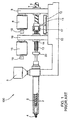
- Fig. 1 schematically shows a prior art injection assembly, indicated as a whole with the reference number 100.
- the injection assembly 100 comprises a heating cylinder 2 for bringing to a molten state the resins fed through a hopper 3, and an injection nozzle 4 for injecting the molten material into the cavity in the mould.
- Inside the heating cylinder 2 is a plasticating or plasticator screw 5 which must perform a rotary movement around its own axis to plasticate the resins and a forward travelling movement to inject the molten material and a retracting movement to admit of the resins from the hopper 3.
- the plasticating screw 5 is moved by means of a system of electric motors.
- a screw and nut screw system is provided, in which a screw 6 engages in a nut screw 7.
- the nut screw 7 is driven by a motor 8 by means of a reduction unit 9 fixed to a machine chassis or frame 10.
- the screw 6 is prevented from rotating around its own axis by means of an anti-rotation device.
- This anti-rotation device comprises a rod 11 fixed to the screw 6 and a stop block 12 fixed to the machine chassis 10. In this way the rod 11, abutting against the stopping block 12, prevents rotation of the screw 6, allowing only travelling movement. Accordingly, by turning the electric motor in one direction or in the opposite direction, forward or backward movement of the screw 6 is allowed which brings the plasticating screw 5 with it.
- the electric motors 8 and 15 are equipped respectively with encoder type sensors 18 and 19 to perform the speed adjustments required in the various phases of the work cycle.
- the injection assembly 100 has a drawback, due to the fact that each electric motor 8 or 15 is dedicated either to the travelling phase or to the rotating phase of the plasticating screw 5. Therefore the power to be installed for each motor is equal to the maximum power required for the phase with which it is associated. Consequently, during the travelling phase of the plasticating screw 5, there will be an overload of the motor 8, while the motor 15 remains inactive; on the other hand, during the rotating phase of the plasticating screw 5 there will be an overload of the motor 15, while the motor 8 remains inactive. This leads to an excessive waste of energy and rapid wear of the motors, which practically always work at maximum power.
- WO 97/18938 discloses a drive apparatus for an injection unit, in which the feed screw, in the plastication and injection phase, is driven by a ball screw and by a drive motor.
- three one-way clutches are provided: the first between the feed screw and the frame, the second between the drive motor and the feed screw, and the third between the drive motor and the ball screw.
- the aim of the invention is to eliminate these problems, providing an improved injection assembly for injection presses for plastic materials which has a simple construction and is practical, economic, versatile and simple to make.
- the electric injection assembly for injection presses for plastic materials has a plasticating or plasticator screw connected to a movement screw.
- the movement screw is preferably a ball screw and it is rotated by a main motor coupled to it and mounted on a support that slides horizontally on the machine chassis to perform the travelling movement of the movement screw.
- a nut screw, engaged with the movement screw, is fitted on the machine chassis with bearings and is rotated by an auxiliary motor.
- the nut screw can rotate only in the direction of rotation for the plasticating screw, in the opposite direction it is blocked by an anti-rotation system.
- the coupling between the movement screw and the plasicating screw is provided by a first coupling integral with the plasticating screw and a second coupling integral with movement screw.
- a thrust bearing and a free wheel or one-way clutch are interposed between the two couplings, the one-way clutch allowing the rotation only in the plastication direction.
- the pure travelling movement of the plasticating screw for the injection phase is obtained by blocking the nut screw and operating the main motor which, by rotating the movement screw, gives the forward movement.
- the direction of rotation of the main motor is inverted. Therefore the one-way clutch is engaged and it allows the movement screw to be integral in rotation with the plasticating screw.
- the nut screw is moved by the auxiliary electric motor by means of a reduction gear which only controls correct reverse movement of the plasticating screw.
- the injection assembly according to the invention provides an operating mechanism based principally on the use of only one electric power drive composed of the main motor coupled directly to the movement screw.
- the main motor is of a suitable size to be able to perform both the injection phase and the plasticating phase without a heavy reduction stage.
- the control of the productive process is also very simple because it relies only on the main motor for injection, while for plastication the back pressure is controlled on the auxiliary motor.
- connection between the movement screw and the plasticating screw is very simple and effective, since it does not provide any complex construction due to presence of more one-way clutches, as in the injection units according to the prior art.
- Fig. 2 schematically shows a first embodiment of an injection assembly according to the invention, indicated as a whole with the reference number 1. Elements which are the same as or corresponding to those already illustrated in Fig. 1 (concerning the prior art plasticating assembly 100) are indicated with the same reference numbers.
- a plasticating or plasticator screw 5 is connected by means of a first coupling 20 and a second coupling 40 to a movement screw 30.
- the first coupling 20 is integral with the plasticating screw 5 and the second coupling 40 is integral with the movement screw 30.
- a thrust bearing 50 and a free wheel 60 are fitted between the first coupling 20 and the second coupling 40.
- the free wheel 60 acts as an anti-rotation system, that is it allows a relative rotation of the second coupling 40 with respect to the first coupling 20 in one direction and not in the opposite direction.
- the movement screw 30 is connected by means of a second coupling 40 to a main electric motor 42.
- the second coupling 40 is integrally fixed to rotor 41 of the main electric motor 42.
- a stator 43 of the main electric motor is fixed to a casing 44 supported by a profiled guide 70 which slides on a track 71 integral with the machine chassis 10.
- Between the casing 44 and the first coupling 20 are fitted thrust bearings 81 and a free wheel 80 which acts as an anti-rotation system.
- a threaded part of the movement screw 30 engages in a respective nut screw 31 driven by an auxiliary electric motor 32 by means of a reduction unit 33.
- the nut screw 31 is supported, by means of bearings 37, by the machine chassis 10.
- a free wheel 34 is interposed which acts as an anti-rotation system.
- a head 35 of a tie rod 38 (in dash lines) is positioned which extends inside the movement screw 30 to connect to the first coupling 20 integral with the plasticating screw 5.
- a thrust bearing 36 is inserted which allows a relative rotation between the movement screw 30 and the assembly of the first coupling 20 and the tie rod 38.
- the plasticating screw 5 must be able to move forward to push the molten material towards the mould.
- the main motor 42 is operated, the rotor 41 of which turns in a clockwise direction (viewed from the right in the figure), causing rotation of the second coupling 40 which in turn rotates the movement screw 30 which is rigidly connected to it.
- the nut screw 31 will tend to turn in the same direction as the movement screw 30, since it is made to rotate by the movement screw 30. Consequently the nut screw turns the reduction unit 33 and the motor shaft 39 until the anti-rotation system 34, fitted on the motor shaft 39, is blocked.
- the movement screw 30 continues turning inside the nut screw 31 which remains still. Since the movement screw 30 has a righthand thread, it will move to the left (in the figure) pushing the first coupling 20 with the plasticating screw 5 through the bearing 50.
- the stator 43 of the main electric motor must always be able to interact with its rotor 41, so also the stator 43 must be integral in forward movement with the movement screw 39 during its travel.
- the stator 43 is set into the casing 44 resting on the guide 70 which allows movement along the track 71.
- the guide 70 also makes it possible to have reaction torque that prevents rotation of the casing 44.
- the anti-rotation system 60 is free to rotate and allows a relative rotating movement, through the thrust bearing 50, between the assembly formed by the rotor 41 and the movement screw 30 and the first coupling 20.
- the casing 44 could be caused to turn by the strong pressure that is created between the rotating elements and the races of the thrust bearing 50. To prevent all this from altering the progress of the injection phase, a system is provided which is able to provide a torque to contrast this tendency to rotate. The system acts directly on the coupling 20 through the anti-rotation device 80 which prevents rotation of the coupling 20 with respect to the casing 44.
- Control of the injection speed is obtained by regulating the rotation speed of the main motor 42, by means of a suitable drive mechanism, not shown.
- the plasticating screw 5 In the plastication phase the plasticating screw 5 must perform a rotary movement around its own axis. In this phase the plasticating screw 5 must be able to turn and travel at the same time, moving back gradually as the plastic material is accumulated at its front end. The plasticating screw 5 must guarantee a constant but adjustable pressure on the material, so as to be able to compact it.
- the rotor 41 of the main motor 42 turns in a counter-clockwise direction (viewed from the right in the figure), that is its direction of rotation is inverted with respect to the injection phase.
- the first coupling 20 and the second coupling 40 are kept integral thanks to the blocking of rotation by the free wheel 60. Consequently there is a single rotating body formed by the rotor 41, the couplings 20 and 40, the plasticating screw 5 and the movement screw 30. In this way the first coupling 20 transmits counter-clockwise rotation to the plasticating screw 5 and so the plastication phase begins.
- Control of the travel of the plasticating screw 5 is obtained by regulating the nut screw 31 with the auxiliary motor 32. In this way the nut screw 31 will turn at a substantially different speed from the movement screw 30, generating on it the necessary movements to enable it to rotate with suitable backward movements.
- a loop system is created, comparing the indicative pressure value of the plastic required by the process and the real value read by means of a pressure transducer placed on the injection chamber.
- This loop system is able to pilot the auxiliary motor 32 so that it maintains first a speed value of the nut screw 31 equal to that of the movement screw 30 to obtain an accumulation of material in the injection chamber (in this way the plasticating screw 5 does not move back) until the established pressure value is reached.
- the system must provide a relative speed between nut screw 31 and movement screw 30 so as to move back the movement screw in conformity with the pressure value reached by the action of the plasticating screw on the molten material.
- This series of components interlocked with the nut screw also allow backward movement of the plasticating screw 5 which is achieved by blocking the nut screw 31 by means of the auxiliary motor 32 during rotation of the movement screw 30 (with the same direction as the plastication phase).
- FIG. 3 a second embodiment of the invention is described in which elements the same as or corresponding to those already illustrated in the first embodiment are indicated with the same reference numbers and their description is omitted.
- Fig. 3 shows an injection assembly 200 in which a constructional variation with respect to the first embodiment is the use of a conventional electric motor 120 as the main motor, with a reduction unit 121 for interlocking the movement screw 30.
- the assembly has been modified in that the movement screw 30 is connected to the main motor 120 by means of the reduction unit 121.
- the motor 120 and the reduction unit 121 are integrated in a support structure 123 supported by a guide 124 which can slide horizontally on a track 122 integral with the machine chassis 10.
- the reduction unit 121 has on its output shaft a fixed coupling with an end section of the movement screw 30 and the reduction unit 121 being slidably mounted on guide 124 can follow the engaging section of the screw 30 even during the movement thereof.
- connection between the plasticating screw 5 and the movement screw 30 is made by means of the first coupling 20 and the second coupling 40 interfaced by the thrust bearing 50 and by the anti-rotation system 60.
- the first coupling 20 is supported by a support 144 with an interposed anti-rotation device 180 and thrust bearings 181.
- the support 144 is mounted on a guide 170 which can slide horizontally on the track 71 integral with the machine chassis 10. In this way the torque which may be transmitted by the bearing 5 will be balanced by the reaction of the guide 170.
Landscapes
- Engineering & Computer Science (AREA)
- Manufacturing & Machinery (AREA)
- Mechanical Engineering (AREA)
- Injection Moulding Of Plastics Or The Like (AREA)
- Encapsulation Of And Coatings For Semiconductor Or Solid State Devices (AREA)
Applications Claiming Priority (2)
| Application Number | Priority Date | Filing Date | Title |
|---|---|---|---|
| ITMI002835 | 2000-12-28 | ||
| ITMI20002835 IT1319754B1 (it) | 2000-12-28 | 2000-12-28 | Gruppo di iniezione perfezionato per presse ad iniezione di materialiplastici |
Publications (2)
| Publication Number | Publication Date |
|---|---|
| EP1219403A1 true EP1219403A1 (fr) | 2002-07-03 |
| EP1219403B1 EP1219403B1 (fr) | 2004-04-28 |
Family
ID=11446332
Family Applications (1)
| Application Number | Title | Priority Date | Filing Date |
|---|---|---|---|
| EP20010128815 Expired - Lifetime EP1219403B1 (fr) | 2000-12-28 | 2001-12-04 | Dispositif d'injection amélioré pour presses d'injection pour matières plastiques |
Country Status (3)
| Country | Link |
|---|---|
| EP (1) | EP1219403B1 (fr) |
| DE (1) | DE60103006T2 (fr) |
| IT (1) | IT1319754B1 (fr) |
Cited By (5)
| Publication number | Priority date | Publication date | Assignee | Title |
|---|---|---|---|---|
| WO2005028183A1 (fr) * | 2003-09-13 | 2005-03-31 | Demag Ergotech Gmbh | Groupe d'injection pour presse d'injection |
| WO2005110708A1 (fr) * | 2004-05-13 | 2005-11-24 | Procontrol Ag | Ensemble d'entrainement pour une unite d'injection d'une machine de moulage par injection |
| WO2010102828A1 (fr) * | 2009-03-12 | 2010-09-16 | Karl Hehl | Unité d'entraînement électromotrice pour une machine de moulage par injection pour la transformation de matières synthétiques |
| CN112297368A (zh) * | 2020-10-16 | 2021-02-02 | 珠海格力智能装备有限公司 | 注塑机射台及注塑机 |
| CN114939971A (zh) * | 2021-02-17 | 2022-08-26 | 株式会社日本制钢所 | 螺杆驱动装置、注射装置及注射成形机 |
Families Citing this family (1)
| Publication number | Priority date | Publication date | Assignee | Title |
|---|---|---|---|---|
| CN111452315A (zh) * | 2020-04-13 | 2020-07-28 | 金晓 | 一种防流延的塑料注塑机用物料推进装置 |
Citations (2)
| Publication number | Priority date | Publication date | Assignee | Title |
|---|---|---|---|---|
| WO1997018938A1 (fr) * | 1995-11-17 | 1997-05-29 | Cincinnati Milacron Inc. | Appareil d'entrainement pour dispositif d'injection |
| DE19652564A1 (de) * | 1995-12-27 | 1997-07-03 | Engel Gmbh Maschbau | Verfahren zum Betreiben eines Antriebs |
-
2000
- 2000-12-28 IT ITMI20002835 patent/IT1319754B1/it active
-
2001
- 2001-12-04 EP EP20010128815 patent/EP1219403B1/fr not_active Expired - Lifetime
- 2001-12-04 DE DE2001603006 patent/DE60103006T2/de not_active Expired - Lifetime
Patent Citations (2)
| Publication number | Priority date | Publication date | Assignee | Title |
|---|---|---|---|---|
| WO1997018938A1 (fr) * | 1995-11-17 | 1997-05-29 | Cincinnati Milacron Inc. | Appareil d'entrainement pour dispositif d'injection |
| DE19652564A1 (de) * | 1995-12-27 | 1997-07-03 | Engel Gmbh Maschbau | Verfahren zum Betreiben eines Antriebs |
Cited By (8)
| Publication number | Priority date | Publication date | Assignee | Title |
|---|---|---|---|---|
| WO2005028183A1 (fr) * | 2003-09-13 | 2005-03-31 | Demag Ergotech Gmbh | Groupe d'injection pour presse d'injection |
| US7270523B2 (en) | 2003-09-13 | 2007-09-18 | Demag Ergotech Gmbh | Injection assembly for an injection molding machine |
| WO2005110708A1 (fr) * | 2004-05-13 | 2005-11-24 | Procontrol Ag | Ensemble d'entrainement pour une unite d'injection d'une machine de moulage par injection |
| CN100563993C (zh) * | 2004-05-13 | 2009-12-02 | 普罗控制公开股份有限公司 | 用于注塑机中喷射单元的驱动装置 |
| WO2010102828A1 (fr) * | 2009-03-12 | 2010-09-16 | Karl Hehl | Unité d'entraînement électromotrice pour une machine de moulage par injection pour la transformation de matières synthétiques |
| US8672669B2 (en) | 2009-03-12 | 2014-03-18 | Renate KEINATH | Electric motor drive unit for an injection molding machine for processing plastics |
| CN112297368A (zh) * | 2020-10-16 | 2021-02-02 | 珠海格力智能装备有限公司 | 注塑机射台及注塑机 |
| CN114939971A (zh) * | 2021-02-17 | 2022-08-26 | 株式会社日本制钢所 | 螺杆驱动装置、注射装置及注射成形机 |
Also Published As
| Publication number | Publication date |
|---|---|
| DE60103006T2 (de) | 2004-12-23 |
| IT1319754B1 (it) | 2003-11-03 |
| EP1219403B1 (fr) | 2004-04-28 |
| ITMI20002835A1 (it) | 2002-06-28 |
| DE60103006D1 (de) | 2004-06-03 |
Similar Documents
| Publication | Publication Date | Title |
|---|---|---|
| EP0723848B1 (fr) | Dispositif d'injection pour une machine électrique à mouler par injection | |
| US6517336B1 (en) | Injection molding machine having coaxial injection motor and transmission shaft | |
| US6309203B1 (en) | Injection apparatus for injection molding machine | |
| US6478572B1 (en) | Energy efficient extruder drive | |
| EP0967064B1 (fr) | Dispositif de moulage par injection | |
| WO1997018938A1 (fr) | Appareil d'entrainement pour dispositif d'injection | |
| US6443722B1 (en) | Electric injection assembly for injection presses for plastic materials | |
| EP1219403B1 (fr) | Dispositif d'injection amélioré pour presses d'injection pour matières plastiques | |
| US20040109917A1 (en) | Energy efficient extruder drive | |
| CN101309788B (zh) | 用于合成材料塑化和注塑的机器的驱动装置 | |
| US6059556A (en) | Injection apparatus for injection molding machine | |
| EP1018421B1 (fr) | Procédé de contrôle de l'injection pour une presse de moulage | |
| EP1144175B1 (fr) | Machine de moulage par injection hybride | |
| US6120277A (en) | Hybrid injection molding machine | |
| US7112057B2 (en) | Injection unit for a plastic injection moulding machine | |
| CN108943625B (zh) | 高性能电动注塑装置 | |
| JP3245391B2 (ja) | ビルトインモータ型射出装置 | |
| CA2345949C (fr) | Machine de moulage par injection hybride | |
| JP2809347B2 (ja) | 射出成形機の射出機構 | |
| JPH10235696A (ja) | 電動射出成形機の射出装置 | |
| JP3878936B2 (ja) | 電動射出成形機の射出装置 | |
| KR20260074135A (ko) | 사출 성형기 | |
| KR20170096271A (ko) | 사출 성형기 | |
| JPH0131464Y2 (fr) | ||
| JP3828358B2 (ja) | 射出装置及びその駆動方法 |
Legal Events
| Date | Code | Title | Description |
|---|---|---|---|
| PUAI | Public reference made under article 153(3) epc to a published international application that has entered the european phase |
Free format text: ORIGINAL CODE: 0009012 |
|
| AK | Designated contracting states |
Kind code of ref document: A1 Designated state(s): AT BE CH CY DE DK ES FI FR GB GR IE IT LI LU MC NL PT SE TR |
|
| AX | Request for extension of the european patent |
Free format text: AL;LT;LV;MK;RO;SI |
|
| 17P | Request for examination filed |
Effective date: 20020930 |
|
| AKX | Designation fees paid |
Designated state(s): DE FR GB IT |
|
| 17Q | First examination report despatched |
Effective date: 20030530 |
|
| GRAP | Despatch of communication of intention to grant a patent |
Free format text: ORIGINAL CODE: EPIDOSNIGR1 |
|
| GRAS | Grant fee paid |
Free format text: ORIGINAL CODE: EPIDOSNIGR3 |
|
| GRAA | (expected) grant |
Free format text: ORIGINAL CODE: 0009210 |
|
| AK | Designated contracting states |
Kind code of ref document: B1 Designated state(s): DE FR GB IT |
|
| REG | Reference to a national code |
Ref country code: GB Ref legal event code: FG4D |
|
| REG | Reference to a national code |
Ref country code: IE Ref legal event code: FG4D |
|
| REF | Corresponds to: |
Ref document number: 60103006 Country of ref document: DE Date of ref document: 20040603 Kind code of ref document: P |
|
| ET | Fr: translation filed | ||
| PLBE | No opposition filed within time limit |
Free format text: ORIGINAL CODE: 0009261 |
|
| STAA | Information on the status of an ep patent application or granted ep patent |
Free format text: STATUS: NO OPPOSITION FILED WITHIN TIME LIMIT |
|
| 26N | No opposition filed |
Effective date: 20050131 |
|
| REG | Reference to a national code |
Ref country code: FR Ref legal event code: PLFP Year of fee payment: 15 |
|
| REG | Reference to a national code |
Ref country code: FR Ref legal event code: PLFP Year of fee payment: 16 |
|
| REG | Reference to a national code |
Ref country code: FR Ref legal event code: PLFP Year of fee payment: 17 |
|
| PGFP | Annual fee paid to national office [announced via postgrant information from national office to epo] |
Ref country code: DE Payment date: 20191211 Year of fee payment: 19 |
|
| PGFP | Annual fee paid to national office [announced via postgrant information from national office to epo] |
Ref country code: IT Payment date: 20191031 Year of fee payment: 19 Ref country code: FR Payment date: 20191226 Year of fee payment: 19 |
|
| PGFP | Annual fee paid to national office [announced via postgrant information from national office to epo] |
Ref country code: GB Payment date: 20191203 Year of fee payment: 19 |
|
| REG | Reference to a national code |
Ref country code: DE Ref legal event code: R119 Ref document number: 60103006 Country of ref document: DE |
|
| GBPC | Gb: european patent ceased through non-payment of renewal fee |
Effective date: 20201204 |
|
| PG25 | Lapsed in a contracting state [announced via postgrant information from national office to epo] |
Ref country code: IT Free format text: LAPSE BECAUSE OF NON-PAYMENT OF DUE FEES Effective date: 20201204 Ref country code: FR Free format text: LAPSE BECAUSE OF NON-PAYMENT OF DUE FEES Effective date: 20201231 |
|
| PG25 | Lapsed in a contracting state [announced via postgrant information from national office to epo] |
Ref country code: DE Free format text: LAPSE BECAUSE OF NON-PAYMENT OF DUE FEES Effective date: 20210701 Ref country code: GB Free format text: LAPSE BECAUSE OF NON-PAYMENT OF DUE FEES Effective date: 20201204 |