EP1219799A2 - Turbine à gaz d'échappement pour moteurs à combustion interne et turbocompresseur de suralimentation - Google Patents
Turbine à gaz d'échappement pour moteurs à combustion interne et turbocompresseur de suralimentation Download PDFInfo
- Publication number
- EP1219799A2 EP1219799A2 EP01117759A EP01117759A EP1219799A2 EP 1219799 A2 EP1219799 A2 EP 1219799A2 EP 01117759 A EP01117759 A EP 01117759A EP 01117759 A EP01117759 A EP 01117759A EP 1219799 A2 EP1219799 A2 EP 1219799A2
- Authority
- EP
- European Patent Office
- Prior art keywords
- exhaust
- turbine
- internal combustion
- combustion engine
- exhaust gas
- Prior art date
- Legal status (The legal status is an assumption and is not a legal conclusion. Google has not performed a legal analysis and makes no representation as to the accuracy of the status listed.)
- Withdrawn
Links
Images


Classifications
-
- F—MECHANICAL ENGINEERING; LIGHTING; HEATING; WEAPONS; BLASTING
- F02—COMBUSTION ENGINES; HOT-GAS OR COMBUSTION-PRODUCT ENGINE PLANTS
- F02B—INTERNAL-COMBUSTION PISTON ENGINES; COMBUSTION ENGINES IN GENERAL
- F02B37/00—Engines characterised by provision of pumps driven at least for part of the time by exhaust
- F02B37/12—Control of the pumps
- F02B37/18—Control of the pumps by bypassing exhaust from the inlet to the outlet of turbine or to the atmosphere
- F02B37/183—Arrangements of bypass valves or actuators therefor
-
- F—MECHANICAL ENGINEERING; LIGHTING; HEATING; WEAPONS; BLASTING
- F01—MACHINES OR ENGINES IN GENERAL; ENGINE PLANTS IN GENERAL; STEAM ENGINES
- F01N—GAS-FLOW SILENCERS OR EXHAUST APPARATUS FOR MACHINES OR ENGINES IN GENERAL; GAS-FLOW SILENCERS OR EXHAUST APPARATUS FOR INTERNAL-COMBUSTION ENGINES
- F01N3/00—Exhaust or silencing apparatus having means for purifying, rendering innocuous, or otherwise treating exhaust
- F01N3/08—Exhaust or silencing apparatus having means for purifying, rendering innocuous, or otherwise treating exhaust for rendering innocuous
- F01N3/10—Exhaust or silencing apparatus having means for purifying, rendering innocuous, or otherwise treating exhaust for rendering innocuous by thermal or catalytic conversion of noxious components of exhaust
- F01N3/18—Exhaust or silencing apparatus having means for purifying, rendering innocuous, or otherwise treating exhaust for rendering innocuous by thermal or catalytic conversion of noxious components of exhaust characterised by methods of operation; Control
- F01N3/20—Exhaust or silencing apparatus having means for purifying, rendering innocuous, or otherwise treating exhaust for rendering innocuous by thermal or catalytic conversion of noxious components of exhaust characterised by methods of operation; Control specially adapted for catalytic conversion
- F01N3/2006—Periodically heating or cooling catalytic reactors, e.g. at cold starting or overheating
-
- F—MECHANICAL ENGINEERING; LIGHTING; HEATING; WEAPONS; BLASTING
- F02—COMBUSTION ENGINES; HOT-GAS OR COMBUSTION-PRODUCT ENGINE PLANTS
- F02B—INTERNAL-COMBUSTION PISTON ENGINES; COMBUSTION ENGINES IN GENERAL
- F02B37/00—Engines characterised by provision of pumps driven at least for part of the time by exhaust
- F02B37/12—Control of the pumps
- F02B37/16—Control of the pumps by bypassing charging air
-
- F—MECHANICAL ENGINEERING; LIGHTING; HEATING; WEAPONS; BLASTING
- F02—COMBUSTION ENGINES; HOT-GAS OR COMBUSTION-PRODUCT ENGINE PLANTS
- F02B—INTERNAL-COMBUSTION PISTON ENGINES; COMBUSTION ENGINES IN GENERAL
- F02B37/00—Engines characterised by provision of pumps driven at least for part of the time by exhaust
- F02B37/12—Control of the pumps
- F02B37/18—Control of the pumps by bypassing exhaust from the inlet to the outlet of turbine or to the atmosphere
-
- F—MECHANICAL ENGINEERING; LIGHTING; HEATING; WEAPONS; BLASTING
- F01—MACHINES OR ENGINES IN GENERAL; ENGINE PLANTS IN GENERAL; STEAM ENGINES
- F01N—GAS-FLOW SILENCERS OR EXHAUST APPARATUS FOR MACHINES OR ENGINES IN GENERAL; GAS-FLOW SILENCERS OR EXHAUST APPARATUS FOR INTERNAL-COMBUSTION ENGINES
- F01N2340/00—Dimensional characteristics of the exhaust system, e.g. length, diameter or volume of the exhaust apparatus; Spatial arrangements of exhaust apparatuses
- F01N2340/06—Arrangement of the exhaust apparatus relative to the turbine of a turbocharger
-
- Y—GENERAL TAGGING OF NEW TECHNOLOGICAL DEVELOPMENTS; GENERAL TAGGING OF CROSS-SECTIONAL TECHNOLOGIES SPANNING OVER SEVERAL SECTIONS OF THE IPC; TECHNICAL SUBJECTS COVERED BY FORMER USPC CROSS-REFERENCE ART COLLECTIONS [XRACs] AND DIGESTS
- Y02—TECHNOLOGIES OR APPLICATIONS FOR MITIGATION OR ADAPTATION AGAINST CLIMATE CHANGE
- Y02T—CLIMATE CHANGE MITIGATION TECHNOLOGIES RELATED TO TRANSPORTATION
- Y02T10/00—Road transport of goods or passengers
- Y02T10/10—Internal combustion engine [ICE] based vehicles
- Y02T10/12—Improving ICE efficiencies
Definitions
- the present invention relates to an exhaust gas turbine for an internal combustion engine which is used as a turbo-supercharger or a turbo-generator by combining with a supercharger arranged in an intake air passage as the driving force source or by combining with an electric generator as the driving force source, and relates to the turbo-supercharger and the turbo-generator.
- An object of the present invention is to provide a simple structure of the exhaust gas passage by integrating the exhaust gas passage and/or the control valve with the turbine in a unit while maintaining the function capable of switching the flow of exhaust gas so that the exhaust gas may be passed through only the catalyst during a starting period of operation of the internal combustion engine.
- the present invention to solve the above problems is as follows.
- the problems described above can be solved by the following method. That is, the exhaust bypass flow passage connecting the turbine case inlet flow passage for guiding the exhaust gas to the turbine impeller with the turbine case outlet flow passage for discharging the exhaust gas passed through the turbine impeller to the outside of the turbine case and the exhaust bypass valve and its valve seat provided in the exhaust bypass flow passage are set to sizes large enough to be able to make almost all the amount of the exhaust gas bypass the turbine. Otherwise, an exhaust bypass flow passage is formed independently of and in parallel to the turbine case scroll flow passage for guiding the exhaust gas to the turbine impeller, and the exhaust bypass valve and its valve seat provided in the exhaust bypass flow passage are set to sizes large enough to be able to make almost all the amount of the exhaust gas bypass the turbine. Then, the exhaust bypass valve is controlled by a driving actuator using a motor or a solenoid.
- the switching valve (the bypass control valve, or the waste gate valve) is integrated with the turbine case as a unit, the structure becomes simple.
- valve characteristics can be controlled in prior to mounting the exhaust turbo-supercharger on a system.
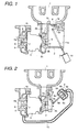
- FIG. 1 shows an embodiment (1).
- a turbine case 2 of exhaust turbo-supercharger is fixed to an exhaust manifold 1, exhaust gas is adiabatically expanded in the process of flowing from a turbine case inlet flow passage 2a into a turbine impeller 5 through a turbine scroll flow passage 2c and then flowing into a turbine case outlet flow passage 2b to rotate a compressor impeller 6.
- intake air is taken in through a compressor case inlet flow passage 4a, and kinetic energy of the intake air is converted to pressure in the compressor impeller 6 and the flow passage of the compressor case 4, and the compressed intake air is supplied to an engine through a compressor case outlet flow passage 4b.
- An exhaust bypass flow passage 1a arranged independently of and in parallel to the turbine scroll flow passage 2cfor guiding exhaust gas into the turbine impeller 5 is formed, and a valve seat plane 1b and an exhaust bypass valve 9 are provided in the an exhaust bypass flow passage 1a.
- Each of the exhaust bypass flow passage 1a, the valve seat plane 1b and the exhaust bypass valve 9 has a size large enough to be able to make almost all the amount of exhaust gas bypass the turbine 2.
- the exhaust bypass valve 9 is controlled to be opened and closed by a driving actuator 11 using a motor or a solenoid through a link 9a and a rod 11a.
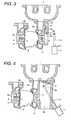
- FIG. 3 shows an embodiment (2).
- An exhaust bypass valve 9 and a valve seat plane 2e are provided in an exhaust bypass flow passage 2d which connects the turbine case inlet flow passage 2a for guiding exhaust gas to the turbine impeller 5 of the exhaust turbo-supercharger with the turbine case outlet flow passage 2b for discharging the exhaust gas passed through the turbine impeller 5 to the outside of the turbine case 2.
- Each of the exhaust bypass flow passage 2d, the valve seat plane 2e and the exhaust bypass valve 9 has a size large enough to be able to make almost all the amount of exhaust gas bypass the turbine 2.
- the exhaust bypass valve 9 is controlled to be opened and closed by a driving actuator using a motor through a link 9a and a rod 11a.
- FIG. 4 shows an embodiment (3).
- the present embodiment is an example in which the turbine case outlet flow passage 2b of the embodiment (1) is opened in the flowing direction of exhaust gas when the exhaust bypass valve 9 is opened.
- the catalyst is arranged just after the turbine case outlet flow passage 2b.
- temperature decrease of the exhaust gas is smaller than that of the embodiment (1).
- FIG. 5 shows an embodiment (4).
- the present embodiment is an example in which the exhaust manifold and the turbine case are integrated as a unit.
- the size of combination of the exhaust manifold and the turbine case can be made smaller and the volume of the exhaust flow passage from the combustion chamber of the internal combustion engine to the turbine impeller can be made smaller to improve the turbine work, and further fastening screws and fastening work to attaching the turbine to the exhaust manifold can be eliminated to decrease the cost.
- FIG. 6 shows an embodiment (5).
- the present embodiment is an example in which the turbine case 2 of the embodiment (1) is changed to a double wall structure to increase the thermal insulation effect of the turbine case 2.
- a methods of manufacturing the double wall structure there are a precision casting method through the lost-wax process and a plate material fabrication method.
- FIG. 7 shows an embodiment (5).
- the present embodiment is that in the embodiment (1), intake air flow passages 4c, 4d, 4e connecting the compressor case inlet flow passage 4a for guiding intake air to the compressor impeller 6 with the compressor outlet flow passage 4b for guiding the intake air passed through the compressor impeller 6 to the outside of the compressor case 4 are formed, and an intake bypass valve 12 and its valve seat 4f are provided in the intake bypass flow passage.
- the intake bypass valve 12 is controlled to be opened and closed by a driving actuator 13 using a motor or a solenoid valve through a link 12a and a rod 13a.
- the compressor impeller 6 When the exhaust bypass valve 9 is opened and the exhaust gas is bypassed in an operation mode not requiring supercharging, the compressor impeller 6 does not need to be rotated and the intake airflow passage sometimes becomes a flow resistance. In such a case, the intake resistance can be reduced by opening the intake bypass valve 12 to bypass the intake air.
- FIG. 8 shows an embodiment (7).
- the present embodiment has a structure that in the embodiment (1), a movable part 4g forming an R-profile of the compressor case 4 opposite to a blade outer peripheral R-profile portion of the compressor impeller 6 is movable in the axial direction of the turbine shaft 7.
- a cylinder member 4h is inserted into the compressor inlet flow passage 4a so that the flow passage volume of the compressor inlet flow passage 4a may be not largely changed by moving the movable part 4g.
- the movable part 4g is connected to a driving actuator 13 using a motor or a solenoid valve through a rod 13a to be controlled its displacement.
- the compressor impeller 6 When the exhaust bypass valve 9 is opened and the exhaust gas is bypassed in an operation mode not requiring supercharging, the compressor impeller 6 does not need to be rotated and the intake airflow passage sometimes becomes a flow resistance.
- the movable part 4g is moved in the axial direction of the turbine shaft in the direction apart from the blade outer peripheral R-profile portion of the compressor impeller 6 in the axial direction of the turbine shaft 7 to form a gap between the blade outer peripheral R-profile portion of the compressor impeller 6 and the R-profile of the compressor case 4 opposite to the blade outer R-profile portion. Therefore, the intake resistance can be reduced by bypassing the intake air using the gap.
- the intake bypass flow passage of the compressor portion can be made simpler than that of the embodiment (6) described above, and accordingly the compressor portion can be made small in size.
- FIG. 9 shows an embodiment (8).
- the embodiment (8) has a structure that in the embodiment (3), the opening area of the bypass flow passage is changed by inserting and extracting the exhaust bypass valve 9 into and from its opening portion.
- a guide of a rod 11a connecting between the exhaust bypass valve 9 and an actuator 11 is formed in the exhaust manifold 1.
- FIG. 10 shows an embodiment of an internal combustion engine system. Air is taken in from a compressor case inlet flow passage 4a through an air cleaner 15 using a compressor 4, and the compressed air is supplied from a compressor case outlet flow passage 4b to a combustion chamber of the internal combustion engine through an inter-cooler 16. Exhaust gas flows out from an exhaust manifold 1 to a turbine 2 through a turbine case inlet flow passage 2a, and then flows from a turbine case outlet flow passage 2b into a catalyst 17.
- FIG. 11 shows an example of steady-state performance characteristics of the internal combustion engine.
- Supercharging pressure becomes maximum when the exhaust bypass valve 9 is totally closed.
- the turbine inlet pressure is largely decreased (the points in the right hand side end in FIG. 11).
- the volumetric efficiency of the internal combustion engine is slightly improved.
- the ignition timing can be made to advance and the torque is also improved.
- the fuel flow rate can be reduced to improve the fuel consumption rate. Since the torque can be reduced in a range of operating mode where the accelerator pedal is not stepped in, the supercharging pressure can be reduced by opening the exhaust bypass valve in order to further improve the fuel economy.
- FIG. 12 shows an example of control of the exhaust bypass valve during a running state of a vehicle.
- the exhaust bypass valve is totally opened by judging that the accelerator pedal angle is zero and the engine speed is an idle setting rotation speed.
- the exhaust bypass valve is totally closed by judging from increasing rates of the accelerator pedal angle, the engine speed and the vehicle speed. Since the turbine is matched so that the low speed torque may become maximum, the acceleration performance of the vehicle can be improved compared to that in the prior art.
- fine angle control of the exhaust bypass valve is performed in order to prevent a shock caused by shifting of the speed change gear.
- the exhaust bypass valve is nearly totally opened to decrease the turbine inlet pressure and to improve the fuel consumption rate by judging form increasing rates of the accelerator pedal angle, the engine speed and the vehicle speed.
- the exhaust bypass valve is totally closed by judging that the accelerator pedal angle is maximum and the engine speed is the idle setting rotation speed.
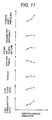
- FIG. 13 shows change in catalyst temperature after starting operation of the internal combustion engine.
- the temperature characteristic 18 shows temperature of the catalyst portion of the internal combustion engine without mounting any exhaust turbo-supercharger
- the temperature characteristic 19 shows temperature of the catalyst portion of the internal combustion engine with mounting an exhaust turbo-supercharger in which the temperature of the catalyst portion is lowered to approximately 40 % to 55 % of the temperature characteristic 18.
- the temperature characteristic 20 shows temperature of the catalyst portion of the internal combustion enginewith mounting the exhaust turbo-supercharger in accordance with the present invention, and the temperature of the catalyst portion is raised up to 80 % to 100 % of the temperature characteristic 18 because almost all the amount of exhaust gas passes through the exhaust bypass valve and flows into the catalyst.
- FIG. 2 shows a further embodiment.
- the turbine case 2 is fixed to an exhaust manifold 1, and exhaust gas is adiabatically expanded in the process that the exhaust gas flows form the turbine case inlet flow passage 2a into the turbine impeller 5 and is discharged to the turbine outlet flow passage 2b to rotate the compressor impeller 6 fixed to the turbine shaft 7.
- intake air is taken in through a compressor case inlet flow passage 4a, and kinetic energy of the intake air is converted to pressure in the compressor impeller 6 and the flow passage of the compressor case 4, and the compressed intake air is supplied to an engine through a compressor case outlet flow passage 4b.
- an exhaust bypass valve for controlling the supercharging pressure below a set supercharging pressure.
- the present embodiment comprises a mechanical actuator for controlling the exhaust bypass valve of this kind to open at starting operation of the engine.
- the mechanical actuator is divided into an atmospheric pressure chamber 8b and a pressure chamber 8c by a diaphragm 8a, and a rod 8d is fixed to the atmospheric pressure chamber 8b side of the diaphragm 8a, and the rod 8d is connected to a link 9a of the exhaust bypass valve 9.
- the pressure chamber 8c and the compressor case 4 are connected to each other by a hose 10 to allow the supercharging pressure entering into the pressure chamber 8c.
- a force caused by the supercharging pressure overcomes the force of a spring 8e to start to move the rod 8d and open the exhaust bypass valve 9.
- the present embodiment comprises a mechanism for forcibly opening the exhaust bypass valve at starting operation of the engine regardless of the supercharging pressure. Further, the opening area of the exhaust bypass flow passage 2d is determined so that when the exhaust bypass valve is controlled to be totally opened at starting operation of the engine, an amount of exhaust gas flowing into the turbine may essentially become minimum and can not practically rotate the turbine. In the other operation regions, the opening area of the exhaust bypass flow passage 2d is controlled to the totally closed state or in a specified small opening state by the exhaust bypass valve 9.
- the characteristic of the exhaust turbo-supercharger and the characteristic of the internal combustion engine are matched with each other so as to become the full load performance at a specified opening in which the exhaust bypass valve is partially closed from the totally opened state.
- the characteristic of the supercharging pressure in the partial load and the characteristic of the turbine inlet pressure are determined by the stroke characteristic of the actuator.
- twin scroll type variable capacity turbine As a technology, which further reduces the turbine pressure and improves the supercharging pressure characteristic and the turbine inlet pressure characteristic, a twin scroll type variable capacity turbine has been designed and practically used.
- nozzle vanes are arranged outside a turbine impeller, and a variable nozzle vane type variable capacity turbine of which the turbine capacity is varied by controlling an opening degree of the nozzle vanes and a turbine case flow passage are divided into two parts using a separating wall, and the turbine capacity is varied by controlling the opening of a switching valve provided in one side of the flow passage inlets.
- the present invention may be combined with this technology.
- FIG. 14 shows another embodiment in accordance with the present invention.
- a catalyst 21 is directly mounted into a straight pipe portion 1A of the exhaust passage provided in the turbine case 1. By doing so, the system can be made small in size.
- the turbine can be regarded as a turbine with catalyst, and accordingly, a new type turbine can be provided.
- an amount of heat removed from the exhaust gas by the turbine can be reduced, an amount of heat heating the catalyst is increased by that amount and accordingly the catalyst can be activated early.
- the system can be compactly formed.
Landscapes
- Engineering & Computer Science (AREA)
- Chemical & Material Sciences (AREA)
- Combustion & Propulsion (AREA)
- Mechanical Engineering (AREA)
- General Engineering & Computer Science (AREA)
- Chemical Kinetics & Catalysis (AREA)
- Health & Medical Sciences (AREA)
- Toxicology (AREA)
- Supercharger (AREA)
- Exhaust Gas After Treatment (AREA)
Applications Claiming Priority (2)
| Application Number | Priority Date | Filing Date | Title |
|---|---|---|---|
| JP2000394090A JP2002195046A (ja) | 2000-12-26 | 2000-12-26 | 内燃機関用排気タービン及び排気タービン式過給機 |
| JP2000394090 | 2000-12-26 |
Publications (2)
| Publication Number | Publication Date |
|---|---|
| EP1219799A2 true EP1219799A2 (fr) | 2002-07-03 |
| EP1219799A3 EP1219799A3 (fr) | 2002-09-11 |
Family
ID=18859775
Family Applications (1)
| Application Number | Title | Priority Date | Filing Date |
|---|---|---|---|
| EP01117759A Withdrawn EP1219799A3 (fr) | 2000-12-26 | 2001-07-31 | Turbine à gaz d'échappement pour moteurs à combustion interne et turbocompresseur de suralimentation |
Country Status (3)
| Country | Link |
|---|---|
| US (1) | US20020078934A1 (fr) |
| EP (1) | EP1219799A3 (fr) |
| JP (1) | JP2002195046A (fr) |
Cited By (6)
| Publication number | Priority date | Publication date | Assignee | Title |
|---|---|---|---|---|
| WO2008083769A1 (fr) * | 2006-12-21 | 2008-07-17 | Borgwarner Inc. | Ensemble de turbocompresseur étagé |
| DE102008045871A1 (de) * | 2008-09-04 | 2010-03-11 | Volkswagen Ag | Turbolader |
| EP2205841A1 (fr) * | 2007-10-29 | 2010-07-14 | Volkswagen Aktiengesellschaft | Moteur à combustion interne comprenant un turbocompresseur à gaz d'échappement et un refroidisseur d'air de suralimentation |
| RU2559207C1 (ru) * | 2014-02-21 | 2015-08-10 | Федеральное государственное бюджетное образовательное учреждение высшего профессионального образования Новосибирский государственный аграрный университет | Турбокомпрессор для наддува двигателей внутреннего сгорания |
| DE102015205966A1 (de) * | 2015-04-01 | 2016-10-20 | Volkswagen Aktiengesellschaft | Wastegateventilsystem, Abgasturbolader, Brennkraftmaschine und Kraftfahrzeug |
| WO2018068880A1 (fr) * | 2016-10-10 | 2018-04-19 | Ihi Charging Systems International Gmbh | Partie de guidage de gaz d'échappement pour un turbocompresseur à gaz d'échappement et ligne d'échappement pour un moteur à combustion interne ainsi que procédé de fonctionnement d'un turbocompresseur à gaz d'échappement |
Families Citing this family (58)
| Publication number | Priority date | Publication date | Assignee | Title |
|---|---|---|---|---|
| EP1418318A1 (fr) * | 2002-11-08 | 2004-05-12 | BorgWarner Inc. | Circuit pour un turbocompresseur |
| EP1700005B1 (fr) * | 2003-12-10 | 2014-12-03 | Honeywell International Inc. | Dispositif a buse variable pour turbocompresseur |
| JP2006274831A (ja) * | 2005-03-28 | 2006-10-12 | Denso Corp | ターボチャージャ付き内燃機関の制御装置 |
| US7562527B2 (en) | 2005-10-07 | 2009-07-21 | Toyota Jidosha Kabushiki Kaisha | Internal combustion engine with a supercharger |
| US20080066465A1 (en) * | 2006-09-20 | 2008-03-20 | Francis Andrew Maidens | Turbocharger header for an internal combustion engine |
| US7712311B2 (en) * | 2007-03-14 | 2010-05-11 | Gm Global Technology Operations, Inc. | Turbocharger assembly with catalyst coating |
| US8091357B2 (en) * | 2008-03-31 | 2012-01-10 | Caterpillar Inc. | System for recovering engine exhaust energy |
| JP2010025104A (ja) * | 2008-07-16 | 2010-02-04 | Borgwarner Inc | 後処理装置の受動的暖機制御用熱操作バイパス弁 |
| US20120017587A1 (en) * | 2009-04-10 | 2012-01-26 | Toyota Jidosha Kabushiki Kaisha | Control system of internal combustion engine |
| CN102405336A (zh) * | 2009-05-18 | 2012-04-04 | 博格华纳公司 | 内燃发动机 |
| US20110011082A1 (en) * | 2009-07-14 | 2011-01-20 | Southwest Research Institute | Emissions Control System Having External Turbocharger Wastegate and Integrated Oxidation Catalyst |
| JP5167217B2 (ja) * | 2009-09-02 | 2013-03-21 | 株式会社クボタ | ディーゼルエンジンの排気処理装置 |
| US9322327B2 (en) | 2009-11-03 | 2016-04-26 | Honeywell International Inc. | Turbocharger with bypass valve providing complete bypass of the turbine for improved catalyst light-off |
| JP5526853B2 (ja) * | 2010-02-22 | 2014-06-18 | トヨタ自動車株式会社 | ダイヤフラム型アクチュエータ |
| US9567950B2 (en) * | 2010-03-25 | 2017-02-14 | Ford Global Technologies, Llc | Turbocharged engine with naturally aspirated operating mode |
| US20130045082A1 (en) * | 2010-04-27 | 2013-02-21 | Borgwarner Inc. | Compressor of an exhaust-gas turbocharger |
| JP5655364B2 (ja) * | 2010-04-30 | 2015-01-21 | いすゞ自動車株式会社 | ターボ式過給機 |
| SE1150155A1 (sv) * | 2010-05-04 | 2011-11-05 | Alpraaz Ab | Avgassystem för en förbränningsmotor |
| US8549854B2 (en) * | 2010-05-18 | 2013-10-08 | Achates Power, Inc. | EGR constructions for opposed-piston engines |
| DE102010022736A1 (de) * | 2010-06-04 | 2011-12-08 | Mahle International Gmbh | Stellantrieb, Abgasrückführventil, Abgasturbolader |
| DE102010044683A1 (de) | 2010-09-08 | 2012-03-08 | Volkswagen Ag | Abgasturbolader mit einem Bypassventil |
| JP5454437B2 (ja) * | 2010-09-24 | 2014-03-26 | トヨタ自動車株式会社 | ウエストゲートバルブ装置 |
| US20130174548A1 (en) | 2011-05-16 | 2013-07-11 | Achates Power, Inc. | EGR for a Two-Stroke Cycle Engine without a Supercharger |
| US8528327B2 (en) * | 2011-05-18 | 2013-09-10 | GM Global Technology Operations LLC | Forced induction and exhaust system |
| JP5808152B2 (ja) * | 2011-05-26 | 2015-11-10 | ダイハツ工業株式会社 | 内燃機関の制御装置 |
| US10119549B2 (en) * | 2012-06-21 | 2018-11-06 | Borgwarner Inc. | Exhaust-gas turbocharger |
| JP6101797B2 (ja) * | 2012-06-21 | 2017-03-22 | ボーグワーナー インコーポレーテッド | 排気ガスターボチャージャ |
| US9714618B2 (en) | 2012-08-29 | 2017-07-25 | Ford Global Technologies, Llc | Method and system for improving starting of a turbocharged engine |
| US9014952B2 (en) | 2012-08-29 | 2015-04-21 | Ford Global Technologies, Llc | Method and system for improving stopping and starting of a turbocharged engine |
| US8925302B2 (en) | 2012-08-29 | 2015-01-06 | Ford Global Technologies, Llc | Method and system for operating an engine turbocharger |
| US9322289B2 (en) * | 2012-11-16 | 2016-04-26 | Ford Global Technologies, Llc | Vacuum-actuated wastegate |
| JP2015014258A (ja) | 2013-07-05 | 2015-01-22 | 株式会社Ihi | 過給機 |
| JP6289493B2 (ja) * | 2013-11-07 | 2018-03-07 | 本田技研工業株式会社 | 排気構造 |
| KR101593096B1 (ko) * | 2014-03-05 | 2016-02-11 | 주식회사 현대케피코 | 흡기 과급 시스템 및 그 제어방법 |
| GB2528097A (en) * | 2014-07-09 | 2016-01-13 | Jaguar Land Rover Ltd | Wastegate valve |
| GB2533351A (en) * | 2014-12-17 | 2016-06-22 | Gm Global Tech Operations Inc | Internal combustion engine having a two stage turbocharger |
| US9638098B2 (en) * | 2015-02-17 | 2017-05-02 | Electro-Motive Diesel, Inc. | Bypass mechanism for an exhaust system |
| DE102016200923A1 (de) | 2016-01-22 | 2017-07-27 | Ford Global Technologies, Llc | Regelung der Abgastemperatur durch elektrische Turbine |
| US10294878B2 (en) * | 2016-02-24 | 2019-05-21 | GM Global Technology Operations LLC | Wastegate control systems and methods for engine sound emission |
| JP6792432B2 (ja) * | 2016-11-30 | 2020-11-25 | ダイハツ工業株式会社 | 内燃機関 |
| US10428727B2 (en) * | 2017-04-14 | 2019-10-01 | Ford Motor Company | Bonding strength enhancement for ceramic coating on high temperature alloy |
| DE102017218297A1 (de) * | 2017-10-12 | 2019-04-18 | Continental Automotive Gmbh | Ventilklappeneinrichtung für ein Bypass-Ventil eines Abgasturboladers sowie Abgasturbolader |
| DE102018217510A1 (de) * | 2018-10-12 | 2020-04-16 | BMTS Technology GmbH & Co. KG | Verdichter und ein Verfahren zur Montage einer Verstellvorrichtung in dem Verdichter |
| US11352935B2 (en) | 2018-12-07 | 2022-06-07 | Polaris Industries Inc. | Exhaust system for a vehicle |
| US20200182164A1 (en) | 2018-12-07 | 2020-06-11 | Polaris Industries Inc. | Method And System For Predicting Trapped Air Mass In A Two-Stroke Engine |
| US11131235B2 (en) | 2018-12-07 | 2021-09-28 | Polaris Industries Inc. | System and method for bypassing a turbocharger of a two stroke engine |
| US11280258B2 (en) * | 2018-12-07 | 2022-03-22 | Polaris Industries Inc. | Exhaust gas bypass valve system for a turbocharged engine |
| US11236668B2 (en) | 2018-12-07 | 2022-02-01 | Polaris Industries Inc. | Method and system for controlling pressure in a tuned pipe of a two stroke engine |
| US11725573B2 (en) | 2018-12-07 | 2023-08-15 | Polaris Industries Inc. | Two-passage exhaust system for an engine |
| US11174779B2 (en) | 2018-12-07 | 2021-11-16 | Polaris Industries Inc. | Turbocharger system for a two-stroke engine |
| US11639684B2 (en) | 2018-12-07 | 2023-05-02 | Polaris Industries Inc. | Exhaust gas bypass valve control for a turbocharger for a two-stroke engine |
| US11828239B2 (en) | 2018-12-07 | 2023-11-28 | Polaris Industries Inc. | Method and system for controlling a turbocharged two stroke engine based on boost error |
| CA3217527A1 (fr) | 2020-01-13 | 2021-07-13 | Polaris Industries Inc. | Circuit de lubrification de turbocompresseur pour un moteur a deux temps |
| US11788432B2 (en) | 2020-01-13 | 2023-10-17 | Polaris Industries Inc. | Turbocharger lubrication system for a two-stroke engine |
| CA3201948A1 (fr) | 2020-01-13 | 2021-07-13 | Polaris Industries Inc. | Systeme de turbocompresseur pour un moteur a deux temps ayant des modes surpresseurs a selectionner |
| US11384697B2 (en) | 2020-01-13 | 2022-07-12 | Polaris Industries Inc. | System and method for controlling operation of a two-stroke engine having a turbocharger |
| US11473494B1 (en) | 2021-04-01 | 2022-10-18 | Ford Global Technologies, Llc | Methods and systems for turbine bypass |
| US11572815B2 (en) | 2021-06-11 | 2023-02-07 | Ford Global Technologies, Llc | Methods and systems for turbine bypass |
Citations (2)
| Publication number | Priority date | Publication date | Assignee | Title |
|---|---|---|---|---|
| JPS60237153A (ja) | 1984-05-09 | 1985-11-26 | Fuji Heavy Ind Ltd | 過給機付エンジンのegr装置 |
| JPH0390536A (ja) | 1989-08-31 | 1991-04-16 | Nippon Stainless Steel Co Ltd | 高強度非磁性ステンレス鋼 |
Family Cites Families (9)
| Publication number | Priority date | Publication date | Assignee | Title |
|---|---|---|---|---|
| JPS57126516A (en) * | 1981-01-30 | 1982-08-06 | Fuji Heavy Ind Ltd | Internal combustion engine with supercharger |
| FR2606075B1 (fr) * | 1986-10-29 | 1990-12-21 | Peugeot | Dispositif de commande de l'echappement des gaz a la sortie d'un moteur suralimente par un turbocompresseur |
| JPH04103817A (ja) * | 1990-08-22 | 1992-04-06 | Ishikawajima Harima Heavy Ind Co Ltd | 自動車用過給機の排気供給方法及びその装置 |
| JPH04370327A (ja) * | 1991-06-17 | 1992-12-22 | Honda Motor Co Ltd | 可変容量型ターボチャージャの制御方法 |
| DE4311904C2 (de) * | 1993-04-10 | 2000-06-29 | Audi Ag | Vorrichtung an einer Brennkraftmaschine |
| DE19503748A1 (de) * | 1995-02-04 | 1996-06-20 | Daimler Benz Ag | Verbrennungsmotor |
| FR2752880B1 (fr) * | 1996-08-30 | 1998-09-25 | Renault | Dispositif de suralimentation pour moteur a combustion interne |
| DE19654026A1 (de) * | 1996-12-21 | 1998-06-25 | Porsche Ag | Abgasanlage für eine aufgeladene Brennkraftmaschine |
| WO1998045589A1 (fr) * | 1997-04-07 | 1998-10-15 | Siemens Electromechanical Components, Inc. | Alternateur a turbine entraine par des gaz d'echappement |
-
2000
- 2000-12-26 JP JP2000394090A patent/JP2002195046A/ja active Pending
-
2001
- 2001-07-31 EP EP01117759A patent/EP1219799A3/fr not_active Withdrawn
- 2001-08-31 US US09/943,450 patent/US20020078934A1/en not_active Abandoned
Patent Citations (2)
| Publication number | Priority date | Publication date | Assignee | Title |
|---|---|---|---|---|
| JPS60237153A (ja) | 1984-05-09 | 1985-11-26 | Fuji Heavy Ind Ltd | 過給機付エンジンのegr装置 |
| JPH0390536A (ja) | 1989-08-31 | 1991-04-16 | Nippon Stainless Steel Co Ltd | 高強度非磁性ステンレス鋼 |
Cited By (8)
| Publication number | Priority date | Publication date | Assignee | Title |
|---|---|---|---|---|
| WO2008083769A1 (fr) * | 2006-12-21 | 2008-07-17 | Borgwarner Inc. | Ensemble de turbocompresseur étagé |
| CN101548083B (zh) * | 2006-12-21 | 2011-04-06 | 博格华纳公司 | 多级涡轮增压器安排 |
| US8407997B2 (en) | 2006-12-21 | 2013-04-02 | Borgwarner Inc. | Multistep turbocharger arrangement |
| EP2205841A1 (fr) * | 2007-10-29 | 2010-07-14 | Volkswagen Aktiengesellschaft | Moteur à combustion interne comprenant un turbocompresseur à gaz d'échappement et un refroidisseur d'air de suralimentation |
| DE102008045871A1 (de) * | 2008-09-04 | 2010-03-11 | Volkswagen Ag | Turbolader |
| RU2559207C1 (ru) * | 2014-02-21 | 2015-08-10 | Федеральное государственное бюджетное образовательное учреждение высшего профессионального образования Новосибирский государственный аграрный университет | Турбокомпрессор для наддува двигателей внутреннего сгорания |
| DE102015205966A1 (de) * | 2015-04-01 | 2016-10-20 | Volkswagen Aktiengesellschaft | Wastegateventilsystem, Abgasturbolader, Brennkraftmaschine und Kraftfahrzeug |
| WO2018068880A1 (fr) * | 2016-10-10 | 2018-04-19 | Ihi Charging Systems International Gmbh | Partie de guidage de gaz d'échappement pour un turbocompresseur à gaz d'échappement et ligne d'échappement pour un moteur à combustion interne ainsi que procédé de fonctionnement d'un turbocompresseur à gaz d'échappement |
Also Published As
| Publication number | Publication date |
|---|---|
| US20020078934A1 (en) | 2002-06-27 |
| JP2002195046A (ja) | 2002-07-10 |
| EP1219799A3 (fr) | 2002-09-11 |
Similar Documents
| Publication | Publication Date | Title |
|---|---|---|
| EP1219799A2 (fr) | Turbine à gaz d'échappement pour moteurs à combustion interne et turbocompresseur de suralimentation | |
| US7950227B2 (en) | High response compact turbocharger | |
| JP4596192B2 (ja) | 排気ガスターボチャージャを有する内燃機関 | |
| JP5464607B2 (ja) | ピストン往復内燃機関のための給気制御装置、ピストン往復内燃機関のための給気制御装置に用いられる弁、および、ピストン往復内燃機関の運動を制御するための方法 | |
| US7246490B2 (en) | Internal combustion engine including a compressor and method for operating an internal combustion engine | |
| CN102913317B (zh) | 具有两个涡轮的增压内燃发动机和用于运行所述类型内燃发动机的方法 | |
| US6739134B2 (en) | Exhaust gas turbocharger for an internal combustion engine | |
| JP2008520882A (ja) | 排ガスターボチャージャ付き内燃機関 | |
| JP2006097684A (ja) | Vtgタービン段を利用する多段ターボ過給装置 | |
| US20080066466A1 (en) | Device for accelerating a turbocharger unit at low speeds of a reciprocating engine, and a reciprocating engine including such a device | |
| JP2012504202A (ja) | 内燃機関のための排気ターボチャージャ | |
| JP2009534569A (ja) | 調節可能なタービン形状と羽根保持リングの圧力補償開口部を有するターボチャージャ | |
| JP2010508467A (ja) | 内燃機関用ターボチャージャ | |
| JP2013509521A (ja) | 調整可能なタービンジオメトリを備えるエグゾーストターボチャージャのガイド装置及び内燃機関のエグゾーストターボチャージャ | |
| US4822242A (en) | Variable capacity turbo supercharger | |
| JPS6296734A (ja) | タ−ボ過給機 | |
| KR102156152B1 (ko) | 내연기관 작동 방법 및 내연기관 | |
| JP2007255381A (ja) | 遠心圧縮機およびこれを用いたエンジンの吸気制御システムならびに吸気制御方法 | |
| JP2007120383A (ja) | ターボチャージャ | |
| JPH0444088B2 (fr) | ||
| US11629612B2 (en) | System for feeding operating gas to a drive of a motor vehicle | |
| JPH1089081A (ja) | 可変容量ターボチャージャの過給圧制御装置 | |
| JP2017089390A (ja) | 内燃機関の吸気装置 | |
| JP7738768B2 (ja) | 特に自動車の排ガスターボチャージャのためのタービン、及び内燃機関 | |
| JP2004211649A (ja) | Egrクーラシステム |
Legal Events
| Date | Code | Title | Description |
|---|---|---|---|
| PUAI | Public reference made under article 153(3) epc to a published international application that has entered the european phase |
Free format text: ORIGINAL CODE: 0009012 |
|
| AK | Designated contracting states |
Kind code of ref document: A2 Designated state(s): AT BE CH CY DE DK ES FI FR GB GR IE IT LI LU MC NL PT SE TR |
|
| AX | Request for extension of the european patent |
Free format text: AL;LT;LV;MK;RO;SI |
|
| PUAL | Search report despatched |
Free format text: ORIGINAL CODE: 0009013 |
|
| AK | Designated contracting states |
Kind code of ref document: A3 Designated state(s): AT BE CH CY DE DK ES FI FR GB GR IE IT LI LU MC NL PT SE TR |
|
| AX | Request for extension of the european patent |
Free format text: AL;LT;LV;MK;RO;SI |
|
| 17P | Request for examination filed |
Effective date: 20030108 |
|
| AKX | Designation fees paid |
Designated state(s): DE FR GB IT |
|
| STAA | Information on the status of an ep patent application or granted ep patent |
Free format text: STATUS: THE APPLICATION HAS BEEN WITHDRAWN |
|
| 18W | Application withdrawn |
Effective date: 20080306 |