EP1219904A2 - Hotte aspirante de buée - Google Patents
Hotte aspirante de buée Download PDFInfo
- Publication number
- EP1219904A2 EP1219904A2 EP01128910A EP01128910A EP1219904A2 EP 1219904 A2 EP1219904 A2 EP 1219904A2 EP 01128910 A EP01128910 A EP 01128910A EP 01128910 A EP01128910 A EP 01128910A EP 1219904 A2 EP1219904 A2 EP 1219904A2
- Authority
- EP
- European Patent Office
- Prior art keywords
- extractor hood
- power
- connection
- wall
- lighting system
- Prior art date
- Legal status (The legal status is an assumption and is not a legal conclusion. Google has not performed a legal analysis and makes no representation as to the accuracy of the status listed.)
- Withdrawn
Links
Images
Classifications
-
- F—MECHANICAL ENGINEERING; LIGHTING; HEATING; WEAPONS; BLASTING
- F24—HEATING; RANGES; VENTILATING
- F24C—DOMESTIC STOVES OR RANGES ; DETAILS OF DOMESTIC STOVES OR RANGES, OF GENERAL APPLICATION
- F24C15/00—Details
- F24C15/20—Removing cooking fumes
- F24C15/2064—Removing cooking fumes illumination for cooking hood
Definitions
- the invention relates to an extractor hood, preferably in or between Kitchen cabinets can be mounted.
- Extractor hoods have a power connection through which the internal lighting and the fan system are operated. When installing, the power connection with a stationary wall connection via a plug connection or a Direct connection connected. Likewise with an existing lighting system z. B. below kitchen top cabinets. Thus, if there is an extractor hood and existing kitchen wall cabinets with lighting system at least two stationary wall connections necessary.
- plug strips or Adapters If there is only one wall connection, you can use so-called plug strips or Adapters. These need space. This is a major disadvantage. Alternatively, one would be to mount the second wall connection. That could lead to trouble. A hollow bar for the cable on tiled walls is unacceptable and laying under tiles there are often limits because, for example, replacement tiles are missing.
- the object of the invention is the lighting system of kitchen cabinets, in particular Kitchen wall cabinets and the power supply of an extractor hood from to operate from a wall connection. This task is solved with the characteristics of claim 1, advantageous embodiments are the subject of the dependent claims.
- the extractor hood according to the invention which in or between kitchen wall cabinets can be installed and via a power connection for the internal lighting of the extractor hood has, the power connection supplied via a wall connection provides that one or more power distributors in the extractor hood are arranged, which are connected to the power connection of the extractor hood and the connectable to the power connection of a lighting system of the kitchen wall cabinets are so that the lighting system of the kitchen wall cabinets from a wall connection Can be supplied via the power connection of the extractor hood and the power distributor is or the power connection of the extractor hood from a wall connection the power connection of the lighting system of the kitchen wall cabinets and the power distributor is available. So for the lighting system of kitchen cabinets, in particular Kitchen wall cabinets and the power supply of an extractor hood only a wall connection is required.
- the invention provides that the power distributor a separate opening in the extractor hood is accessible from the outside.
- This opening is preferably arranged laterally in the extractor hood and completely with a cover or partially lockable.
- the lid is preferably pre-punched so that the required openings in the lid can be broken out.
- the invention provides that the connection the power connection of the lighting system with the power distributor via a Switch in the extractor hood is switchable. Especially when retrofitting of a lighting system under kitchen wall cabinets is the problem of attachment a switch already resolved. Its position is obvious, obvious and ergonomically favorable.
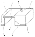
- FIG. 1 An embodiment of the invention is shown in the drawing.
- the figure shows one Extractor hood 1, which is mounted between two kitchen wall cabinets 2.
- the extractor hood 1 has a power connector for internal lighting and that Fan system and is supplied by a wall connection, not shown.
- a power distributor 5 which is connected to the power connector the extractor hood 1 is connected.
- the power distributor 5 is on the side in the extractor hood 1 via a separate opening accessible from the outside.
- the opening is with a lid completely or partially lockable. Fully lockable makes sense if the power distributor 5 is not required. In the event of partial locking, there remains a cable passage receive or the opening for one or more plug connections.
- the lighting system 3 which is below the kitchen wall cabinets 2 behind a bar 4 is arranged, does not have its own wall connection.
- the power connection of the Lighting system 3 is with the power distributor 5, which has one or more connectors connected, and is thus from a wall connection to the power connection the extractor hood 1 and the power distributor 5 supplied.
- the connection of the Power connection of the lighting system 3 with the power distributor 5 is on the Switch 6 in the extractor hood 1 can be switched.
Landscapes
- Engineering & Computer Science (AREA)
- Chemical & Material Sciences (AREA)
- Combustion & Propulsion (AREA)
- Mechanical Engineering (AREA)
- General Engineering & Computer Science (AREA)
- Ventilation (AREA)
- Combinations Of Kitchen Furniture (AREA)
Applications Claiming Priority (2)
| Application Number | Priority Date | Filing Date | Title |
|---|---|---|---|
| DE20021711U DE20021711U1 (de) | 2000-12-22 | 2000-12-22 | Dunstabzugshaube |
| DE20021711U | 2000-12-22 |
Publications (2)
| Publication Number | Publication Date |
|---|---|
| EP1219904A2 true EP1219904A2 (fr) | 2002-07-03 |
| EP1219904A3 EP1219904A3 (fr) | 2002-09-25 |
Family
ID=7950424
Family Applications (1)
| Application Number | Title | Priority Date | Filing Date |
|---|---|---|---|
| EP01128910A Withdrawn EP1219904A3 (fr) | 2000-12-22 | 2001-12-05 | Hotte aspirante de buée |
Country Status (2)
| Country | Link |
|---|---|
| EP (1) | EP1219904A3 (fr) |
| DE (1) | DE20021711U1 (fr) |
Cited By (1)
| Publication number | Priority date | Publication date | Assignee | Title |
|---|---|---|---|---|
| EP1729068A1 (fr) * | 2005-05-31 | 2006-12-06 | Greenwood Air Management Limited | Unité combinée de ventilation et lumière |
Families Citing this family (1)
| Publication number | Priority date | Publication date | Assignee | Title |
|---|---|---|---|---|
| CN107314411A (zh) * | 2017-04-04 | 2017-11-03 | 温岭市兴庆机械设备有限公司 | 一种新型油烟净化装置 |
Family Cites Families (6)
| Publication number | Priority date | Publication date | Assignee | Title |
|---|---|---|---|---|
| US2971451A (en) * | 1958-06-16 | 1961-02-14 | Progress Mfg Company | Ventilator unit |
| DE2551865A1 (de) | 1975-11-19 | 1977-06-02 | Gaggenau Werke | Einbau-dunstabzug fuer abzugshauben |
| DE7911135U1 (de) | 1979-04-17 | 1979-08-30 | Pfeifer Ohg Fabrik Fuer Beleuchtungskoerper Und Metallwaren Und Handelsgeschaeft, 3565 Breidenbach | Dunstabzugs- und beleuchtungs- einbauelement |
| DE8033000U1 (de) | 1980-12-12 | 1981-09-17 | Gebrüder Mayer KG, 5760 Arnsberg | Bausatz, insbesondere fuer einbau-dunstabzugshauben |
| DE3046751A1 (de) * | 1980-12-12 | 1982-07-15 | Gebrüder Mayer KG, 5760 Arnsberg | Beleuchtungseinrichtung, insbesondere an einbau-dunstabzugshauben |
| DE3341068A1 (de) * | 1983-11-12 | 1985-05-23 | Licentia Patent-Verwaltungs-Gmbh, 6000 Frankfurt | Dunstabzugs- oder -filterhaube |
-
2000
- 2000-12-22 DE DE20021711U patent/DE20021711U1/de not_active Expired - Lifetime
-
2001
- 2001-12-05 EP EP01128910A patent/EP1219904A3/fr not_active Withdrawn
Cited By (1)
| Publication number | Priority date | Publication date | Assignee | Title |
|---|---|---|---|---|
| EP1729068A1 (fr) * | 2005-05-31 | 2006-12-06 | Greenwood Air Management Limited | Unité combinée de ventilation et lumière |
Also Published As
| Publication number | Publication date |
|---|---|
| DE20021711U1 (de) | 2001-02-15 |
| EP1219904A3 (fr) | 2002-09-25 |
Similar Documents
| Publication | Publication Date | Title |
|---|---|---|
| DE69607399T2 (de) | Küchenhaube mit Abzug- und/oder Filteranlage | |
| DE10114729A1 (de) | Schaltschrank mit einer Rauchmeldeeinrichtung | |
| DE3722282A1 (de) | Vorrichtung zur waermebehandlung von nahrungsmitteln | |
| DE29706187U1 (de) | Vorrichtung zum Entfernen von Staub von Computern o.dgl. Geräten | |
| DE60128690T2 (de) | Dieselkraftstofffilter mit austauschbarem filtereinsatz | |
| EP1219904A2 (fr) | Hotte aspirante de buée | |
| DE69417461T2 (de) | Reinigungssysteme mit kontrollierten Rühren | |
| DE4428197C2 (de) | Elektrisch betreibbare Waschmaschine | |
| DE102008023311A1 (de) | Umluftweiche sowie Verfahren zum Montieren einer Umluftweiche | |
| DE202016104282U1 (de) | Downdraft-Abzugshaube mit reduziertem Raumbedarf | |
| EP2074915B1 (fr) | Appareil ménager électrique | |
| DE2407448C3 (de) | Anlage zur Lüftung bzw. Klimatisierung von Räumen | |
| DE202015000867U1 (de) | Netzwerkstecker | |
| DE60202835T2 (de) | Wandmontierbarer Mikrowellenofen | |
| AT391259B (de) | Dunstabzugshaube | |
| EP0030400A1 (fr) | Epurateur d'air | |
| DE29714127U1 (de) | Dampfabzugsvorrichtung | |
| DE202004020333U1 (de) | Ablufthaube | |
| DE7736836U1 (de) | Arbeitstisch mit Kabelkanälen | |
| DE202016104280U1 (de) | Vertikale Abzugshaube mit reduziertem Raumbedarf | |
| EP2955450B1 (fr) | Hotte aspirante | |
| DE10057943A1 (de) | Gastherme oder Gasbrennwerttherme | |
| DE2551865A1 (de) | Einbau-dunstabzug fuer abzugshauben | |
| DE102015106764A1 (de) | Abdeckrahmen, Gehäusebasis und Gehäuse für eine Geräteeinheit eines Haushaltsgeräts sowie Montageverfahren zum Montieren und Demontageverfahren zum Demontieren eines Gehäuses für eine Geräteeinheit eines Haushaltsgeräts | |
| EP0655816B1 (fr) | Dispositif de montage |
Legal Events
| Date | Code | Title | Description |
|---|---|---|---|
| PUAI | Public reference made under article 153(3) epc to a published international application that has entered the european phase |
Free format text: ORIGINAL CODE: 0009012 |
|
| AK | Designated contracting states |
Kind code of ref document: A2 Designated state(s): AT BE CH CY DE DK ES FI FR GB GR IE IT LI LU MC NL PT SE TR |
|
| AX | Request for extension of the european patent |
Free format text: AL;LT;LV;MK;RO;SI |
|
| PUAL | Search report despatched |
Free format text: ORIGINAL CODE: 0009013 |
|
| AK | Designated contracting states |
Kind code of ref document: A3 Designated state(s): AT BE CH CY DE DK ES FI FR GB GR IE IT LI LU MC NL PT SE TR |
|
| AX | Request for extension of the european patent |
Free format text: AL;LT;LV;MK;RO;SI |
|
| 17P | Request for examination filed |
Effective date: 20030325 |
|
| AKX | Designation fees paid |
Designated state(s): AT BE CH CY DE DK ES FI FR GB GR IE IT LI LU MC NL PT SE TR |
|
| RAP1 | Party data changed (applicant data changed or rights of an application transferred) |
Owner name: BSH BOSCH UND SIEMENS HAUSGERAETE GMBH |
|
| RTI1 | Title (correction) |
Free format text: ARRANGEMENT WITH A SMOKE EXTRACTING HOOD |
|
| GRAP | Despatch of communication of intention to grant a patent |
Free format text: ORIGINAL CODE: EPIDOSNIGR1 |
|
| STAA | Information on the status of an ep patent application or granted ep patent |
Free format text: STATUS: THE APPLICATION IS DEEMED TO BE WITHDRAWN |
|
| 18D | Application deemed to be withdrawn |
Effective date: 20070116 |