EP1219918A2 - Position-Wandler - Google Patents
Position-Wandler Download PDFInfo
- Publication number
- EP1219918A2 EP1219918A2 EP01309592A EP01309592A EP1219918A2 EP 1219918 A2 EP1219918 A2 EP 1219918A2 EP 01309592 A EP01309592 A EP 01309592A EP 01309592 A EP01309592 A EP 01309592A EP 1219918 A2 EP1219918 A2 EP 1219918A2
- Authority
- EP
- European Patent Office
- Prior art keywords
- mobile unit
- base unit
- coupling line
- guide arm
- transducer
- Prior art date
- Legal status (The legal status is an assumption and is not a legal conclusion. Google has not performed a legal analysis and makes no representation as to the accuracy of the status listed.)
- Withdrawn
Links
Images


Classifications
-
- G—PHYSICS
- G01—MEASURING; TESTING
- G01D—MEASURING NOT SPECIALLY ADAPTED FOR A SPECIFIC VARIABLE; ARRANGEMENTS FOR MEASURING TWO OR MORE VARIABLES NOT COVERED IN A SINGLE OTHER SUBCLASS; TARIFF METERING APPARATUS; MEASURING OR TESTING NOT OTHERWISE PROVIDED FOR
- G01D5/00—Mechanical means for transferring the output of a sensing member; Means for converting the output of a sensing member to another variable where the form or nature of the sensing member does not constrain the means for converting; Transducers not specially adapted for a specific variable
- G01D5/12—Mechanical means for transferring the output of a sensing member; Means for converting the output of a sensing member to another variable where the form or nature of the sensing member does not constrain the means for converting; Transducers not specially adapted for a specific variable using electric or magnetic means
- G01D5/14—Mechanical means for transferring the output of a sensing member; Means for converting the output of a sensing member to another variable where the form or nature of the sensing member does not constrain the means for converting; Transducers not specially adapted for a specific variable using electric or magnetic means influencing the magnitude of a current or voltage
- G01D5/16—Mechanical means for transferring the output of a sensing member; Means for converting the output of a sensing member to another variable where the form or nature of the sensing member does not constrain the means for converting; Transducers not specially adapted for a specific variable using electric or magnetic means influencing the magnitude of a current or voltage by varying resistance
- G01D5/165—Mechanical means for transferring the output of a sensing member; Means for converting the output of a sensing member to another variable where the form or nature of the sensing member does not constrain the means for converting; Transducers not specially adapted for a specific variable using electric or magnetic means influencing the magnitude of a current or voltage by varying resistance by relative movement of a point of contact or actuation and a resistive track
-
- G—PHYSICS
- G01—MEASURING; TESTING
- G01B—MEASURING LENGTH, THICKNESS OR SIMILAR LINEAR DIMENSIONS; MEASURING ANGLES; MEASURING AREAS; MEASURING IRREGULARITIES OF SURFACES OR CONTOURS
- G01B7/00—Measuring arrangements characterised by the use of electric or magnetic techniques
- G01B7/003—Measuring arrangements characterised by the use of electric or magnetic techniques for measuring position, not involving coordinate determination
-
- G—PHYSICS
- G01—MEASURING; TESTING
- G01D—MEASURING NOT SPECIALLY ADAPTED FOR A SPECIFIC VARIABLE; ARRANGEMENTS FOR MEASURING TWO OR MORE VARIABLES NOT COVERED IN A SINGLE OTHER SUBCLASS; TARIFF METERING APPARATUS; MEASURING OR TESTING NOT OTHERWISE PROVIDED FOR
- G01D5/00—Mechanical means for transferring the output of a sensing member; Means for converting the output of a sensing member to another variable where the form or nature of the sensing member does not constrain the means for converting; Transducers not specially adapted for a specific variable
- G01D5/02—Mechanical means for transferring the output of a sensing member; Means for converting the output of a sensing member to another variable where the form or nature of the sensing member does not constrain the means for converting; Transducers not specially adapted for a specific variable using mechanical means
- G01D5/04—Mechanical means for transferring the output of a sensing member; Means for converting the output of a sensing member to another variable where the form or nature of the sensing member does not constrain the means for converting; Transducers not specially adapted for a specific variable using mechanical means using levers; using cams; using gearing
-
- G—PHYSICS
- G06—COMPUTING OR CALCULATING; COUNTING
- G06F—ELECTRIC DIGITAL DATA PROCESSING
- G06F3/00—Input arrangements for transferring data to be processed into a form capable of being handled by the computer; Output arrangements for transferring data from processing unit to output unit, e.g. interface arrangements
- G06F3/01—Input arrangements or combined input and output arrangements for interaction between user and computer
- G06F3/03—Arrangements for converting the position or the displacement of a member into a coded form
- G06F3/033—Pointing devices displaced or positioned by the user, e.g. mice, trackballs, pens or joysticks; Accessories therefor
- G06F3/0346—Pointing devices displaced or positioned by the user, e.g. mice, trackballs, pens or joysticks; Accessories therefor with detection of the device orientation or free movement in a three-dimensional [3D] space, e.g. 3D mice, 6-DOF [six degrees of freedom] pointers using gyroscopes, accelerometers or tilt-sensors
-
- H—ELECTRICITY
- H04—ELECTRIC COMMUNICATION TECHNIQUE
- H04R—LOUDSPEAKERS, MICROPHONES, GRAMOPHONE PICK-UPS OR LIKE ACOUSTIC ELECTROMECHANICAL TRANSDUCERS; ELECTRIC HEARING AIDS; PUBLIC ADDRESS SYSTEMS
- H04R29/00—Monitoring arrangements; Testing arrangements
Definitions
- This invention relates to a position transducer for detecting position in three generally orthogonal directions.
- a base unit a mobile unit movable relative to the base unit, a generally tubular elongate guide arm fixed to the base unit and arranged to be angularly movable such that it in use, it extends generally towards the mobile unit, and a variable length coupling line passing through the guide arm and fixed to the mobile unit at its distal end, the transducer being operable to output information about the angular position of the guide arm and the extended length of the coupling line from which information, the relative positions of the base unit and mobile unit are calculable.
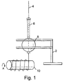
- the transducer has a base unit 2 and a mobile unit (not shown) fixed to the distal end of a variable length coupling line 4.
- the coupling line 4 passes through a generally tubular elongate guide arm 6 and through a ball 8 and is then wound onto a drum 10.
- the drum 10 is spring loaded so that it is biased to rotate in the direction of arrow A.
- the coupling line 4 is extended outwardly through the guide arm 6, the line is unwound from the drum 10.
- the unwinding motion is resisted by the spring loading and therefore if the pulling force on the line 4 is reduced, the line is rewound onto the drum 10 under the action of the spring load biasing force.
- the ball 8 is mounted in bearings (not shown) so that the guide arm is articulated. This means that if the angular position of the cord relative to the base unit 2 is varied, the guide arm 6 tends to follow the direction of extension of the coupling line 4.
- the angular position of the ball 8 (and therefore the direction of extension of the guide arm 6) is sensed in two axes x and y.
- the sensing may be performed using optical means (by putting a light source and a light detector on opposite sides of a slotted wheel 12-2 and 12-4 as shown) or using other means such as rotary potentiometers. It will be appreciated that techniques presently used in sensing the movement of a ball in a computer mouse or sensing movement in a computer joystick may be applied to the problem of measuring the angular position of the ball 8.
- the angular position of the drum 10 may also be sensed using similar techniques by, for example, putting a slotted disc 12-6 at one end of the axle of the drum 10. In this way, the extended length or change in the length, of the coupling line 4 may be monitored or measured.
- the position of the mobile unit at the distal end of the coupling line 4 may be determined along the axis passing generally through the centre of the guide arm (marked z in the drawings) using the measurement at the axle of the drum 10.
- the angular direction of extension of the guide arm and of the coupling line 4 may be determined using the sensors 12-2 and 12-4.
- the position of the mobile unit relative to the base unit 2 may be uniquely be determined along the x y and z axes.
- the base unit on the floor or on a table and attaching the mobile unit to an operator's hand (for example by forming the mobile unit as a glove which may be put on the operator's hand), movements of the operator's hand may be tracked by monitoring the positions of the sensors 12-2, 12-4 and 12-6.
- the base unit 2 may be desirable to allow the base unit 2 to impart movement to the mobile unit for example, to provide a so-called "force feedback” sensation.
- This may be achieved, for example by driving the drum 10 so that the mobile unit is pulled and released in accordance with the driving motion applied to the drum axle 14.
- the ball 8 may be driven in one or both axes as shown in Figure 4.
- position sensing of the ball 8 is achieved using a rotatable rod 16 which is rotated by frictional contact with the ball 8 via a resilient sleeve 18.
- An actuator 20 at one end of the rod 16 may also rotate the rod 16 and thereby impart motion to the ball 8.
- this motion is directly read by the position sensor 12-2 or 12-4 which therefore allows apparatus attempting to interpret the outputs of the position sensors 12 to recognise movement resulting from the actuator 20 as opposed to movement resulting from the mobile unit being moved.
- a mobile unit 20 is attached to the distal end of the coupling line 4.
- the lower end of the mobile unit 20 preferably has a plastic or other low friction material, sheath around the coupling line 4 to reduce wear on the coupling line.
- the sheath is marked with the reference numeral 22.
- the coupling line 4 passes through a funnel-shaped cable guide 24 which ensures that the angle between the coupling line 4 and the base 26 of the mobile unit 20 does not become too acute and which also allows a "joystick assembly" 28 to monitor or measure the angle between the coupling line 4 and the mobile unit 20 in a similar manner to the guide arm 6 on the base unit 2.
- the "joystick assembly" 28 operates to measure the angle between the coupling line 4 and the mobile unit 20. This information may be passed back down the coupling line 4 (which may incorporate electrical conductors for this purpose) so that angular movements (for example rotational movements) of the mobile unit 20 which do not result in corresponding movement between the coupling line 4 and the base unit 2, may be monitored or measured.
- the mobile unit may for example be in the form of a sword.
- the coupling line may enter the sword in the region of the handle of the sword and the joystick assembly may be used to detect rotation of the sword both about its longitudinal axis and along its longitudinal axis. This, for example, allows the position of the point of the sword to be determined relative to the base unit 2.
- a similar technique may be applied for use for example with a racket sports implement such as a tennis racket.
- the force feedback arrangements described in connection with the earlier figures may be used in conjunction with this embodiment to simulate contact with a ball, for example.
- the "force feedback" sensation may be used for example to simulate the weight of an object (by pulling generally downwardly via the coupling line 4) or the pulling sensation of wind for example on a kite simulation.
- the mobile unit may include transducers such as motors driving weights on eccentric shafts or similar force feedback mechanisms, to simulate movement in other planes.
- the transducer may be driven in a boxing glove (which forms the mobile unit) to simulate the impact of the glove on an object or a so-called "rumble transducer" may be used to simulate vibration transmitted through an object.
- the mobile unit may also include buttons or the like in the manner of a conventional joystick.
- the signals for these buttons may be carried through conductors associated with a coupling line 4 as described above, may be operated using wireless communications (for example RF or infrared) or may be carried on a separate electrical cable which is separate from the coupling line and which preferably falls freely forming a loose path between the mobile unit and the base unit. This cable may also be used to control and power "force feedback" transducers in the mobile unit.
- wireless communications for example RF or infrared
- This cable may also be used to control and power "force feedback" transducers in the mobile unit.
- the base unit includes a gearing mechanism as shown in Figure 6.
- This provides a reduction gear between the drum 10 and the sensor 12-6. This may be achieved for example using a worm gear 30 which is rotated by the drum 10, in conjunction with a gear wheel 32.
- the shaft (38) of the gear wheel may be mechanically coupled to the sensor 12-6.
- This gearing arrangement then reduces the speed of rotation of the sensor 12-6 which may be useful in optical sensor arrangements and also reduces the angular movement of the sensor 12-6 which may allow a rotary potentiometer to be used for sensing the extended length of the coupling line 4.
- the mechanism may incorporate a clutch (not shown) to prevent excessive acceleration of the components within the base unit following rapid movement of the mobile unit. This may be used to protect the mechanical components of the base unit from damage.
Landscapes
- Engineering & Computer Science (AREA)
- Physics & Mathematics (AREA)
- General Physics & Mathematics (AREA)
- Theoretical Computer Science (AREA)
- General Engineering & Computer Science (AREA)
- Health & Medical Sciences (AREA)
- Human Computer Interaction (AREA)
- General Health & Medical Sciences (AREA)
- Otolaryngology (AREA)
- Acoustics & Sound (AREA)
- Signal Processing (AREA)
- Length Measuring Devices With Unspecified Measuring Means (AREA)
- Position Input By Displaying (AREA)
- Transmission And Conversion Of Sensor Element Output (AREA)
Applications Claiming Priority (2)
| Application Number | Priority Date | Filing Date | Title |
|---|---|---|---|
| GB0028942A GB2373039B (en) | 2000-11-28 | 2000-11-28 | Position transducer |
| GB0028942 | 2000-11-28 |
Publications (2)
| Publication Number | Publication Date |
|---|---|
| EP1219918A2 true EP1219918A2 (de) | 2002-07-03 |
| EP1219918A3 EP1219918A3 (de) | 2007-02-28 |
Family
ID=9903993
Family Applications (1)
| Application Number | Title | Priority Date | Filing Date |
|---|---|---|---|
| EP01309592A Withdrawn EP1219918A3 (de) | 2000-11-28 | 2001-11-14 | Position-Wandler |
Country Status (4)
| Country | Link |
|---|---|
| US (1) | US6697760B2 (de) |
| EP (1) | EP1219918A3 (de) |
| JP (1) | JP2002250615A (de) |
| GB (1) | GB2373039B (de) |
Cited By (1)
| Publication number | Priority date | Publication date | Assignee | Title |
|---|---|---|---|---|
| DE102011056219A1 (de) * | 2011-12-09 | 2013-06-13 | Tyromotion Gmbh | Positionssensor, Sensoranordnung und Rehabilitationsgerät |
Families Citing this family (7)
| Publication number | Priority date | Publication date | Assignee | Title |
|---|---|---|---|---|
| US20050111011A1 (en) * | 2001-04-20 | 2005-05-26 | Dickinson Laurence P. | Probe for non-destructive testing |
| EP1390726A4 (de) * | 2001-04-20 | 2004-06-16 | Commw Scient Ind Res Org | Sonde zur zerstörungsfreien prüfung |
| US20030169235A1 (en) * | 2002-03-07 | 2003-09-11 | Gron Mikkel Hartmann | Three dimensional track ball systems |
| TW584726B (en) * | 2003-01-17 | 2004-04-21 | Taipei Veterans General Hospit | Tail suspension test device |
| CN100372503C (zh) * | 2005-11-02 | 2008-03-05 | 哈尔滨工业大学 | 一种基于气动人工肌肉的力反馈数据手套 |
| JP2007143684A (ja) * | 2005-11-25 | 2007-06-14 | Konami Digital Entertainment:Kk | ゲーム装置、ゲーム用画像処理方法及びプログラム |
| CN115721927B (zh) * | 2021-08-31 | 2025-09-12 | 鸿富锦精密电子(烟台)有限公司 | 控制器结构 |
Family Cites Families (12)
| Publication number | Priority date | Publication date | Assignee | Title |
|---|---|---|---|---|
| GB1473063A (en) * | 1975-01-30 | 1977-05-11 | Niigata Engineering Co Ltd | Control apparatus for manoueuvring a ship |
| FR2602686B2 (fr) * | 1986-08-05 | 1988-11-18 | Serin Frederic | Appareil multifonctions d'entrainement a la pratique du golf |
| DE3833203C1 (en) * | 1988-09-30 | 1990-02-22 | Bernhard 8400 Regensburg De Blasch | Device for the numeric acquisition of coordinates for CAD systems |
| GB2234910A (en) * | 1989-08-16 | 1991-02-20 | Garland Lew | Golf game |
| DE4024524A1 (de) * | 1990-08-02 | 1992-02-06 | Iveco Magirus | Einhand-bedienhebelelement mit totmannschaltung zur steuerung eines rettungskorbes, insbesondere eines rettungseinsatzfahrzeuges |
| US6131067A (en) * | 1995-10-09 | 2000-10-10 | Snaptrack, Inc. | Client-server based remote locator device |
| EP0925489B9 (de) * | 1996-09-06 | 2007-11-21 | Snap-On Equipment Europe Limited | Radauswuchtvorrichtung |
| JP3882287B2 (ja) | 1997-03-07 | 2007-02-14 | 株式会社セガ | 魚釣り遊戯装置 |
| FR2764372B1 (fr) * | 1997-06-04 | 1999-09-24 | Moving Magnet Tech | Capteur magnetique de position |
| DE19809690A1 (de) * | 1998-03-06 | 1999-09-09 | Zeiss Carl Fa | Koordinatenmeßgerät mit Benutzerführung |
| DE19913912B4 (de) * | 1999-03-26 | 2006-04-06 | Wissner, Rolf, Dipl.-Ing. | Meß- und/oder Positioniervorrichtung |
| NL1013479C1 (nl) * | 1999-11-03 | 2001-05-09 | Theodorus Wilhelmus Antonius C | Meetinrichting omvattende een verplaatsbare meettaster. |
-
2000
- 2000-11-28 GB GB0028942A patent/GB2373039B/en not_active Expired - Fee Related
-
2001
- 2001-11-14 EP EP01309592A patent/EP1219918A3/de not_active Withdrawn
- 2001-11-20 US US09/989,608 patent/US6697760B2/en not_active Expired - Lifetime
- 2001-11-28 JP JP2001361924A patent/JP2002250615A/ja active Pending
Cited By (2)
| Publication number | Priority date | Publication date | Assignee | Title |
|---|---|---|---|---|
| DE102011056219A1 (de) * | 2011-12-09 | 2013-06-13 | Tyromotion Gmbh | Positionssensor, Sensoranordnung und Rehabilitationsgerät |
| US10070806B2 (en) | 2011-12-09 | 2018-09-11 | Tyromotion Gmbh | Position sensor, sensor arrangement and rehabilitation device |
Also Published As
| Publication number | Publication date |
|---|---|
| US6697760B2 (en) | 2004-02-24 |
| GB0028942D0 (en) | 2001-01-10 |
| EP1219918A3 (de) | 2007-02-28 |
| GB2373039A (en) | 2002-09-11 |
| GB2373039B (en) | 2005-06-15 |
| JP2002250615A (ja) | 2002-09-06 |
| US20020064289A1 (en) | 2002-05-30 |
Similar Documents
| Publication | Publication Date | Title |
|---|---|---|
| CN100415177C (zh) | 具有缆绳驱动的力反馈和四个接地致动器的接口装置 | |
| US7091950B2 (en) | Force feedback device including non-rigid coupling | |
| JP3847782B2 (ja) | コンピュータ・システムのための高帯域及び低ノイズを有する機械的入出力を提供する方法及び装置 | |
| US6057828A (en) | Method and apparatus for providing force sensations in virtual environments in accordance with host software | |
| US6850222B1 (en) | Passive force feedback for computer interface devices | |
| US5767839A (en) | Method and apparatus for providing passive force feedback to human-computer interface systems | |
| US5643087A (en) | Input device including digital force feedback apparatus | |
| US6697760B2 (en) | Position transducer | |
| US7500853B2 (en) | Mechanical interface for a computer system | |
| US5929846A (en) | Force feedback interface device including grounded sensor system | |
| JP2009119063A (ja) | 牽引装置 | |
| KR102603407B1 (ko) | 가상 릴낚시 게임 장치 | |
| US20060030465A1 (en) | Reconfigurable attachment for rehabilitation equipment | |
| KR100799573B1 (ko) | 부착된 연결 수단의 움직임 정도를 측정하는 장치 | |
| KR100934266B1 (ko) | 소화기 내시경 수련 시뮬레이터용 햅틱장치 | |
| KR101431334B1 (ko) | 선꼬임 방지 회전운동 장치 | |
| JP3424392B2 (ja) | 操縦装置、操縦方法、内視鏡の操縦装置、仮想イメージの操縦装置 | |
| JP3343565B2 (ja) | 力フィードバック入出力装置 | |
| Laimon | Development of a Tilt Sensor Data Glove to Wirelessly Control a Multi-Fingered Robotic Hand |
Legal Events
| Date | Code | Title | Description |
|---|---|---|---|
| PUAI | Public reference made under article 153(3) epc to a published international application that has entered the european phase |
Free format text: ORIGINAL CODE: 0009012 |
|
| AK | Designated contracting states |
Kind code of ref document: A2 Designated state(s): AT BE CH CY DE DK ES FI FR GB GR IE IT LI LU MC NL PT SE TR |
|
| AX | Request for extension of the european patent |
Free format text: AL;LT;LV;MK;RO;SI |
|
| PUAL | Search report despatched |
Free format text: ORIGINAL CODE: 0009013 |
|
| AK | Designated contracting states |
Kind code of ref document: A3 Designated state(s): AT BE CH CY DE DK ES FI FR GB GR IE IT LI LU MC NL PT SE TR |
|
| AX | Request for extension of the european patent |
Extension state: AL LT LV MK RO SI |
|
| AKX | Designation fees paid | ||
| REG | Reference to a national code |
Ref country code: DE Ref legal event code: 8566 |
|
| STAA | Information on the status of an ep patent application or granted ep patent |
Free format text: STATUS: THE APPLICATION IS DEEMED TO BE WITHDRAWN |
|
| 18D | Application deemed to be withdrawn |
Effective date: 20070829 |